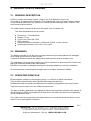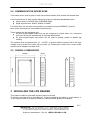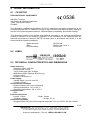
1
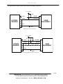
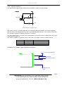
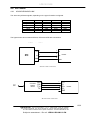
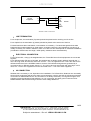
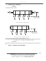
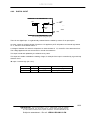
LPR 3011-RS READER USER MANUAL DOCUMENT REFERENCE: LPR3011RS-UM-1.3-EN BALOGH SA BALOGH TAG 189 Rue d’Aubervilliers - CP 97 - 75886 Paris Cedex 18 - France Téléphone: 33 (0)1 44 65 65 00 Fax: 33 (0)1 44 65 65 10 Web: http://www.balogh-rfid.com 3637 Old US-23 Brighton, Michigan MI 48114, USA Tel: USA (800) 252-RFID (7343) (810) 360-0182 Canada (800) 258-RFID (7343) Fax: (810) 360-0237 LPR 3011-RS Blank page 2/21 BALOGH SA, 189 rue d’Aubervilliers C.P. 97 75886 PARIS Cedex 18 FRANCE Tel: 33 (0)1 44 65 65 00 Fax: 33 (0)1 44 65 65 10 Internet: http://www.balogh-rfid.com PLC with a Board of Directors and a capital of 800,000 € - RCS B PARIS 582 061 073 Subject to amendment – Doc ref: LPR3011RS-UM-1.3-EN LPR 3011-RS CONTENTS 1 FOREWORD ................................................................................................. 4 1.1 1.2 1.3 1.4 2 PURPOSE OF THIS MANUAL ................................................................................... 4 DOCUMENT NAMING CONVENTIONS ..................................................................... 4 DOCUMENT STATUS SHEET ................................................................................... 4 NOTE .......................................................................................................................... 4 DESCRIPTION OF READER ....................................................................... 5 2.1 2.2 2.3 2.4 2.5 3 GENERAL DESCRIPTION ......................................................................................... 5 WARNINGS ................................................................................................................ 5 OPERATING PRINCIPLE ........................................................................................... 5 COMMUNICATION INTERFACES ............................................................................. 6 OVERALL DIMENSIONS ............................................................................................ 6 INSTALLING THE LPR READER ................................................................ 6 3.1 4 POSITIONING OF READER....................................................................................... 7 CONNEXION OF READER LPR 3011-RS .................................................. 8 4.1 4.2 4.3 4.4 5 POWER SUPPLY ..................................................................................................... 10 OPERATION OF THE INDICATOR LIGHT............................................................... 10 TTL CABLE ............................................................................................................... 10 RS CABLE ................................................................................................................ 13 READER PARAMETERS ........................................................................... 17 6 7 CHANNEL FREQUENCIES ...................................................................................... 19 MAINTENANCE .......................................................................................... 20 7.1 7.2 7.3 8 PERIODIC MAINTENANCE ...................................................................................... 20 REPLACEMENT ....................................................................................................... 20 RECYCLING ............................................................................................................. 20 LEGAL INFORMATION .............................................................................. 21 8.1 8.2 8.3 CE NOTICE .............................................................................................................. 21 LABEL ....................................................................................................................... 21 TECHNICAL CHARACTERISTICS AND DIMENSIONS ........................................... 21 3/21 BALOGH SA, 189 rue d’Aubervilliers C.P. 97 75886 PARIS Cedex 18 FRANCE Tel: 33 (0)1 44 65 65 00 Fax: 33 (0)1 44 65 65 10 Internet: http://www.balogh-rfid.com PLC with a Board of Directors and a capital of 800,000 € - RCS B PARIS 582 061 073 Subject to amendment – Doc ref: LPR3011RS-UM-1.3-EN LPR 3011-RS 1 FOREWORD 1.1 PURPOSE OF THIS MANUAL This manual presents the BALOGH HYPER X reader LPR3011-RS. It describes how to install and how to use it. Further information pertaining to the data interfaces described in this manual can be found in the Interface Manual (reference LPR3011-IM-x.y-EN). 1.2 DOCUMENT NAMING CONVENTIONS The coding used for a manual name is: <device name>- UM-II-L in which: UM signifies User Manual II refers to the issue or version number L refers to the language of the manual 1.3 DOCUMENT STATUS SHEET Version Date 1.0 1.1 1.2 1.3 11/02/2008 15/02/2008 28/03/2010 29/03/2012 Description of changes Creation Update and complement of information Correction on parameter table Update and complement of information 1.4 NOTE The contents of this manual are subject to changes without notice. BALOGH cannot be held responsible for the consequences of any error, omission, or incorrect interpretation of the information provided. 4/21 BALOGH SA, 189 rue d’Aubervilliers C.P. 97 75886 PARIS Cedex 18 FRANCE Tel: 33 (0)1 44 65 65 00 Fax: 33 (0)1 44 65 65 10 Internet: http://www.balogh-rfid.com PLC with a Board of Directors and a capital of 800,000 € - RCS B PARIS 582 061 073 Subject to amendment – Doc ref: LPR3011RS-UM-1.3-EN LPR 3011-RS 2 DESCRIPTION OF READER 2.1 GENERAL DESCRIPTION LPR3011 readers will identify HyperX™ tags on the fly at distances of up to 2m. The reader is a compact all-in-one device. The weatherproof housing of sober design contains all the functional elements of the reading unit: Antennas, Microwave generator, receiver, CPU and communication interface. The reader can be mounted directly onto any panel, even a metallic one. The main characteristics are as follows: Dimensions : 174x108x29mm Weight: 0.7 Kg Cover Color: Grey RAL 7035 IP65 protection Power requirements: between +12Vdc and +24Vdc, current 1A max. Operating temperature: from -20C° up to +50C° 2.2 WARNINGS The badges intended to use with the long range readers may be deprogrammed or damaged when using mobile phones in direct vicinity. A clearance distance between the badges and mobile phones must be at least 10 cm. The installation of the long range reader may only be carried out in places that fulfil climatic and technical conditions stated by the manufacturer. BALOGH is not liable for damages resulting from improper handling or incorrect installation. All reconstructions or technological changes result in complete exclusion of liability. 2.3 OPERATING PRINCIPLE Electromagnetic radiation in the frequency range 1 to 100 GHz is called microwaves. Their physical characteristics allow high data rates and good directivity. Reading antennas are smaller and performance is relatively independent of the environment. Tags are not active when not in the reader's antenna zone. The tag's originality (patented) is its capacity to reflect the microwaves emitted by the readers. A tag receiving an incident unmodulated 2.45 GHz carrier, will reflect this wave but modulated by its own identification code. The reader receives and processes this signal and then converts and sends the data to a host system over a standardized connection. 5/21 BALOGH SA, 189 rue d’Aubervilliers C.P. 97 75886 PARIS Cedex 18 FRANCE Tel: 33 (0)1 44 65 65 00 Fax: 33 (0)1 44 65 65 10 Internet: http://www.balogh-rfid.com PLC with a Board of Directors and a capital of 800,000 € - RCS B PARIS 582 061 073 Subject to amendment – Doc ref: LPR3011RS-UM-1.3-EN LPR 3011-RS 2.4 COMMUNICATION INTERFACES This reader can be used in place of most conventional models, both contact and contact-less. Communication with a "host" system takes place using the following standardized links: Open-collector: DATA/CLOCK, WIEGAND 26bits Serial asynchronous: RS232, RS422 or RS485 For the RS links, full two-way communication is possible using the MODBUS™ protocol. Note: all the interfaces are not available simultaneously. These readers are also equipped with: An opto-coupled digital output that can be configured to switch either via a command sent from the host or automatically at each tag identification. An opto-coupled digital input which can be used to globally enable or disable tag reading. The readers must be powered with 12 - 24 VDC. A special detector ensures that if the input voltage is too low then the reader will not power up. Powering the reader from a mains outlet requires an AC adaptor of at least 10W. 2.5 OVERALL DIMENSIONS 3 INSTALLING THE LPR READER This reader includes a removable mounting plate on its back. This plate is provided with 4x slots Ø6mm x 10mm for attaching the reader on a flat surface, or on any support made on request (screwed on a drilled metallic profiles for example). 6/21 BALOGH SA, 189 rue d’Aubervilliers C.P. 97 75886 PARIS Cedex 18 FRANCE Tel: 33 (0)1 44 65 65 00 Fax: 33 (0)1 44 65 65 10 Internet: http://www.balogh-rfid.com PLC with a Board of Directors and a capital of 800,000 € - RCS B PARIS 582 061 073 Subject to amendment – Doc ref: LPR3011RS-UM-1.3-EN LPR 3011-RS 3.1 POSITIONING OF READER The directivity of the reader's antenna is a symmetrical 90° x 90°. Mounting the reader horizontally or vertically does not affect its performance. z y 90° y 90° z Side view Top view Position the reader so that it points to the zone where the tags are likely to be. Maximum performance is always achieved with the line of sight perpendicular to the face of the reader. With a bracket the reader can be pivoted. The orientation can be freely adjusted. Pivoting can be either horizontal (side to side) or vertical (up and down). When positioning the reader, the following recommendations should be followed: Avoid placing the reader in direct sunlight, where overheating may cause the internal electronics to reach temperatures above those recommended for normal operation. If this is not possible then a sun-shield should be mounted. When two or more readers are situated in the same zone, make sure they are not pointing towards each other. If necessary, their pointing axes should be slightly redirected. The frequency channels should be as far apart as possible. A separation of 0.750 MHz is recommended for readers situated close together (see the frequency table at the end of the manual). Do not install a reader close to a source of potential interference in order not to degrade its performance. The indicated reading distance is a nominal value and the actual range is usually greater. However there are several sources of interference present in the environment which may affect reader performance and which must be taken into account. Quite often this interference cannot be removed and results in a reduced reading range. The main sources of interference are: - Devices operating in the same band of frequencies, such as communications (WLAN), - Mobile phones and smartphones, - Microwave ovens, - Fluorescent lighting, - Metal objects such as gratings, fences or heat-reflective vehicle windscreens, Etc. wireless 7/21 BALOGH SA, 189 rue d’Aubervilliers C.P. 97 75886 PARIS Cedex 18 FRANCE Tel: 33 (0)1 44 65 65 00 Fax: 33 (0)1 44 65 65 10 Internet: http://www.balogh-rfid.com PLC with a Board of Directors and a capital of 800,000 € - RCS B PARIS 582 061 073 Subject to amendment – Doc ref: LPR3011RS-UM-1.3-EN LPR 3011-RS 4 CONNEXION OF READER LPR 3011-RS HYPER.X™ reader LPR 3011-RS series are mono block readers inside a waterproof casing adapted for outdoor installation. They come in the form of a rectangular casing with light indicator at the front and 2 cables at the the bottom. TTL cable RS cable 8/21 BALOGH SA, 189 rue d’Aubervilliers C.P. 97 75886 PARIS Cedex 18 FRANCE Tel: 33 (0)1 44 65 65 00 Fax: 33 (0)1 44 65 65 10 Internet: http://www.balogh-rfid.com PLC with a Board of Directors and a capital of 800,000 € - RCS B PARIS 582 061 073 Subject to amendment – Doc ref: LPR3011RS-UM-1.3-EN LPR 3011-RS RS cable TTL cable Colour TTL cable RS cable RS-232 RS-422 RS-485 Red Vpower – reader’s ―+‖ power supply Not connected Blue GND – reader’s ―-― power supply White STROBE (ISO2) / Data 1 (WIEGAND) Brown MDATA (ISO2) / Data 0 (WIEGAND) GND E1 GND – reference for digital input TX TX+ +V Green PRES_BADGE (ISO2) Pink VI – Supply for digital output Yellow SIC – Output collector - RX+ - Grey SIE – Output emitter Rx RX- - Braided Braided - GND - TX- -V El – digital input Braided - GND 9/21 BALOGH SA, 189 rue d’Aubervilliers C.P. 97 75886 PARIS Cedex 18 FRANCE Tel: 33 (0)1 44 65 65 00 Fax: 33 (0)1 44 65 65 10 Internet: http://www.balogh-rfid.com PLC with a Board of Directors and a capital of 800,000 € - RCS B PARIS 582 061 073 Subject to amendment – Doc ref: LPR3011RS-UM-1.3-EN LPR 3011-RS 4.1 POWER SUPPLY The reader can be powered with 12Vdc to 24Vdc. The power consumption is 5W typical, 12W maximum. 4.2 OPERATION OF THE INDICATOR LIGHT The indicator light on the reader conveys the reader's behaviour to the user. It is the only visible part of the system. It is controlled by the embedded reader software. It can also be put under host control using appropriate MODBUS commands via a serial link. During the initialization phase, the light is a fixed red. If the initialization is successful, the indicator light starts to flash green, otherwise it flashes red very slowly. If after power-on the light flashes quickly, this is usually caused by a power supply problem, either voltage or current insufficient. This is not a fault condition, but an indication that a betterdimensioned power supply must be used.. During the reading of a tag, the indicator light goes out for one second, then resumes green flashing. When reading a tag with a low battery, the indicator light flashes red briefly before going out for one second, then it resumes green flashing. 4.3 TTL CABLE 4.3.1 POWER SUPPLY Colour red blue braided Name Vpower GND GND description Reader’s + power supply Reader’s – power supply Ground The power supply to the reader must be between +12VDC and +24VDC with a maximum power of 5W. 4.3.2 OPEN-COLLECTOR CONNECTION The wires convey different signals, depending on the type of interface selected. Colour white brown green blue ISO2 STROBE MDATA PRES_BADGE GND WIEGAND DATA ―1‖ DATA ―0‖ — GND 10/21 BALOGH SA, 189 rue d’Aubervilliers C.P. 97 75886 PARIS Cedex 18 FRANCE Tel: 33 (0)1 44 65 65 00 Fax: 33 (0)1 44 65 65 10 Internet: http://www.balogh-rfid.com PLC with a Board of Directors and a capital of 800,000 € - RCS B PARIS 582 061 073 Subject to amendment – Doc ref: LPR3011RS-UM-1.3-EN LPR 3011-RS The figures below show external ISO2 and WIEGAND connections 5 - 12 VDC 1K white O1 DATA1 brown O2 DATA0 HYPERX READER USER EQUIPMENT blue O5 0V GND WIEGAND reader connection 5 - 12 VDC 1K white O1 HYPERX READER CLOCK brown O2 DATA Green O3 PRES_BADGE USER EQUIPMENT blue O5 0V GND ISO2 (DATA/CLOCK) reader connection 11/21 BALOGH SA, 189 rue d’Aubervilliers C.P. 97 75886 PARIS Cedex 18 FRANCE Tel: 33 (0)1 44 65 65 00 Fax: 33 (0)1 44 65 65 10 Internet: http://www.balogh-rfid.com PLC with a Board of Directors and a capital of 800,000 € - RCS B PARIS 582 061 073 Subject to amendment – Doc ref: LPR3011RS-UM-1.3-EN LPR 3011-RS 4.3.3 DIGITAL OUTPUT The digital output is galvanically isolated from the reader by means of an optocoupler. yellow led LMB VI1 (VI2) optocoupler SIC1 (SIC2) CTP Connector JR3 SIE1 (SIE2) Circuit diagram of digital output The writing of a logic "0" and the application of an external voltage (of between 5V and 24V) applied to terminal VI turns the transistor ON. The load is connected between SIC and VI. The collector current that can circulate will produce a voltage of around 1V on this pin. If on the contrary a logic "1" is written, then the transistor is turned OFF and the voltage at the SIC pin will be the same as that on VI. The output is capable of controlling a 12V or 24V relay. It can supply a current of around 100mA. Colour pink yellow grey nom VI SIC SIE description Output supply Output collector Output transmitter EXAMPLE OF CONNECTING A BUZZER OR RELAY: VCC = 12V or 24V pink wire LPR 3011LMB VI1 (VI2) Relay SIC1 (SIC2) or buzzer with integrated oscillator Connector JR3 SIE1 (SIE2) GND blue wire bleu 12/21 BALOGH SA, 189 rue d’Aubervilliers C.P. 97 75886 PARIS Cedex 18 FRANCE Tel: 33 (0)1 44 65 65 00 Fax: 33 (0)1 44 65 65 10 Internet: http://www.balogh-rfid.com PLC with a Board of Directors and a capital of 800,000 € - RCS B PARIS 582 061 073 Subject to amendment – Doc ref: LPR3011RS-UM-1.3-EN LPR 3011-RS 4.4 RS CABLE 4.4.1 ASYNCHRONOUS LINK The wires carry different signals, depending on the type of interface configured. Colour Brown green yellow grey blue braid Pin 1 2 3 4 5 - RS-232 TX — — RX GND GND RS-422 TX+ TXRX+ RXGND GND RS-485 +V -V — — GND GND The figures below show external RS-232, RS-422 and RS-485 connections. COM port subD 9 RX PC TX GND ConnectorJR1 2 1 TX 4 3 Reader RX 5 5 GND RS-232 reader connection PC Converter RS232/ RS422 1 2 3 4 5 RX+ RXTX+ TX- TX+ TXRX+ RXGND Reader RS-422 reader connection 13/21 BALOGH SA, 189 rue d’Aubervilliers C.P. 97 75886 PARIS Cedex 18 FRANCE Tel: 33 (0)1 44 65 65 00 Fax: 33 (0)1 44 65 65 10 Internet: http://www.balogh-rfid.com PLC with a Board of Directors and a capital of 800,000 € - RCS B PARIS 582 061 073 Subject to amendment – Doc ref: LPR3011RS-UM-1.3-EN LPR 3011-RS RS-485 Equipment 1 2 3 4 5 + - TX+ TXRX+ RXGND Reader RS-485 reader connection LINE TERMINATION For a simplex link, the termination (if present) should be placed at the receiving end of the line. For a duplex link, the termination (if present) should be placed at the each end of the line. For baud rates less than 1200 bauds, no termination is necessary. For baud rates greater than 9600 bauds and line lengths greater than 1000 metres, a resistor equal to the line impedance (120 ohms) is usually necessary. For cases in-between, there is no clear-cut rule and depends on individual installations (combination of baud-rate, line-length, cable quality, emitter/receiver characteristics). ELECTRICAL CONNECTION For an RS-232 link , wiring up is straightforward, the TX and RX lines of both equipments are connected together. For a differential link (RS-422 or RS-485), the polarities are not always clearly defined. Normally the ―+‖ line is at a high level at rest and is active low. For the ―-‖ line, the opposite is true. This is the case for the differential interface for the HYPERX readers. However if the differential signals are generated by a converter acting on RS-232 signals, then the ―+‖ line can be at a low level at rest and active high. In this case, the ―+‖ line of one equipment must be connected to the ―-‖ line of the other equipment. 0V CONNECTION Whether this is necessary or not, depends on the installation. For RS-232 links, distances are necessarily short so both equipments will have the same ground potential, in which case the 0V references should be connected. For differential links, the 0V connection is not always necessary. For large link lengths, local equipment ground potentials maybe different, so a 0V connection will cause ground currents to flow. Differential links also tolerates a large common-mode voltage difference. . 14/21 BALOGH SA, 189 rue d’Aubervilliers C.P. 97 75886 PARIS Cedex 18 FRANCE Tel: 33 (0)1 44 65 65 00 Fax: 33 (0)1 44 65 65 10 Internet: http://www.balogh-rfid.com PLC with a Board of Directors and a capital of 800,000 € - RCS B PARIS 582 061 073 Subject to amendment – Doc ref: LPR3011RS-UM-1.3-EN LPR 3011-RS CONNECTION TO A NETWORK o Topology The preferred topology is the bus. R L R : line-matching resistor, added if needed Networking of readers –simplex connection R R L R : line-matching resistors, added if needed Networking of readers – half-duplex connection The length of the derivation should be as short as possible (< 30 cm). The maximum length allowed can be calculated from the cable characteristics using the equation below. L < 1300 / (Z0 x CL) L in metres, ZO in ohms and CL in pF/m o Line biasing For RS-485, line biasing may prove necessary and must be done externally and only at one point on the line. The line ―+‖ is connected to +5V via a 4K7 resistor. The line ―-‖ is connected to 0V via a 4K7 resistor. 15/21 BALOGH SA, 189 rue d’Aubervilliers C.P. 97 75886 PARIS Cedex 18 FRANCE Tel: 33 (0)1 44 65 65 00 Fax: 33 (0)1 44 65 65 10 Internet: http://www.balogh-rfid.com PLC with a Board of Directors and a capital of 800,000 € - RCS B PARIS 582 061 073 Subject to amendment – Doc ref: LPR3011RS-UM-1.3-EN LPR 3011-RS 4.4.2 DIGITAL INPUT LMB opto yellow/ jaune pink se EI1 (EI2) Zener 12V Connector JR4 white blanc GND1 (GND2) Circuit Diagram of digital input There is one digital input. It is galvanically isolated from the reader by means of an optocoupler. An open contact or positive voltage of less than 5 V applied to pin EI will produce an internal logic status of ―1‖, the bit E1 of the status word is 1. A voltage of between 5V and 24V will produce an internal status of "0", the bit E1 of the status word is 0. The voltage applied must not exceed 24V in normal circumstances. This input is read and updated by the software every 10ms. This input can enable or disable the reading of tags, for example if the input is controlled by a ground loop detector circuit. Input 1 is active-high (Vin > 5V). colour pink white pin 1 2 name EI GND description Input signal Input reference 16/21 BALOGH SA, 189 rue d’Aubervilliers C.P. 97 75886 PARIS Cedex 18 FRANCE Tel: 33 (0)1 44 65 65 00 Fax: 33 (0)1 44 65 65 10 Internet: http://www.balogh-rfid.com PLC with a Board of Directors and a capital of 800,000 € - RCS B PARIS 582 061 073 Subject to amendment – Doc ref: LPR3011RS-UM-1.3-EN LPR 3011-RS 5 READER PARAMETERS All of the parameters in the table are saved in the non-volatile memory. The number in the second column gives the order in which they are memorised. The parameters can be modified by the user using RS link and appropriate MODBUS commands. Parameter Function value Internal value Default 0 reserved 1 Channel n° 2 0 to 31 0 to 31 Persistence 3 0.1s 0 0.5s 1 1s 2 2s 3 reserved 4 Issuer code 5 5s 4 10s 5 no filtering 0 Notes x x filtering on 1st code 1 from EEPROM 2 Issuer code size 6 3 3 4 4 indicator light 7 NORMAL 0 TEST 1 message mode 8 0 0 1 1 2 2 3 3 OFF 0 ON 1 RS232 0 RS422 1 RS485 2 function tags 9 reserved 10 RS type interface 11 CO type interface 12 not used 0 ISO2 fixed 1 ISO2 var 2 WIEGAND 3 WIEGAND with 4 up to 2 codes in EEPROM 3 x 0 reserved x Not implemented x x preamble MODBUS 13 1 to 31 1 to 31 1 14 9600 0 x 4800 1 1200 2 19200 3 address Data rate 17/21 BALOGH SA, 189 rue d’Aubervilliers C.P. 97 75886 PARIS Cedex 18 FRANCE Tel: 33 (0)1 44 65 65 00 Fax: 33 (0)1 44 65 65 10 Internet: http://www.balogh-rfid.com PLC with a Board of Directors and a capital of 800,000 € - RCS B PARIS 582 061 073 Subject to amendment – Doc ref: LPR3011RS-UM-1.3-EN LPR 3011-RS Parameter Character format Frame type 15 Function value Internal value Default 8 bit no parity 0 x 7 bit even parity 1 7 bit odd parity 2 16 Polling/Interr ASCII 0 code only 1 ASCII without header reserved 2 (format TIME DESIGNA) MODBUS 3 Interrupt 0 Polling 1 0.1s 0 0.2s 1 0.5s 2 1s 3 2s 4 17 MTBM 18 x x 19 1 to 4 1 to 4 Digital Output 20 not used 0 Copy buzzer 1 reading 2s 2 host 3 Copy green led 4 tag battery low 6 copy red led 7 0 to 3 0 to 3 3 inactive 0 x active 1 100 ms 150 200 300 400 500 800 1000 OFF 0 1 2 3 4 5 6 7 0 ON 1 21 Range 22 reserved 23 Digital Intput 24 reserved reserved Hopping time 25 26 27 Serial Interface Test 28 format "test" (with header) x No. Emissions reserved Notes 1 no. of transmissions in interrupt mode x Tag reading validation x x Configuration parameters Refer to interface manual for complete description (reference LPR3011-IM-x.y-EN) 18/21 BALOGH SA, 189 rue d’Aubervilliers C.P. 97 75886 PARIS Cedex 18 FRANCE Tel: 33 (0)1 44 65 65 00 Fax: 33 (0)1 44 65 65 10 Internet: http://www.balogh-rfid.com PLC with a Board of Directors and a capital of 800,000 € - RCS B PARIS 582 061 073 Subject to amendment – Doc ref: LPR3011RS-UM-1.3-EN LPR 3011-RS 6 CHANNEL FREQUENCIES Sorted by frequency Frequency (MHz) Channel number 2446.25 31 2446.50 24 2446.75 25 2447.00 26 2447.25 27 2447.50 28 2447.75 29 2448.00 1 2448.25 2 2448.50 3 2448.75 4 2449.00 5 2449.25 6 2449.50 7 2449.75. 8 2450.00 9 2450.25 10 2450.50 11 2450.75 12 2451.00 13 2451.25 14 2451.50 15 2451.75 16 2452.00 17 2452.25 18 2452.50 19 2452.75 20 2453.00 21 2453.25 22 2453.50 23 2453.75 30 Sorted by channel number Channel number Frequency (MHz) 1 2448.00 2 2448.25 3 2448.50 4 2448.75 5 2449.00 6 2449.25 7 2449.50 8 2449.75. 9 2450.00 10 2450.25 11 2450.50 12 2450.75 13 2451.00 14 2451.25 15 2451.50 16 2451.75 17 2452.00 18 2452.25 19 2452.50 20 2452.75 21 2453.00 22 2453.25 23 2453.50 24 2446.50 25 2446.75 26 2447.00 27 2447.25 28 2447.50 29 2447.75 30 2453.75 31 2446.25 Channel number 0 is used for the frequency hopping mode. In this mode, the reader operates for a certain time on one channel, then hops onto another channel, and so on. The sequence is pseudo-random and the time the reader spends on any particular channel is determined by the "Hopping period" parameter. The frequencies/channels used cover all of the available frequency band. 19/21 BALOGH SA, 189 rue d’Aubervilliers C.P. 97 75886 PARIS Cedex 18 FRANCE Tel: 33 (0)1 44 65 65 00 Fax: 33 (0)1 44 65 65 10 Internet: http://www.balogh-rfid.com PLC with a Board of Directors and a capital of 800,000 € - RCS B PARIS 582 061 073 Subject to amendment – Doc ref: LPR3011RS-UM-1.3-EN LPR 3011-RS 7 MAINTENANCE 7.1 PERIODIC MAINTENANCE The LPR 3011-RS reader requires no periodic maintenance The reader should be regularly cleaned in order to avoid dust and dirt accumulating on the case. The reader should be regularly checked for: cracks in the case Fixing screws correctly tightened cables correctly connected with no injuries 7.2 REPLACEMENT If the LPR 3011-RS needs to be replaced, the procedure is as follows: Turn off power supply, and disconnect all cables Record the reader orientation (azimuth and elevation), then remove the mounting screws and dismount the unit. Place the new unit in the same position, insert the mounting screws and tighten correctly. Reconnect all cables and power up the reader. . 7.3 RECYCLING All decommissioned readers must be returned to BALOGH SA for appropriate recycling according to directive D3E. 20/21 BALOGH SA, 189 rue d’Aubervilliers C.P. 97 75886 PARIS Cedex 18 FRANCE Tel: 33 (0)1 44 65 65 00 Fax: 33 (0)1 44 65 65 10 Internet: http://www.balogh-rfid.com PLC with a Board of Directors and a capital of 800,000 € - RCS B PARIS 582 061 073 Subject to amendment – Doc ref: LPR3011RS-UM-1.3-EN LPR 3011-RS 8 LEGAL INFORMATION 8.1 CE NOTICE DECLARATION OF CONFORMITY BALOGH Toulouse 105 Avenue du Général Eisenhower 31023 TOULOUSE cedex 1 FRANCE 0536 This declaration certifies that the device LPR 3011 satisfies the essential requirements of the European directive R&TTE 1999/5/EC aiming to align the laws of the Member States relating to the use of the electromagnetic spectrum, electromagnetic compatibility and electrical safety. This declaration applies to all readers manufactured according to the technical specifications outlined in Annexe II of the directive. Evaluation of the conformity of the equipment with the essential requirements of article 3 R&TTE has been done in accordance with Annex IV of the directive and the following standards: Radio spectrum: EMC: Electrical safety: EN 300 440 EN 301 489-1 and -3 EN 60 950 8.2 LABEL 8.3 TECHNICAL CHARACTERISTICS AND DIMENSIONS Radio frequency • Frequency band: 2.45 GHz • Emitted power: 10mW • Tag to reader data rate: 30 Kbps • Modulation: BPSK (Biphase Shift Keying) • Protocol: HDLC • Number of channels: 31 Power supply • Voltage range: 12 to 24 Volts DC • Current: 1A max Environmental conditions • Relative humidity: 90% non-condensing • Storage temperature: -25° to +80° C • Operating temperature: -20° to +50° C Protection class • IP65 External dimensions • Length: 174mm • Width: 108mm • Thickness: 29mm • Weight: 0.7 kg Connections available • Wiegand 26bits, DATA/CLOCK (magnetic stripe ISO 7811-2), RS 232, RS 422, RS485 21/21 BALOGH SA, 189 rue d’Aubervilliers C.P. 97 75886 PARIS Cedex 18 FRANCE Tel: 33 (0)1 44 65 65 00 Fax: 33 (0)1 44 65 65 10 Internet: http://www.balogh-rfid.com PLC with a Board of Directors and a capital of 800,000 € - RCS B PARIS 582 061 073 Subject to amendment – Doc ref: LPR3011RS-UM-1.3-EN