1
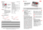
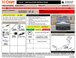
TABLE OF CONTENTS
Preface -----------------------------------------------------------------------------------------------------------------Safety Notes ----------------------------------------------------------------------------------------------------------Overview ---------------------------------------------------------------------------------------------------------------Some component assembly required -----------------------------------------------------------------------Components of the product ------------------------------------------------------------------------------------Graphic panel velcro attachment -----------------------------------------------------------------------------Graphic holder use ------------------------------------------------------------------------------------------------Change arm assembly -------------------------------------------------------------------------------------------Opening the sign ---------------------------------------------------------------------------------------------------Attaching graphic panels to holders -------------------------------------------------------------------------Copy/Graphic changing------------------------------------------------------------------------------------------Cleaning and Maintenance -------------------------------------------------------------------------------------Re-painting/touch-up -----------------------------------------------------------------------------------------------
2
3
4
4
4
5-6
7
8-9
9
9
10-11
12
12
Overview of Graphic Reader Board kit:
This document is to familiarize you with the graphic reader
board components, assembly and usage. If you have never
used this product please read and understand this manual
before continuing. This document is to be used for both
the 2’ x 8’ and 3’ x 8’ Graphic reader board signs.
Graphic reader
board with
graphic panels
installed
Description and purpose of the graphics reader board:
This reader board is unique in the it gives you an opportunity
to market and display your products with either graphic
panels or copy letters. Internal illumination allows continuous
communication to potential passing customers passing by
day or night, and they will be able to see either option from a
distance which will stimulate them visually. With the interchangeable copy and graphic panels the options are endless.
WARNING:
Do not attempt to change the graphics in the reader board if the wind speed is 10 mph or above.
This may damage the graphic or cause bodily injury to the operator from a free falling graphic.
Only the operator should be allowed to stand underneath the reader board during the
hanging/changing process.
Graphic Reader Board User Manual
Page 1
Preface:
Introduction:
This document contains all information necessary show you how to set up, change graphics and
maintain your reader board. Each area will be explained and visualized for your convenience.
Topics to be covered:
Overview:
This section explains the purpose and parts of the reader board.
Graphic Panel velcro attachment:
This section covers the procedure for aligning and attaching self-adhesive velcro pieces that will
allow the graphic panels of the reader board to be attached to the graphic hangar bars.
Copy/Graphic changing:
This section covers the graphic and copy changing procedures, and provides pictures and
illustrations to help you in this area.
Cleaning and Maintenance:
This section covers processes and methods to keep your reader board clean without damaging
paint or plastic faces, graphics or letters.
Re-painting/touch-up:
This section covers guidelines for any re-painting or touch-up necessary to maintain the
appearance of your reader board.
Graphic Reader Board User Manual
Page 2
Safety Notes:
Look for these symbols in the users manual to maximize safety and protection.
Follow all warning instructions to maintain safe operation of your signs.
Hazardous voltage warning:
DANGER
Voltage Hazard
This sign uses hazardous voltages that may cause serious injury
or death. Do not modify the safety features of the sign in any
way to acquire access to this hazardous voltage.
Lifting warning:
WARNING
Lifting hazard
Single person lift
could cause injury.
Use assistance when
moving or lifting.
Wind speed warning:
WARNING:
Do not attempt to change the graphics in the reader board if the wind speed is 10 mph or above.
This may damage the graphic or cause bodily injury to the operator from a free falling graphic.
Only the operator should be allowed to stand underneath the reader board during the
hanging/changing process.
Graphic Reader Board User Manual
Page 3
Overview of Graphic Reader board kit:
This document is to familiarize you with the graphic reader board components, assembly and
usage. If you have never used this product please read and understand this manual before
continuing.
Some assembly is required for the graphics reader board components:
This reader board is unique in the it gives you an opportunity to market and display your products
with either graphic panels or copy letters. Some assembly is required at the location which
includes the change arm being attached to the graphic changer head, and velcro pieces being
attached to the individual graphic panels before they can be installed in the reader board sign.
2
GRAPHICS READER BOARD PARTS:
3
1) Changer head:
Attachment for the change arm to change graphic
panels. Will need to be attached to change arm when
received for use.
1
2) Suction cup:
Attachment for the change arm to change letter panels.
This comes in the change arm package and will be
used when putting copy change letters on the reader
board instead of graphics panels.
4
3) Change arm:
Device expandable from 6’ to 18’ to change reader
board graphics or letters and open cabinet.
4) Cabinet opening attachment:
Attachment for the change arm to open the graphics
reader board for service, graphics or copy changes.
5
5
5) 1 ½” Velcro pieces:
Velcro pieces to be attached to the graphics panel in
the field.
Graphic Reader Board User Manual
Page 4
6) Graphics hangar bar:
These (8) parts (4 per frame) come with pieces of
velcro that will be the points where the graphic panels
attach to the hangar bars.
6
7) Graphics holder:
Aluminum pieces designed to keep your reader board
graphics in order for carrying and installation.
8) #12 x 1 ½” Self-tapping screws:
These screws will be inserted into the pole supporting
the sign to hang the graphics holders on when changing
the graphics
8
7
Graphic Panel velcro attachment:
Use the following instructions to apply the self-adhesive velcro to the graphic panels for your
graphic reader board.
When your receive your graphics panels they must be modified by attaching pre-cut selfadhesive velcro pieces in designated spots that will allow them to be attached to the graphic
hangar bars that are included in the graphics reader board kit. Care must be taken during
this procedure to clean both hands and panels so that there is no oil or residue of any kind,
this will interfere with the bond between the velcro and the panels and decrease the life
of the bond.
**IMPORTANT NOTE**
For best results and longevity apply the velcro pieces at room temperature
and allow to cure/bond for 24 hours before installing on the graphic holder.
This will improve the bond between the panels and the velcro.
Graphic Reader Board User Manual
Page 5
Velcro attachment steps:
1) Open the graphics panels and remove one. Find a clean,
flat surface and with the panel white side up make sure
the panel surfaces in the areas marked by the yellow
boxes in photo #1 are clean using alcohol.
1
** NOTE: VERY IMPORTANT **
PANELS AND HANDS MUST BE CLEAN AND FREE OF ANY OIL
OR RESIDUE OF ANY KIND. FAILURE TO DO THIS WILL RESULT
IN THE VELCRO NOT ADHERING TO THE PANELS CORRECTLY.
2) Use a #2 pencil to mark the top left corner of the
panel as shown. The top gap is 1/8” and the side
gap is 1/4”. The marked area shows the upper
corner of where the velcro will be placed.
2
3) Take the paper backing off a velcro piece and
attach it as shown in (photo #3). Apply pressure
evenly starting at one end of the velcro and
working to the other end to improve the bond
of the velcro and panel.
4) Repeat steps 2 & 3 on the right corner of the
panel as shown in (photos #4 & #5).
3
5) Repeat the marking procedure on the rest of
the panels until all 8 are done. (4 panels per sign).
4
5
Graphic Reader Board User Manual
Page 6
Attachment of graphic panels to graphics holders
1
1) Each graphics reader board comes with (2) graphics
holders to store and carry the graphic panels. (Photo #1)
shows how the holders are shipped back to back attached
by velcro in (photo #2). (Photo #3) shows the velcro for
attaching the graphic panels and the horizontal alignment
lines to keep the panels even as you put them on the holder.
The holders have a hole in the upper part and can be hung
on a wall to store them as in (photo #4).
2
3
4
Reminder: Wait until after the 24 hour waiting period to put panels on the graphics holders.
NOTE: The graphics in the pictures are not in the correct order, the pictures are just for reference.
2) On the front/top of the graphic panels you will notice the graphics are marked A,B,C & D. This
is the order that they must be hung in the sign from left to right. To stage them on the graphics
holder you must start with the “D” panel as it will be installed last (photo # 5). Line up the left
end of the panel, and using the alignment lines press the panel into place on the graphic holder.
3) Continue to attach the panels upward on the graphics holder in the D,C,B,A order. When you
have them all attached you will have another set to attach for the second reader board. Attach
them in the same way until you have (8) graphics panels on the graphics holder. (photo #6)
5
6
Graphic Reader Board User Manual
Page 7
Initial Copy/Graphic changing:
Use the pictures and illustrations to change the graphic and copy in your graphics reader board.
The panels are marked A,B,C & D and must be put up in that order.
1) Take the graphic holders and put them back to back as
they were when they were shipped. Carry the graphic
holders, graphic hangar bars and graphic change arm
out to the graphics reader board and hang the graphic
holder one of the screws mounted directly under the
sign on each side of the support pole.
NOTE: The illustration on the right shows the empty graphic
holder which would be hung opposite the graphic holder
full of graphic panels. For the initial graphic
installation the empty graphic holder would not be used.
Graphic
reader
board
Support
pole
#12 x 1 ½”
screw
(each side
of pole)
Full
Graphic
Holder
NOTE: The graphic changer head must be attached to the
change arm and the length of the change arm must be adjusted
so you can reach approximately to the top of the sign before
opening or changing graphics on your graphics reader board.
Side 1
2) Take the 1” bolt out of the rachet base and leave on (1)
star washer. With the bend in the changer head toward
the change arm as shown in (photo #1), put the bolt
through the hole in the changer head, put the other star
washer on the bolt and thread it into the changer rachet
(photo #1)
Empty
Graphic
Holder
Side 2
4
5
2
1
3
6
3) Align and tighten the changer head as shown in (photo
#2). Use a ½” wrench for this taking care not to strip
threads on the blue plastic changer head.
2
1
8
2
1
7
1
2
3
4
5
6
7
8
Graphic Reader Board User Manual
5/16” X 1” BOLT
5/16” STAR WASHER
CHANGER ‘RACHET’ PIECE
‘RACHET’ BASE
1/4” EYEBOLT
CHANGE ARM
CHANGE ARM COLLAR
ALUMINUM GRAPHIC CHANGER
Page 8
4) Note the correct position to open and close the sign face, standing in the wrong position may
cause problems opening and closing the graphics reader board. Use the hook attachment on
the end of the change arm (photo #1). Hook the opening eye (photo #2) of the reader board
sign with the J-bolt of the change arm and pull down to open the sign. After the sign is open
the gas struts will assist in opening it the rest of the way.
1
2
x
EYEBOLT FOR
OPENING CABINET
x
You’re now ready to mount the graphic panels to the graphic arms and hang them in your
reader board. On the graphic hangar bars in (photo #3) you will notice there are (2) velcro
pieces that will be the mounting point for the graphics panels. (photo #4) shows how the velcro
pieces align on the graphic hangar bar and the graphic panels. (Photo #5) shows the mounted
graphic.
3
4
5
ALIGNMENT SLOTS IN GRAPHIC
PANELS TO HOLD GRAPHIC
PANELS IN PLACE.
6
5) Mount the “A” panel to the hangar bar by bending
back the top/ends of the panels (photo #6)
as you slide the alignment pins of the hangar bar
into the slots on top of the panel until they bottom
in the slot, then push the ends of the panel against
the hangar bar.
ALIGNMENT PINS
ALIGNMENT SLOT
Graphic Reader Board User Manual
VELCRO
Page 9
WARNING:
Do not attempt to change the graphics in the
reader board if the wind speed is 10 mph or above as this
may damage the graphic or cause bodily injury to the
operator from a free falling graphic.
1
Only the operator should be
allowed to stand underneath the reader board during the
hanging/changing process.
6) Take the change arm and slide the changer head slots
up to the alignment pins on the hangar bar. You may have
to lay the graphic panel mounted on the graphic hangar on
the ground as in (photo #1). When the changer head is in
position as in (photo #2) you can pick the graphic up.
2
7) Lift the graphic up the sign (photo #3) and place it on the
hangar bar channel at the top of the sign starting on the
left hand side. (Photo #4) shows how the graphic hangar
sits on top of the hangar bar channel.
.
8) (Photo #5) shows the slot on the back of the graphic
hangar that is to align on top of a locator pin in the hangar
bar channel for consistent graphic placement. When you
have the graphic on the channel move the graphic back
and forth slightly so it can drop onto the alignment pin.
The ’A’ panel is now in place. (Photo #6) shows the pane
properly installed on the reader board.
GRAPHIC
PANEL
4
GRAPHIC
HANGAR
CHANNEL
GRAPHIC
HANGAR
BAR
5
3
6
ALIGNMENT
SLOT
Graphic Reader Board User Manual
Page 10
9) Mount panel “B” to a graphic hangar bar and lift it up onto
the graphic bar channel and seat it the on the locator pin.
Panel ‘B’ is in place (photo #1).
1
NOTE: When properly installed each graphic panel will overlap
the panel next to it approximately 3/16” which makes the display
look seamless. If the graphics don’t overlap each other correctly
you might have to pull the edge of one graphic slightly forward
to complete the overlap. To do this slide the changer head
under the edge of one of the panels while pressing the graphic
next to it down with the other side of the changer as in (photo #)
2. This will align the panels correctly.
10) Mount panel “C” to a graphic hangar bar and lift it up onto
the graphic bar channel and seat it the on the locator pin.
Panel ‘C’ is in place (photo #2). Use the changer head to
correct overlap problems as described in the above note.
2
11) Mount panel “D” to a graphic hangar bar and lift it up onto
the graphic bar channel and seat it the on the locator pin.
Panel ‘D’ is in place (photo #3). Use the changer head to
correct overlap problems as described in the above note.
12) When you have the panels all in place the sign is ready to
be closed. Stand in the correct position and using the
J-bolt end of the change arm hook the opening eye of the
latch assembly and pull down on the sign face slowly until
it closes. If the face doesn’t completely close take the
J-bolt and push on the latch assembly to seat it. Without
pulling down turn the opening eye until it is perpendicular
to the face of the sign. It should lock into position.
3
This completes your change over operation.
5
4
4
Graphic Reader Board User Manual
Page 11
Maintenance:
A supervisor should be alerted if the graphics reader board doesn’t illuminate correctly or at
all because of faulty wiring, or burned out fluorescent bulbs. DO NOT attempt to correct any
problems yourself as there are hazardous voltages present.
DANGER
Voltage Hazard
This sign uses hazardous voltages that may cause serious injury
or death. Do not modify the safety features of the sign in any
way to acquire access to this hazardous voltage.
INSTALLER:
To access inside
of sign remove
these (3) screws
from the latch
strike plate in the
center of the cabinet
latch
strike plate
screws
Cleaning:
Care should be taken when cleaning the reader board sign. Abrasive cleaners including
some window cleaners and solvents such as gasoline, lacquer thinner, acetones, and
chlorinated solvents will damage plastic.
Plastic faces should be washed with a mild soap/detergent and warm water mixture. A
sponge cloth, or soft, clean woven fabric can be used but without using a lot of pressure.
Rinse thoroughly with clean water. Dry faces by taking a clean chamois, cloth of cellulose
tissue and blotting the water droplets. The surface may be easily scratched if rubbed.
Contamination that can’t be removed with detergent can usually be removed with kerosene,
hexane or painter’s nephtha. Use the same technique as you did with the detergent and
do not rub the surfaces, then gently blot the excess with a clean cloth or tissue. These
solvents can be obtained at a hardware or paint store, and should be used according
to the manufacturer’s directions. Any oily film left from a solvent cleaning should be
removed immediately with detergent.
Field Application or Touch-up w/Spraylat Mark I:
1) To assure that the same color is achieved consistently, make sure to stir the product well before
using. If any pigment settling is evident on the bottom of the container, (which is not unusual),
loosen it with stirring stick and continue to mix until the color is consistent.
2) To spray or brush Mark 1 for field touch up, the color base should be mixed in the following
manner: Mix three parts (by volume) of color base with one part (by volume), SM150V/SM151C
catalyst. Stir well.
3) Brushing this product is possible in the field using application tools designed for catalyzed
urethane products (China Bristle). Brush strokes should be kept to a minimum to avoid a rough
appearance and reduce overall gloss of the product. This material has a 1-2 hour pot life after
mixing. Any unused paint and all mixing and application equipment should be flushed and cleaned
within 15 minutes after mixing or use. Temperatures exceeding 90 degrees Fahrenheit will shorten
pot life.
Graphic Reader Board User Manual
Page 12