1
26
CHAPTER 3. TOOLBOX TUTORIAL
option is not specified, the current selection is appended to the existing one. For
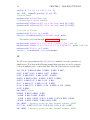
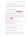
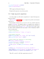
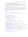
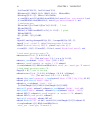
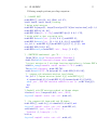
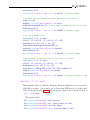
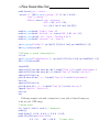
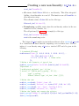
each project, you should typically edit a script similar to the following
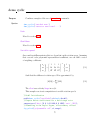
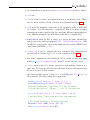
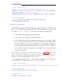
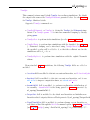
cf=demo_cyclic(’BuildStep0’);
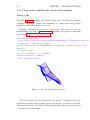
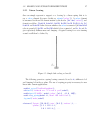
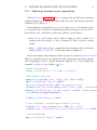
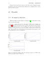
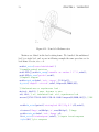
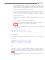
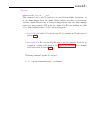
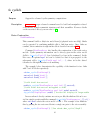
% Viewing mesh step 1: disk elements
fe_cyclicb(’DisplayAllEdges’,cf);
%fe_fmesh(’3dLineInit’,cf); % right click ’Type’ or ’Done’
L=[1 3 5 15 26 0 1121 1123 1125 1135 1146 0 13 15 18 1133 1135 1138];
fe_cyclicb(’MeshRimLine2Patch -reset’,cf,L);
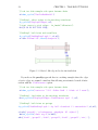
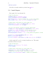
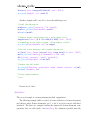
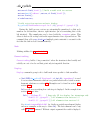
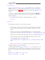
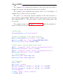
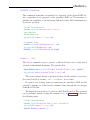
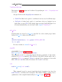
% Viewing mesh step 2: blade elements
% disk1
fe_cyclicb(’DisplayFirst’,cf,{’disk1’});
%fe_fmesh(’3dLineInitAddInfo Quad4’,cf); % pick four nodes to form a quad
% use right click ’Type’ or ’Done’ to display
Elt=[Inf abs(’quad4’);
154 156 152 148 1 1;148 146 150 154 1 1;
146 142 144 150 1 1;142 111 83 144 1 1];
fe_cyclicb(’MeshRimLine2Patch’,cf,Elt);
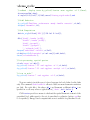
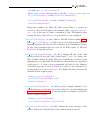
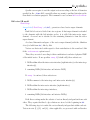
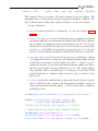
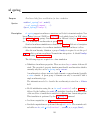
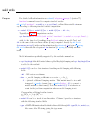
% disk2
fe_cyclicb(’DisplayFirst’,cf,{’disk2’});
fe_fmesh(’3dLineInitAddInfo Quad4’,cf); % pick four nodes to form a quad
model.Elt=[Inf abs(’quad4’);
1274 1276 1272 1270 1 1;1270 1272 1268 1266 1 1
1266 1268 1264 1262 1 1;1262 1231 1203 1264 1 1];
fe_cyclicb(’MeshRimLine2Patch’,cf,model.Elt);
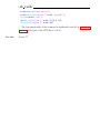
fecom(’ShowPatch’);
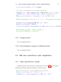
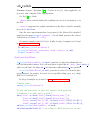
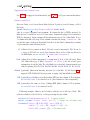
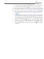
% save cf.Stack{’info’,’ViewMesh’}
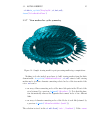
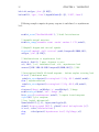
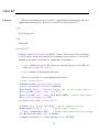
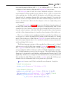
% Once the geometry generated typical calls are
fesuper(’Sebuildsel -initrot’,cf,cf.Stack{’info’,’ViewMesh’})
fe_cyclicb(’Displaysel 2’,cf,def,cf.Stack{’info’,’ViewMesh’})
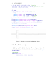
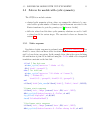
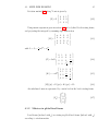
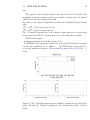
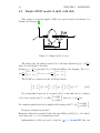
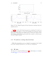
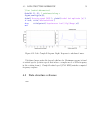
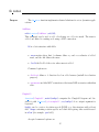
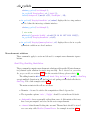
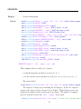
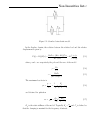
3.2
Bearing and support representations