1
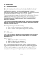
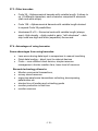
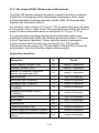
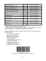
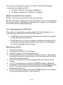
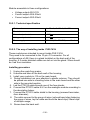
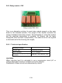
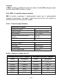
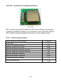
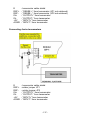
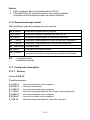
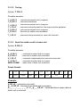
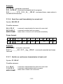
Module accessible in three configurations:
•
•
•
Voltage output AN 0-10V
Current output AN 4-20mA
Current output AN 0-20mA
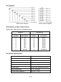
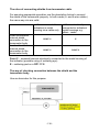
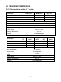
30.2.1. Technical specification
Work modes
4 - 20mA , 0 - 20mA, 0 - 10V
Resolution
16 bit
Current output resistance
<500
Voltage output resistance
>400
Power supply
24V DC (12 - 30V DC) max 40mA
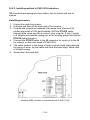
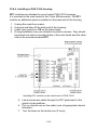
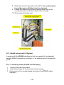
30.2.2. The way of installing inside PUE C41H
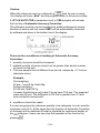
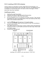
These modules are intended to mount inside PUE C41H.
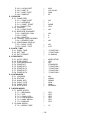
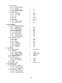
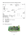
They need to be connected to the 10-pin J12 connector. For all
configurations of AN, there is a gland installed on the back wall of the
housing. A 3-meter shielded cables are led out via the gland. Wires should
be free from insulation.
Installing procedure:
1.
2.
3.
4.
5.
6.
7.
8.
9.
Unplug the scale from mains;
Unscrew and take off the back wall of the housing;
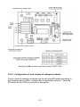
Install your module in J12 on the main board;
During installation turn your attention to plastic columns. They should
be placed one side in mounting holes in the main board and the other
side in the mounted module;
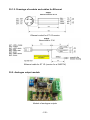
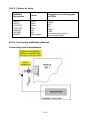
Led the PT0015 cable through one of the free glands;
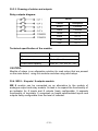
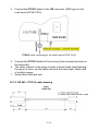
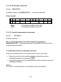
Connect the PT0015 cable to J3 on the analogue module according to
the description below;
Connect the PT0015 cable shield to the housing (screwed terminator,
4mm diameter);
The cable connect to the group of wires (unhook band clips fastening
the group of wires, lay the cable and hook the band clips). Band clips
of multiple usage;
Screw down the back wall.
- 126 -