1
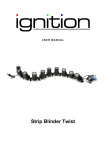
stainless steel
range hood
Model#: 654OSA008STS
Installation
Guide and
User Manual
Please read and save this guide before using your range hood.
Store the guide in a safe place so you will know where it is
when you want to refer to it.
IMPORTANT
Carefully check the unit prior to installation to ensure there is no damage.
Do not dispose of any packaging until you are satisfied with your new
range hood.
If you have any problems with this unit or there are
missing or damaged parts, please call toll free:
1-800-459-4409
DO NOT RETURN THE UNIT TO THE PLACE OF PURCHASE
before calling the toll free number above.
• Read and save these instructions. Save this guide for local electrical
inspector’s use.
• Approved for residential appliances.
• For residential use only.
Installation must comply with all local codes.
• Requirement: 120V AC, 60Hz. 15 or 20 A Branch Circuit.
• Read all instructions before proceeding.
• Turn off power circuit breaker before wiring this appliance.
Installer: Must leave instructions for this unit with owner.
Homeowner: Please retain these instructions for future reference and
for local electrical inspector’s use.
2
IMPORTANT SAFETY INSTRUCTIONS
Read all instructions before installing and operating this appliance.
Installation
Do not install if the appliance is damaged.
1.The instructions in this manual are intended for qualified installers,
service technicians or other qualified persons. NEVER attempt to
install this appliance yourself.
2.Installing the unit without an electrical and technical background could
result in injury.
3.All electrical wiring must be properly installed, insulated and grounded.
Old duct work should be cleaned or replaced if necessary to avoid
the possibility of a grease fire. Check all joints on duct work to insure
proper connection. All joints should be properly taped.
4.Personal injury hazard. Because of the weight and size of the range
hood, two or more people are needed to move and safely install the
range hood. Failure to properly lift range hood could result in damage
to the product or personal injury.
5.SEVERE INJURY - Range hood may have very sharp edges. Please
wear protective gloves to remove any parts for installing, cleaning or
servicing.
6. DO NOT INSTALL CLOSER THAN 61 CM (24 INCHES) ABOVE
COOKING SURFACE.
Operations
1.Read all instructions in this manual before operating the appliance.
2.Always leave safety grills and filters in place. Without these components,
operating blowers could catch on to hair, fingers and loose clothing.
3.NEVER dispose of cigarette ashes, ignitable substances, or any foreign
objects in blowers.
4.NEVER leave cooking unattended. Use caution when cooking with oil.
Overheating may cause oil to reach its flash point and ignite. Used oil
will ignite at lower temperatures than fresh oil.
5.NEVER cook over open flames under the range hood. Constantly
monitor deep-fryers during use, as overheated oil may ignite.
3
Cleaning
Do not operate blowers when filters are removed.
1.The saturation of greasy residue in the blower and filters may cause
increased flammability. Keep this appliance clean and free of grease
and residue build-up at all times to prevent possible fires.
2.Filters must be cleaned periodically and kept free from accumulation
of cooking residue (see cleaning instructions inside). Old and worn
filters must be replaced immediately.
3.NEVER disassemble parts to clean without proper instructions. Parts
should be disassembled by qualified persons only.
The manufacture and distributors decline all responsibility in the event of failure to
observe the instructions given here for installation, maintenance and suitable use
of the product. The manufacturer and distributors further decline all responsibility
for injury due to negligence and the warranty of the unit automatically expires due
to improper maintenance.
Workman Safety Gloves
Safety Note:
Remove PVC film before installation. Always wear “Safety Workman
Gloves” for installation, cleaning, light bulb changing and dismantling to
reduce the risk of injury.
4
BEFORE YOU START...
It is very important for your safety and the safety of others that you follow
the many important safety messages in this manual and on your appliance. Always read and obey all safety messages. All safety messages
will tell you what the potential hazard is, how to reduce the possibility of
injury, and what can happen if the instructions are not followed.
This safety alert symbol alerts you to potential hazards that can kill
or hurt you and others. All safety messages will follow the safety
alert symbol and the word “WARNING.”
READ AND SAVE THESE INSTRUCTIONS
WARNING : TO REDUCE THE RISK OF FIRE, ELECTRIC SHOCK, OR
INJURY TO PERSONS, OBSERVE THE FOLLOWING CAREFULLY:
1) Use this unit only in the manner intended by the manufacturer. If
you have any questions, contact the distributor, importer or the
manufacturer.
2) Before servicing or cleaning the unit, switch power off at the junction
box and lock the panel door to prevent power from being switched on
accidentally. If the junction box door cannot be locked, securely fasten
a prominent warning sign to the panel door.
3) Installation work and electrical wiring must be done by qualified
person(s) in accordance with all applicable codes and standards,
including fire-related construction.
4) Sufficient air is needed for proper combustion and exhausting of gases
through the flue (duct cover) of fuel burning equipment to prevent
back drafting. Follow the heating equipment manufacturer’s guidelines
and safety standards such as those published by the National Fire
Protection Association (NFPA) and the American Society for Heating,
Refrigeration and Air Conditioning Engineers (ASHRAE), and the local
code authorities.
5) When cutting or drilling into the wall or ceiling, do not damage electrical
wiring and hidden utilities.
6) Ducted fans must always be vented to the outdoors.
5
WARNING: To reduce the risk of fire, use only metal duct work.
CAUTION: For general ventilation use only. Do not use the range hood
fans to exhaust hazardous or explosive vapours.
WARNING : To reduce the risk of injury in the event of a range
top grease fire, observe the following: (Based on “kitchen fire safety
tips” published by the NFPA)
1) SMOTHER FLAMES with a close-fitting lid, cookie sheet, or metal tray,
then turn off the burner. BE CAREFUL TO PREVENT BURNS. If the
flames do not go out immediately, EVACUATE AND CALL THE FIRE
DEPARTMENT.
2) NEVER PICK UP A FLAMING PAN - you may be burned.
3) DO NOT USE WATER, including wet dishcloths or towels - a violent
steam explosion will result.
4) Use an extinguisher ONLY if:
a)You know you have a class ABC extinguisher, and you already know
how to operate it.
b)The fire is small and contained in the area where it started.
c)The fire department is being called.
d)You can fight the fire with your back to an exit.
CAUTION: To reduce risk of fire and to properly exhaust air, be sure to
vent air outside - do not vent exhaust air into spaces within walls, ceilings, attics, crawl spaces, or garages.
WARNING: To reduce the risk of fire or electric shock, do not use this
hood with any external solid state speed control device.
6
WARNING: FOR GENERAL VENTILATION USE ONLY. DO NOT
USE THIS RANGE HOOD TO VENTILATE HAZARDOUS OR
EXPLOSIVE MATERIAL AND VAPOURS.
TO REDUCE THE RISK OF A RANGE TOP GREASE FIRE:
1) Never leave range unattended when in use.
2) Boil overs cause smoking and greasy spillovers that may ignite.
3 Heat oils slowly on low or medium setting.
4) Always turn hood ON when cooking at high heat or when cooking
flaming foods (i.e. Crepes Suzette, Cherries Jubilee, Peppercorn
Beef Flambe).
5) Clean ventilation fans frequently.
6) Grease should not be allowed to accumulate on fan or filters.
7) Use proper pan size.
8) Always use cookware appropriate for the size of the surface element.
To get the best performance, the vertical clearance between the cook-top
and the range hood should range from 61 cm - 76.2 cm (24 in. to 30 in).
GROUNDING INSTRUCTIONS
This appliance must be grounded. In the event of an electrical short circuit,
grounding reduces the risk of electric shock by providing an escape wire
for the electric current.
WARNING: Improper grounding can result in a risk of electric shock.
Consult a qualified electrician if the grounding instructions are not
completely understood or if doubt exists as to whether the appliance is
properly grounded.
CAUTION: The range hood has a thermally protected system for the
motor, which will shut down automatically if the motor is overheated.
If the overheat protection trips, disconnect the power and wait for 10
minutes until the motor cools down.
7
ELECTRICAL REQUIREMENTS
OBSERVE ALL GOVERNING CODES AND ORDINANCES
IMPORTANT: It is the customer’s responsibility to contact a qualified
electrical installer and assure that the electrical installation is adequate
and complies with the National Electrical Code, or CSA standards and all
local codes and ordinances.
WARNING
* Electrical grounding is required for this range hood.
* Check with a qualified electrician if you are not sure whether the range
hood is properly grounded.
* Failure to follow electrical requirements may result in a fire.
* A fuse in the neutral or grounding circuit could result in electrical shock.
* If the hot/cold water pipe is interrupted by plastic nonmetallic gaskets or
other materials, DO NOT use for grounding.
* * DO NOT ground to a gas pipe.
1. Save installation instructions for electrical inspector’s use.
2. If codes permit and a separate ground wire is used, it is recommended
that a qualified electrician determine if the ground path is adequate.
3. DO NOT use an extension cord or adapter plug with this appliance.
4. RISK OF ELECTRICAL SHOCK - This range hood must be properly
grounded.
5. The range hood must be connected with copper wire only.
6. The range hood should be connected directly to the junction (or circuit
breaker) box through flexible, armoured or nonmetallic sheathed
copper cable. Allow some slack in the cable so the appliance can be
moved if servicing is ever necessary.
7. A UL listed or CSA approved conduit connector must be provided
at each end of the power supply cable (at the range hood and at the
junction box).
8
8. When making the electrical connection, cut a 3.2 cm (1-1/4 in.) hole
in the wall. A hole cut through wood must be sanded until smooth.
A hole through metal must have a grommet.
9. When cutting or drilling into the wall or ceiling, do not damage
electrical wiring and other hidden utilities.
10.Wire sizes must conform to the requirements of the National
Electrical Code ANSI/NFPA 70 - latest edition*, or CSA Standards
C22.1-94, Canadian Electrical Code Part 1 and C22.2 No. 0-M91 latest edition** and all local codes and ordinances.
11.Connect Black to Black, White to White and Green to Green
wires from the range hood to the house wiring and cap with wire
connectors.
Range hood wiring
BLACK ( Live )
WHITE ( Neutral )
GREEN/YELLOW ( Ground )
White (N)
Black (L)
Wiring from
electrical source
Yellow/Green (G)
WARNING
ELECTRICAL SHOCK HAZARD
Do not perform service on an electrically
live system. Disconnect the main electrical
supply before servicing this device.
Touching electrical connectors or other
exposed electrical circuitry inside this range
hood when they are energized could result
in death, serious bodily injury, or property
damage.
* National Fire Protection Association Batterymarch Park Quincy,
Massachusetts 02269
** CSA International, 178 Rexdale Boulevard, Toronto, Ontario,
CANADA, M9W 1R3
9
LIST OF MATERIALS
TOOLS FOR INSTALLATION:
utility knife
level
measuring tape
marker or
pencil
tape
powered
screwdriver
or drill
flat-blade
screwdrivers
adjustable
wrench
Philips
screwdrivers
hammer
Notice:
1.Remove the range hood from the carton packaging and place on a
flat surface for assembly.
2.Check carefully to ensure there are no missing parts or mounting
hardware.
3. When installing, cleaning or performing maintenance, it is
recommended wearing safety glasses and safety gloves.
4. WARNING: To avoid danger of suffocation, keep the plastic that
covers the unit away from children. Do not use in cribs, beds,
carriages or playpens. The bag is not a toy. Discard bag and all other
packing materials immediately after removing the unit. Do not reuse
the bag.
10
SUPPLIED PARTS:
Description
Qty.
Range Hood (with 2 filters)
1
Damper (located inside the hood)
1
ø4 mm x 8 mm tapping screw
2
ø5 mm x 30 mm tapping screw
4
Installation Guide
1
installation guide
range hood x 1
ø5 mm x 30 mm tapping screw x 4
ø4 mm x 8 mm tapping screw x 2
damper x 1
11
PLANNING FOR INSTALLATION
WARNING
* Proper installation is your responsibility - Have a qualified technician install this range hood.
* Read the entire installation guide and user manual thoroughly, and understand instructions and warnings.
* PERSONAL INJURY HAZARD - Because of the weight and size of the range hood, two or more people
are needed to move and safely install the range hood. Failure to properly lift range hood could result in
damage to the product or personal injury.
* All openings in ceiling and wall where range hood will be installed must be sealed.
* Range hood location should be away from strong draft areas (windows, doors and strong heating vents).
* SEVERE INJURY - Rotating fan can cause severe injury. Stay clear of fan when motor is running.
* SEVERE INJURY - Range hood may have very sharp edges. Please wear protective gloves to remove
any parts for installing, cleaning or servicing.
DIMENSIONS:
30.5 cm
(12 in)
12.7 cm
(5 in)
6.5 cm
(2.5 in)
45.8 cm
(18 in)
75.7 cm
(29.8 in)
MEASUREMENTS:
This product is designed for under cabinet installation.
Before installation, measure all distances to ensure the proper position
of the range hood.
1) Distance from the floor to the ceiling.
2) Distance between the floor to the counter top/stove.
3) Distance between the counter/stove and range hood 61 cm to 76.2 cm
(24 in to 30 in). For optimal performance, the range hood should not
be installed more than 76.2 cm (30 in) from cooktop.
4) Height of cabinet.
5) Height of the range hood installation location.
6) Determine if your existing venting system is top or back venting
before any installation begins.
12
DO NOT INSTALL CLOSER THAN 61 CM
(24 INCHES) ABOVE COOKING SURFACE
Range Hood
Ceiling
Height
Min: 61 cm (24 in)
Max: 76.2 cm (30 in)
Appox. 91.4 cm (36 in)
OPERATION TEST:
Before permanently mounting the range hood, temporarily wire the range
hood and test for proper operation. If the rangehood is not operating
correctly do not continue with the installation.
PREPARE HOOD LOCATION:
If the bottom of the cabinet is recessed, add wood filler strips on each
side. The wood strips must be as thick as the recess. Using appropriately
sized wood screws, attach filler strips in the locations shown.
(Bottom View)
Wood Filler Strips
Cabinet Bottom
13
Wall
OUTDOOR VENTING METHODS:
This range hood can be top or back vented. Check to see which venting
method you have. If this is a new installation, choose which venting
method suits your needs.
NOTE: Before making any cuts or holes for installation, carefully
measure and mark all measurements. Double check all
measurement markings before cutting.
Cut-out the openings for damper and power access hole, in the cabinet
bottom or exterior wall, depending on the direction of venting chosen.
See figures below.
Top Venting Option
Centerline
28.5cm
10cm
11.8cm 2.8cm
13cm 13cm
2.2cm 3.9cm
dia. hole
Measurement conversions:
1 cm = 3/8 in
2.2 cm = 7/8 in
2.8 cm = 1 1/8 in
10 cm = 3 15/16 in 11.8 cm = 4 3/4 in 13 cm = 5 1/8 in
3.9 cm = 1 1/2 in
20 cm = 3/4 in 28.5 cm = 11 1/4 in
Back Venting Option
Centerline
1cm
2cm
10cm
14
2.2cm
dia. hole
13cm
13cm
28.5cm
IMPORTANT:
- Vent system must terminate outdoors (through roof or side wall).
- Do not terminate the vent system in an attic or any other enclosed area.
- Use only metal/flexible aluminum vents.
- Never use plastic vents.
- Always keep ducts clean to ensure proper air flow.
- NEVER exhaust air or terminate duct work between walls, crawl
spaces, ceilings, attics or garages. All exhaust must be vented to the
outdoors.
- Use caulking to seal exterior wall or roof opening around the cap.
- Do not use 10.2 cm (4 in.) laundry-type wall caps.
- It is recommended that the range hood be vented vertically through
the roof through 15 cm (6 in.) round metal/aluminium vent work. The
size of the vent should be uniform.
- Use no more than three 90 degree elbows. Do not install two elbows
together.
- Make sure there are a minimum of 61 cm (24 in.) of straight vent
between the elbows if more than one elbow is used. The length of the
vent system and number of elbows should be kept to a minimum for
effective performance.
- The vent system must have a damper. If roof or wall cap has a damper,
Do not use damper supplied with the range hood.
- Use duct tape to seal all joints in the vent system.
- Fasten all connections with sheet metal screws and tape all joints with
certified Silver Tape or Duct Tape.
Example 1. Vertical roof venting
Example 2. Horizontal wall venting
Roof cap
Roof
Cabinet
Range hood
Pipe
Damper
Ducting through the roof
Cabinet
Damper
Range hood
Pipe
Wall cap
Wall
Ducting through the wall
15
Calculate the duct run length:
If ducted with the required minimum of 15 cm (6 in.) round duct work, the
duct run should not exceed 10.7 m (35 ft.). Calculate the length of the
duct work by adding the equivalent feet as below for each piece of duct
in the system.
If you must elbow right away, do it as far away from the hood’s exhaust
opening as possible.
45o Elbow
91.4 cm (36 in.)
90 Elbow
1.52 m (60 in.)
o
90 Flat Elbow
o
Wall Cap
16
3.66 m (144 in.)
0 cm (0 in.)
2.74 m (9 ft.) Straight Duct
2.74 m (108 in.)
2-90 Elbow
3.05 m (120 in.)
o
Wall Cap
Total System
0 cm (0 in.)
5.79 m (228 in.)
INSTALLATION INSTRUCTIONS
- Before making cuts, make sure there is proper clearance within the
ceiling or wall for exhaust vent.
- Check your ceiling height and the hood height before you install your
range hood. The hood installation height above the cook top can
vary slightly. A lower hood ensures more effective capture of cooking
odours, grease and smoke. However, the hood should be installed a
minimum of 61 cm (24 in) and a maximum of 76.2 cm (30 in) above
the range top.
- Screws are provided to secure the range hood to most types of
cabinets. You should consult a qualified installer to verify that the
supplied screws are suitable for your cabinets.
- The manufacturer assumes no responsibility for injury and/or damage
caused by improper installation.
- Put a thick, protective covering over your counter top, cook top
or range to protect from damage and dirt. Remove any hazardous
objects around the area when installing.
WARNING
• TURN OFF ALL POWER: Ensure all power is turned off at the main electrical box before
commencing installation.
• TURN OFF ALL GAS: If you are installing above a gas range, the gas must be turned off at the source.
1.Determine the venting method
(vertical top venting or horizontal
back venting).
2.Use a hammer and flat tipped
screwdriver to gently punch
out the appropriate electrical
knock-out hole (figure 1). Be
very careful not to leave any
broken pieces inside the range
hood.
Electrical knock-out hole
Fig. 1
17
3.Using a flat tipped screw driver, remove the appropriate knock-out for
your installation type (fig. 2).
Top Venting
Back Venting
Fig.2
4.Install the damper with two 4mm x 8mm tapping screws (figure 3). If
this hood replaces an existing unit, the location of the air exhaust can
vary from one manufacturer to another. Make sure the damper fits in
the existing opening before installing.
Top Venting Option
Back Venting Option
Above the Steel
Under the Steel
Hole
2 x øX4mm
x 8mm screws
3
Damper
Goes into the hole
2
2 x øX4mm Damper
x 8mm screws
Hole
Fig.3
18
1
Hole
5.Seal the damper to the hood using duct tape (figure 4).
Fig.4
6.Turn the hood upside down on a
protective covering such as cardboard or a large towel. Remove the
2 aluminum filters and bottom panel.
(a) Remove the aluminum filters by pulling the handles.
(b) Remove the bottom panel by removing the 6 screws (figure 5).
(c) Ensure you have a good grip on the bottom panel when removing the screws so it does not fall into the unit.
Fig.5
7.Lift the range hood up under cabinet and determine final position.
Mark the location of the four keyhole mounting slots. Set range hood
aside on a protected surface (figure 6). Drill 4 pilot holes in the marked
positions.
Keyhole slot
Drill pilot hole
Fig. 6
19
8.Screw the four Ø 5 mm x 30
mm tapping screws into the pilot
holes. Leave screw heads about
7 mm (0.28 in) from the cabinet
surface (figure 7).
7mm
(0.28 in)
Fig.7
9.Lift range hood into position, feeding electrical wires through wiring
opening. Position the range hood so the large end of the keyhole
slots are over the screws.
Push the hood toward the wall so the screws are in the neck of the
slots. Tighten the screws to secure the range hood to the cabinet.
Check to ensure all 4 screws are situated in the narrow portion of the
keyholes.
Test the damper blade to ensure it rotates up and down freely (figure 8).
Keyhole neck
Keyhole slot
Fig.8
CAUTION: ENSURE THE RANGE HOOD IS SECURELY
ATTACHED TO THE CABINET BEFORE RELEASING.
10. Connect vent work to hood and seal joints with duct tape, ensuring
an air tight fit. When cutting or drilling into walls or ceilings, do not
damage electrical wiring and hidden utilities.
20
11. Connect the electrical wires from the range hood to the house
wiring. Make sure you read and understand the electrical
requirements section at the beginning of this manual.
WARNING: All wiring should be done by or approved by a
qualified electrician.
Before doing any electrical work, make sure wires do not slip
between any moving parts to prevent any damage.
12. Install the bottom panel and aluminium filters. Turn the power on
and check all lights and fan operation.
21
MAINTENANCE
Prior to any maintenance operation ensure that the range hood is disconnected from the power supply.
WARNING
ELECTRICAL SHOCK HAZARD
Do not perform service on an electrically live system.
Disconnect the main electrical supply before servicing
this device. Touching electrical connectors or other
exposed electrical circuitry inside this range hood
when they are energized could result in death, serious
bodily injury, or property damage.
Cleaning range hood surface:
- The range hood should be cleaned regularly internally & externally in order to
preserve its fine appearance and optimal level of operation.
- Always clean in the direction of orginal polish lines.
- Always rinse well with clean water two or three times after cleaning. Wipe
completely dry with a soft non-abrasive cloth.
- Clean periodically with hot soapy water and a clean cotton cloth.
- After cleaning, you may use non abrasive stainless steel polish/cleaner, to
polish. Always rub lightly and with the grain.
- Make sure the ducting system is free of debris.
- DO NOT let plaster dust or any other construction residue enter the
hood. During construction or renovation, cover the hood.
- DO NOT use corrosive or abrasive detergents, steel wool or scouring
pads. These will scratch and damage the stainless steel surface.
- DO NOT allow deposits to remain for long periods of time. Rinse with
water after exposure and wipe dry with a clean cloth.
- DO NOT leave the hood unclean for long periods or allow dirt to accumulate.
22
Detergents:
- DO NOT use corrosive or abrasive detergents or any products
containing chloride, fluoride, iodide, bromide to the product, as it will
deteriorate the surface rapidly.
- DO NOT allow cleaning compounds, salt solutions, disinfectants or
bleaches to remain in contact with the product for extended periods.
- Any combustible products used for cleaning such as acetone,
alcohol, either, benzol, etc., are highly explosive and should never be
used close to a range.
Cleaning aluminium filters:
- The filters fitted by the factory are intended to filter out residue and
grease from cooking. It need not be replaced on a regular basis but
are required to be kept clean.
- Do not accumulate oil over 80% of the filter surface to avoid oil
dropping on range.
- The filters must be cleaned once a month using non abrasive
detergents, either by hand or in the dishwasher. Set dishwasher to a
low temperature and a short cycle setting.
- When washed in a dish washer, the grease filter may discolour
slightly, but this does not affect its filtering ability.
- Dry filters and re-install before using hood.
WARNING: Failure to carry out the basic standards of cleaning of the
range hood and replacement of the filters may increase the risk of fire.
We therefore recommend that you follow these instructions.
Replacing Filters:
- Should filters wear out due to age or prolonged use, replace with an
aluminum grease filter (with stainless steel clips).
- Note: Also replace a damaged filter that has punctures or a bent or
broken frame.
Replacing light bulbs:
WARNING
BURN HAZARD
Light bulbs can become extremely hot when turned on. DO NOT touch bulb until switched off and cooled.
Touching hot bulbs could cause serious burns.
SEVERE INJURY
Rotating blower fan can cause severe injury. Stay clear of fan when motor is running.
WARNING: Disconnect range hood from electrical source and be sure
lights are cool.
Should the light bulb burned out due to age or prolonged use, replace
with MAX. 25W/JDR 16, GU10 twist and lock base lamps.
If new lights do not operate, make sure the light bulb is inserted correctly.
23
1.Turn off the range hood.
2. Make sure the lights are cool to
touch, use a flat hand screwdriver
or equivalent tool carefully turn the
inner ring counter-clockwise to pop
out the protective covering of the
light.
3.Gently pull out the defective bulb
and discard accordingly.
4.Install a new halogen light bulb and
reverse the steps.
Rotate anti-clockwise
and pull out to remove
Rotate clockwise
and push in to install
OPERATION
Power Switch
Low Speed
Medium Speed
High Speed
Light Switch
TURN ON: 1.Press the speed control switch (Low Speed, Medium Speed,
High Speed) to select the desired level of power. Once a button is
pressed, the previous speed mode will be canceled. 2.Press the Light Switch to turn on the lights.
TURN OFF: 3.Press the Power Switch to turn off the power (fan only).
4.Press the Light Switch to turn off the lights.
Note: The fan and the lights are operated independantly of each other.
TROUBLE SHOOTING
24
1.If the range hood does not operate after installation:
- Check if all power has been turned back on and all electrical wiring
is properly connected.
- Check that the power connection for the unit is properly connected.
- Make sure the wiring between the switch board and control board
are connected properly.
2.The range hood vibrates when the blower is on:
- The range hood might not have been secured properly to the wall.
- Check if the motor is secured in place. If not, then tighten the motor
in place.
- C
heck if there is a damaged blower wheel. If so change the blower wheel.
3.The blowers seems weak:
- Check that the duct size used is at least 15.2 cm (6 in.). Range hood
WILL NOT function efficiently with insufficient duct size. For example:
17.8 cm (7 in.) duct cover 15.2 cm (6in.) holes and loosely secured.
- Check if duct is clogged or if damper unit is not opening properly. A
tight mesh on a side wall cap unit might also restrict air flow.
4.The lights work but the blower is not spinning, is stuck or is rattling:
- The blower might be jammed or scraping the bottom.
- The motor is defective, possibly seized - change the motor.
- The thermal protection system detects if the motor is too hot to
operate and shuts the motor down. In this case the motor will
function properly after the thermal protection system cools down
(approx. 10 min.).
5. The hood is not venting properly:
- Make sure the distance between the cook top and the bottom of
the hood is between 61 cm (24 in) and 76.2 cm (30 in).
- Reduce the number of elbows and length of duct work. Check if
all joints are properly connected, sealed and taped.
- Make sure the power is on high speed for heavy cooking.
- Wind from opened windows or doors in the surrounding area are
affecting the ventilation of the hood. Close all windows and doors
to eliminate the outside air flow.
- Check if the direction of duct opening is against the wind. If so,
adjust the direction of the duct opening.
- Check if the wrong size of ducts are being used.
6. The light does not work:
- Check to see if light bulb is loose. If so, tighten
- R
emove problem bulb and insert one you know is working. If the
properly functioning light does not come on, the problem may be
the light assembly. Service or replace the light assembly.
NOTE: For all other inquiries, please contact us.
25
WIRING DIAGRAM
MAX
25W/JDR 16
GU10
Light
Yellow & Green
Motor
White
Capacitor
10µ F/370V
Brown
Black
Gray
Black
Yellow
Blue
White
Black
Black
Green
Black
Red
Yellow
Yellow & Green
White
Black
Grey
757mm (29-13/16 in)
706mm (27-3/4 in)
28mm 250mm (9-13/16 in)
(1-1/4 in)
18mm
(11/16 in)
22mm (7/8 in)
dia. hole
80mm (3-1/8 in)
93.5mm
(3-11/16 in)
39mm
(1-1/2 in)
305mm (12 in)
270mm (10-5/8 in)
110mm (4-5/16 in)
50mm (2 in)
SPECIFICATIONS
50mm (2 in)
458mm
(18 in)
TOP VIEW
10mm (3/8 in)
26
BACK VIEW
20mm
250mm (9-13/16 in) (3/4 in)
22mm (7/8 in)
dia. hole
80mm (3-1/8 in)
95.3mm
(3-11/16 in)
757mm (29-13/16 in)
127mm
(5 in)
PARTS
Damper
Control Switch
Hood body
Light
Light
Fan
Motor
Bottom Panel
Safety Net
Aluminium Filters
27
1-YEAR HOME USE WARRANTY
This product is warranted to the original purchaser to be free of defects in material and workmanship
for one (1) year from the date of purchase. This warranty does not extend to commercial or institutional use or installation. Warranty service should be arranged through the point of purchase. The
purchaser is responsible for transporting the unit to and from the point of purchase. Incidental repairs
that would involve a minimum of time and effort on behalf of the purchaser will not be considered
warranty work and no compensation will be deemed forthcoming. Any failure of the unit that is not
traceable to a defect in material or workmanship is not covered by this warranty. These non-warrantable items include, but are not limited to:
• Change in colour or finish due to chemical usage
• The use of abrasive cleansers
• Improper maintenance resulting from failure to reasonably clean, care for or maintain a product in accordance to Quality Craft’s cleaning instructions
• Unit not properly installed in accordance with manufacturer’s instructions
• Damage caused during shipping, handling or installation
• Operating, maintenance, safety guidelines not being followed
• Any alterations to the unit
• Damage to the unit as a result of accidental impact, fire, flood, freezing, normal wear
• Light bulbs are not covered by this warranty
• Scratches, chips, cracks or holes caused by shipping, storage or installation
A thorough inspection must be made at time of pick up or delivery. If the unit is damaged,
a claim must be made with the carrier. Report any damage promptly and prior to installation. Quality
Craft Ltd. will not be held liable for any freight damage or damage caused by leaks due to freight
damage. Inspection prior to installation is the responsibility of the installer, contractor or user. Quality
Craft Ltd. will not be liable for failures or damage that could have been discovered or avoided by
proper inspection and testing. Quality Craft Ltd. will not be held liable for damages resulting from
the improper fit or installation of products not supplied by this company. Quality Craft Ltd. will not be
held liable for loss of use of unit, inconvenience, costs incurred for labour, materials, removal and
installation of replacement units or any other incidental or consequential damages. Costs relating to
obtaining access for repair or replacement are the responsibility of the user. Under no circumstance
shall Quality Craft Ltd. or any of its representatives be held liable for injury to any persons or damage
to any property. Quality Craft Ltd.’s obligations shall be limited to the repair or replacement of a unit
(at our option) that may prove, by our sole examination, to be defective under normal use and service
during the warranty period. The Company may issue credit in the amount of the invoice value of the
defective product (or a percentage of it according to use) in lieu of repair or replacement. All replacements FOB Quality Craft Ltd. nearest service depot.
Quality Craft Ltd. warranty is non-transferable and shall be voided if the unit is removed from its initial
installation or if it is not installed following the manufacture’s specifications. This warranty shall not
apply to any product that has been subject to accident, alteration, misuse, abnormal chemical conditions. This warranty is made in lieu of all other warranties expressed or implied. No other warranty,
expressed or implied, is assumed or will be assumed.
Imported by
Quality Craft Kitchen & Bath Ltd.
2436 Industriel Blvd., Laval, Quebec, Canada, H7S 2G7
TOLL FREE TEL: 1-800-459-4409
www.qualitycraft.com
Made in China