1
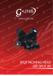
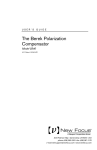
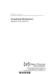
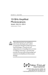
USER’S GUIDE Nanosecond Photodetectors Models 1621 & 1623 These photodetectors are sensitive to electrostatic discharges and could be permanently damaged if subjected even to small discharges. Ground yourself adequately prior to handling these detectors or making connections. A ground strap provides the most effective grounding and minimizes the likelihood of electrostatic damage 3635 Peterson Way • Santa Clara, CA 95054 • USA phone: (408) 980-5903 • fax: (408) 987-3178 e-mail: [email protected] • www.newfocus.com Warranty Newport Coporation guarantees its products to be free of defects for one year from the date of shipment. This is in lieu of all other guarantees, expressed or implied, and does not cover incidental or consequential loss. Information in this document is subject to change without notice. Copyright 2012, 2001-1998, Newport Corporation. All rights reserved. The New Focus logo and symbol are registered trademarks of Newport Corporation Document Number 162107 Rev. D Contents Operation 5 Introduction . . . . . . . . . . . . . . . . . . . . . . . . . . . . . . . . . . . . . . . . . . . 5 Using the Photodetector . . . . . . . . . . . . . . . . . . . . . . . . . . . . . . . . 7 Conserving Signal Strength . . . . . . . . . . . . . . . . . . . . . . . . . . . . . 8 Supplying your own load resistor. . . . . . . . . . . . . . . . . . . . . . . . 9 Checking and Replacing the Battery . . . . . . . . . . . . . . . . . . . . 10 General Features and Principles 11 Photoreceiver Circuitry . . . . . . . . . . . . . . . . . . . . . . . . . . . . . . . . . 11 Frequency and Time Response . . . . . . . . . . . . . . . . . . . . . . . . . . 11 Using Filters and Optical Fiber 15 Characteristics 17 Physical Specifications . . . . . . . . . . . . . . . . . . . . . . . . . . . . . . . . . .17 Photodetector Specifications . . . . . . . . . . . . . . . . . . . . . . . . . . . .18 Customer Service 19 Technical Support . . . . . . . . . . . . . . . . . . . . . . . . . . . . . . . . . . . . . .19 Service . . . . . . . . . . . . . . . . . . . . . . . . . . . . . . . . . . . . . . . . . . . . . . . . .19 Nanosecond Photodetectors Contents • 3 4 • Contents Operation Introduction The Model 162X is a general-purpose battery-powered photodetector for measuring optical signals down to nanosecond time scales. There are two versions of the Model 162X detector, each based on a different photodetector diode: Model Wavelength Type Diam. 1621 350–1000 nm silicon/PIN 0.8 mm 1623 800–1700 nm InGaAs/PIN 0.1 mm (with a 1.5mm ball lens) Complete specifications for the Model 162X nanosecond photodetectors begin on page 17. This product is ideal for detecting light pulses or monitoring optical signals from DC to several hundred MHz where an electronic amplifier is not required. The large-diameter detectors and the DC response make alignment and operation of the Model 162X easy. Figure 1 shows the typical responsivity curves for the photodetectors used in the Models 1621 and 1623. Nanosecond Photodetectors Operation • 5 1.0 Model 1623 0.8 Responsivity, A/W Figure 1: Typical responsivities of Model 1621 and Model 1623 0.6 Model 1621 0.4 0.2 0.0 200 400 600 800 1000 1200 Wavelength, nm 1400 1600 1800 2000 Each Model 162X photodetector runs off a single 9-volt alkaline battery. The photoreceiver’s slim casing, shown below, makes it easy to position it in a set-up between closely spaced optics. The switches and BNC output connector are located on top of the receiver for easy access. Figure 2: Model 162X casing Power switch Battery-check LED Load-resistor switch Output (BNC) Photodetector 8-32 (M4) Mounting threads A full mechanical diagram of the Model 162X casing is available on page 17. 6 • Operation Using the Photodetector 1. Check the battery voltage. The Model 162X is powered by a single 9-volt alkaline battery. To check the battery condition, push the red power switch to the BATT CHK position. If the green LED lights up, the battery is in good condition; if the LED does not light, the battery needs to be replaced (see page 10). 2. Mount the photodetector. Use the 8-32 thread (M4 for metric versions) on the bottom of the casing to mount the photoreceiver to a post or pedestal. The threading is seated in a non-conductive plastic pad to reduce the electrical noise associated with ground loops. Be careful not to over-tighten when attaching the casing to a post or pedestal, or the threaded insert can strip out of the plastic pad. 3. Connect the detector output. Connect your voltmeter, oscilloscope, or other instrument to the Output BNC connector on top of the detector. 4. Turn the power switch to “on.” The output voltage should register on your scope or instrument. 5. Align an optical beam onto the detector. Be careful to keep the optical power under the maximum optical power of 50 mW to avoid damaging the photodetector. 6. Select the load. Use the black switch on top of the detector to set the load to 50 , 10 k, or Open. (Select Open if you are providing an external load resistor. See “Supplying your own load resistor” on page 9.) 7. Turn the detector off. When you are finished with the detector, return the power switch to the “off” position. Nanosecond Photodetectors Operation • 7 Conserving Signal Strength If you have a low-power signal, 50 of transimpedance gain can lead to very small output voltages. If you need to conserve signal strength, it is important to focus your optical beam onto the photodiode. Adjusting the photodiode position for optimal signal is best performed as a two-step procedure: 1. Set the load resistance to 10 k or Open. 2. Hook the detector output directly into an oscilloscope or other voltage-measurement device with a large input impedance. 3. Adjust the photodiode position (in both transverse and focus directions) for maximum DC voltage. For optical signal levels above about 1 mW (at 10 k), the voltage will saturate. Remember, the output voltage can only rise up to the battery voltage—9 V when the battery is fresh. If you use the 1-M input impedance of an oscilloscope, saturation is even easier to reach. 4. Select the 50- resistor, or supply your own small load resistance suitable to your gain and frequency-response requirements. Make fine adjustments to the photodiode position until the maximum signal is achieved. To compute the approximate output voltage for a given input optical power use the relationship Vout = Pin · R · G, where Pin is the input optical power in watts, R is the photodetector’s responsivity in A/W (see page 6 for typical responsivities), and G is the load resistance (V/ A). For example, with 10 mW of optical power, a responsivity of 0.5 A/W, and with the load set to 50 , the photodetector will produce an output voltage of approximately (10 mW) · (0.5 A/W) · (50 V/A) = 0.25 V. 8 • Operation Supplying your own load resistor At high frequencies, typical resistors begin to exhibit parasitic inductance and capacitance. For instance, if you want to operate on the Open setting and supply your own 100- resistor, you might be tempted to use a standard carbon-film resistor soldered across the terminals of a BNC tee. The problem with this approach is that the parasitic inductance of such a home-made resistor will cause a significant change in the impedance at high frequencies. So, for best results you may need to buy a precision load resistor that is optimized for high-frequency use. You must also watch out for impedance mismatch problems. The internal transmission line from the photodiode to the BNC output has a characteristic impedance of 50 . This has been chosen for best compatibility with 50- impedance equipment. If you terminate this transmission line with a non-50- load, you should expect degraded frequency response. When you use 50- impedance equipment, you should switch the nanosecond photodetector into the Open position. If you leave the internal 50- resistor switched in, the photocurrent will be divided between the two loads, cutting your signal in half. If you leave the internal 10-k resistor switched in, it will have little effect, as the 50- load will draw the majority of the photocurrent. DC blocking devices are a potential source of confusion. Some sensitive high frequency equipment requires 0 V at DC input. In this case, we recommend that you put a high-frequency DC blocking load between the nanosecond detector and your equipment. If so, you must supply a DC path to ground for your photocurrent. This is easiest to do by switching in the photodetector’s 50- internal load resistor. If you switch in the 10-k load resistor, you Nanosecond Photodetectors Operation • 9 must be certain that the circuit does not saturate itself on the DC level. Checking and Replacing the Battery The Model 162X is powered by a single, standard 9-volt battery. The battery lifetime depends on the load resistor and on the optical input power to the photodetector. Under normal operating conditions the battery lifetime will typically be greater than 500 hours. To check the condition of the battery, push the red switch to the BATT CHK position. If the green LED lights up, the battery is in good condition. When the battery voltage falls below about 6.5 volts, the green LED will not light up, and the battery should be replaced. Replacing the Battery 1. Turn the red power switch to “off” to prevent damage to the receiver. 2. Remove the screw on the back of the photodetector casing and remove the back cover. 3. Unplug the old battery. 4. Install a new 9-volt alkaline battery. 5. Reinstall the back cover. 6. Test the new battery’s status by pushing the power switch to the BATT CHK position. 10 • Operation General Features and Principles Photoreceiver Circuitry The circuitry inside the Model 162X consists of a reverse-biased photodetector and a load resistor with three settings: 50 , 10 k, and Open. The 50- setting has 50-V/A sensitivity and can be used to achieve the 1-nanosecond response time. The 10-k setting has a reduced time response but gives a higher sensitivity (10,000 V/A) and can be used for alignment purposes and for detecting low-power pulses. The Open setting allows you to hook-up your own external load resistor and choose the best gain-bandwidth combination for your application. Figure 3: Functional schematic of the Model 162X circuitry +V Batt Chk ON LED Battery Check Circuit OFF Output 10 kΩ Open 50 Ω Frequency and Time Response The nanosecond photodetector circuitry is quite straightforward, consisting only of the photodiode, battery bias and a selectable load resistor. The speed limitation of the circuit is established by the junction capacitance of the photodiode and the load resistance Nanosecond Photodetectors General Features and Principles • 11 Figure 4: Typical frequency response for the Model 1623 on the 50-¾ setting Gain (10 dB/div) value. Figures 4 and 5 give typical frequency responses and pulse responses for the Model 162X photodetector. 0 100 200 300 400 500 600 Frequency, MHz When performing high-speed measurements, impedance-matching effects between your measurement apparatus and the photo-detector must be taken into consideration in order to achieve optimal high-speed response. Typical laboratory measurement equipment may prevent you from achieving nanosecond response times. BNC connectors do not match 50- transmission lines well for frequencies above 100 MHz. The frequency response is therefore not flat between 100 MHz and 500 MHz. Above 500 MHz, the situation can be worse, with typical BNC connectors and cables proving to be quite lossy. Therefore, while the time response of the nanosecond detector is quite fast, it is not expected to provide flat frequency response in the 100-MHz to 500-MHz regime. Selecting the internal 50- resistor will usually allow you to achieve a response speed which is limited by your detection equipment. Typical laboratory oscilloscopes, for instance, have only 10-MHz to 100-MHz bandwidth. When you select the 10-k 12 • General Features and Principles resistor, the speed is RC limited, and the response speed will typically be 50 ns. Figure 5: Typical pulse response for the (a) Model 1621 and (b) Model 1623 photodetectors (a) Model 1621 0 2 4 Time (ns) 6 8 10 (b) Model 1623 0 2 4 Time (ns) 6 8 10 A 0.15-ps pulse at 1.06 µm was used to test the photodetectors, and the output was measured using a 12-GHz oscilloscope. Nanosecond Photodetectors General Features and Principles • 13 14 • General Features and Principles Using Filters and Optical Fiber New Focus offers accessories, sold separately, to attach a 1"- diameter filter or an optical fiber to the detector. Both accessories attach to the casing using the 1.04-32 threads located in the casing around the detector. Note that the accessories are also compatible with two other New Focus products, the Model 203X large-area photoreceiver and the Model 215X femtowatt photoreceiver. The Model 1280 1" filter holder allows you to mount a 1"- diameter optic in front of the photodetector. For instance, you can mount a colored glass filter to remove unwanted wavelengths or a neutral-density filter to attenuate the optical power incident on the photodetector. The Model 1280 has a plastic ring for mounting a filter that is up to about 0.25" (6.4-mm) thick. A thicker optic can be held in place using the 6-32 nylon-tipped set screw. Use a 1/16" or 1.5-mm Allen key or ball-driver to adjust the set screw. The Model 1281 FC fiber adapter allows you to connect an FC connectorized fiber to the front of the photodetector. The coupling efficiency of light from an optical fiber to the Model 1623 photodetector is typically 70% or greater. The coupling efficiency is less than unity because of the small detector size and small variations in the mechanical position of the detector and the fiber. See Figure 6 for drawings of these two accessories. A variety of fiber couplers, fiber collimators and pigtails are also available from New Focus. Nanosecond Photodetectors Using Filters and Optical Fiber • 15 Figure 6: Model 1280 1" filter holder and the Model 1281 FC fiber adapter holes for tightening 1.04-32 thread Retaining ring for holding 1" or 25-mm optics. 0.1 (3.23" ) 0.6 (15 3" .9) 6-32 nylon-tipped setscrew for holding 1" or 25-mm optics. dia. 1.30" (33.0) Model 1280 patent pending 1.04-32 thread holes for tightening 0.3 (8.95" ) 0.1 (4.89" ) FC connector Model 1281 16 • Using Filters and Optical Fiber Characteristics Physical Specifications Figure 7: Mechanical drawing of the Model 162X casing 2.50 (63.5) 1.16 (29.5) Battery check LED Output (BNC) Load resistor switch Power switch 1.040-32 Threaded hole 4.03 (102.3) 1.00 (25.4) 1.25 (31.8) 8-32 (M4) Threaded insert Nanosecond Photodetectors Characteristics • 17 Photodetector Specifications Model # 1621 1623 350-1000 nm 800-1700 nm Silicon/PIN InGaAs/PIN 0.8 mm 0.1 mm (with 1.5mm-diameter ball lens) Typical Max. Responsivity 0.55 A/W (at 800 nm) 1.0 A/W (at 1600 nm) Maximum Optical Power 50 mW 50 mW 50 , 10 k, and Open (user provided) 50 , 10 k, and Open (user provided) 1 nanosecond (50- setting) 1 nanosecond (50- setting) Typical detector capacitance 3 pF 0.8 pF Electrical Output Connector BNC BNC One 9-volt alkaline battery One 9-volt alkaline battery >500 hours >500 hours Wavelength Range Detector Material/Type Detector Diameter Load Resistors Typical Rise Time Power Requirements Typical Battery Lifetime 18 • Characteristics Customer Service Technical Support Information and advice about the operation of any New Focus product is available from our applications engineers. For quickest response, ask for “Technical Support” and know the model and serial number for your product. Hours: 8:00–5:00 PST, Monday through Friday (excluding holidays). Toll Free: 1-866-NUFOCUS (1-866-683-6287) (from the USA & Canada only) Phone: (408) 980-5903 Support is also available by fax and email: Fax: (408) 987-3178 Email: [email protected] We typically respond to faxes and email within one business day. Service In the event that your photodetector malfunctions or becomes damaged, please contact New Focus for a return authorization number and instructions on shipping the unit back for evaluation and repair. Nanosecond Photodetectors Customer Service • 19 20 • Customer Service