1
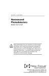
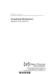
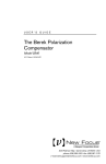
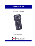
USER’S GUIDE
High-Dynamic-Range
Power Sensors
Models 2101 & 2103
2584 Junction Ave. • San Jose, CA 95134-1902 • USA
phone: (408) 919–1500
e-mail: [email protected] • www.newfocus.com
Warranty
New Focus, Inc. guarantees its products to be free of defects for one year from
the date of shipment. This is in lieu of all other guarantees, expressed or implied,
and does not cover incidental or consequential loss.
Information in this document is subject to change without notice.
Copyright 2003, 2002, 2001–1998, New Focus, Inc. All rights reserved.
The
NEW FOCUS, Inc.
logo and NEW FOCUS, Inc. are registered trademarks of
Document Number 210018 Rev. C
Contents
Operation
5
Introduction . . . . . . . . . . . . . . . . . . . . . . . . . . . . . . . . . . . . . . . . . . . 5
Basic Operating Information . . . . . . . . . . . . . . . . . . . . . . . . . . . . 6
Details of Operation . . . . . . . . . . . . . . . . . . . . . . . . . . . . . . . . . . . . 6
Characteristics
13
Physical Specifications . . . . . . . . . . . . . . . . . . . . . . . . . . . . . . . . . 13
Characteristics. . . . . . . . . . . . . . . . . . . . . . . . . . . . . . . . . . . . . . . . . 14
Customer Service
17
Technical Support . . . . . . . . . . . . . . . . . . . . . . . . . . . . . . . . . . . . . 17
Service . . . . . . . . . . . . . . . . . . . . . . . . . . . . . . . . . . . . . . . . . . . . . . . . 17
Models 2101 & 2103
Contents • 3
4 • Contents
NEW FOCUS, Inc.
Operation
Introduction
Models 2101 and 2103 High-Dynamic-Range Power
Sensors are sensitive optical receivers with logarithmic
conversion circuitry to provide an analog output
spanning a range of more than 70 dB of optical input
power. Designed for use in swept-wavelength optical
loss measurement, the fast rise and fall times allow
measurements at speeds of 100 nm/s and beyond. For
Model 2103, the provided calibration data enables
accurate absolute power measurement over the wavelength range from 1520 nm to 1620 nm.
Outside of the calibrated band, both the Model 2101
and Model 2103 work well as relative power sensors.
The logarithmic output provides a conversion gain of
50 mV/dB of optical power, so the full range of the sensor can be converted to a digital signal with better than
0.01-dB resolution using a single
14-bit, 5-V conversion. This simplifies data collection,
eliminating the need for user-controlled gain switching and multiple-laser sweeps. As a result, data can be
taken more quickly and without the added accuracy
concerns that result from stitching errors between
multiple sweeps.
The fast analog response is also useful for viewing
high-range signals on an oscilloscope, making the
Model 2101 and 2103 good tools for general lab use.
Multiple units can be bolted together and their power
Models 2101 & 2103
Operation • 5
cables daisy-chained for testing of multi-channel
devices and rack mounting.
Basic Operating Information
1. Multiple units may be bolted together using screws
found in threaded storage holes in the bottom of the
unit. Power connections can be daisy-chained from
one unit to the next using the short cables provided.
2. The Model 2101 accepts free space light input;
FC/PC and FC/APC fiber inputs are available with the
Model 1281 fiber adapter accessory. The Model 2103
accepts both FC/PC and FC/APC input connectors.
3. A ±15-V, 75-mA power supply is required.
In daisy-chained applications with N power sensors,
the power supply should be rated for N times 75 mA.
4. The output is an analog voltage with a gain
of 50 mV/dB of input light. For the Model 2101,
a 3.5-V output typically corresponds to
approximately 2 dBm of input optical power
at 920 nm. A 3.5-V output corresponds to
approximately 0 dBm of input power at
1550 nm for the Model 2103.
5. For the Model 2103, calibration information for
precise measurements in the 1520-nm to 1620-nm
range are provided on a sheet of paper found in the
back of the manual.
Details of Operation
Optical Input
The Model 2101 accepts both free space and FC fiber
input. A 5-mm diameter photodiode makes the free
space light easy to align.
6 • Operation
NEW FOCUS, Inc.
The Model 2103 accepts both FC/PC and FC/APC input
connectors. The fiber illuminates a 1-mm photodiode
at sufficiently close range so that all the light is
detected from both fiber types. The fiber is perpendicular to the diode so that the non-angle-polished input
fibers result in the specified polarization dependence
of <0.02 dB.
The typical wavelength dependence of the response is
shown in Figure 1 for Model 2101 and Figure 2 for
Model 2103, respectively. The vertical axis is in optical
dB, and the horizontal axis is in optical wavelength µm.
Figure 1:
Wavelength
response of
Model 2101 vs.
wavelength.
0
dB
–2
–4
–6
–8
0.20
0.40
0.60
0.80
1.00
1.20
Wavelength, µm
Figure 2:
Wavelength
response of
Model 2103 vs.
wavelength.
2
0
-2
dB
-4
-6
-8
-10
-12
0.7
0.9
1.1
1.3
1.5
1.7
1.9
Wavelength, µm
Models 2101 & 2103
Operation • 7
Calibration Data (Model 2103 Only)
To correct for wavelength response of the photodiode,
calibration information is provided on a sheet of paper
found in the back of the manual. These are the offsets
(in volts) which must be subtracted from measured
values in order for a 0-dBm input to produce 0 V at the
output. Input optical power is then given by
P(dBm) = 20 x ( Vmeas – Vcal)
Warm-up Time
Active temperature stabilization of the photodiode
and critical circuit components requires a warm-up
time of about five minutes for full accuracy. Within
this period, the status light (for Model 2103) changes
from red to green and the output varies by several dB
as the temperature stabilizes. Failure of the status light
to turn green indicates the ambient temperature is
outside the operating range, and Model 2103 may not
give accurate readings. Model 2101 has no status light.
Output Signal
The output of the Models 2101 and 2103 is an analog
voltage with a gain of 50 mV per dB of input light. For
Model 2101, a 3.5-V output corresponds to
approximately 2 dBm of input power at 920 nm; the
accuracy degrades for signals outside the specified
range of 0.4 V to 3.7 V (-60 dBm to +6 dBm). For the
Model 2103, a 3.5-V output corresponds to
approximately 0 dBm of input power at 1550 nm.
While the output range is about -0.2 V to 3.75 V
(-74 dBm to +5 dBm), accuracy degrades for signals
outside the specified range of 0.4 V to 3.7 V (-62 dBm
to +4 dBm). The unit must be connected to a highimpedance load; it cannot drive a 50-ohm load.
8 • Operation
NEW FOCUS, Inc.
Measurement Speed
The Models 2101 and 2103 have three filter settings (1,
5, and 25 kHz) to reduce noise when speed of response
is not critical. The fastest setting results in a 0-100%
small signal rise time of 30 µs and an analog
bandwidth in excess of 25 kHz. At this speed, the
Models 2101 and 2103 can be used to measure narrow
optical filters at wavelength sweep speeds of 100 nm/s.
To determine whether a slower filter setting can be
used for swept-wavelength measurements, compare a
measurement of the device under test at a faster sweep
speed to one at a slower sweep speed (e.g., four times
slower). If the faster measurement does not distort the
result, the filter can be used.
Cross-over Detail
-28
-29
-29
-29.5
-30
-30
dBm
Figure 3:
Close-up detail
of crossover
point for a sinewave input
dBm
The Models 2101 and 2103 employ fast switching to
achieve essentially seamless range-changing between
two gain levels. This feature results in slight
discontinuities (of both signal and noise) at the
crossover point near the output level of -29 dBm for
Model 2101 and 1.95 V (-31 dBm) for Model 2103.
Figure 3 shows an example of the crossover. This will
be insignificant for most applications but should be
kept in mind.
-31
-32
-31
-33
-31.5
-34
-3
-2
-1
0
Time (ms)
Models 2101 & 2103
-30.5
1
2
3
-32
-0.3
-0.2
-0.1
0
0.1
0.2
0.3
Time (ms)
Operation • 9
Noise Levels
The electrical noise voltage present at the output
divided by the gain (50 mV/dB) of the power sensor
represents the noise referred to the input. A plot of this
is shown in Figure 4 for the 25-kHz filter setting. Note
the discontinuity at the crossover.
10
1
rms noise level (dB)
Figure 4:
Typical noise of
the Model 2103
versus signal
level
0.1
0.01
0.001
0
10
20
30
40
50
60
70
|dBm|
10 • Operation
NEW FOCUS, Inc.
Multi-Channel Testing:
Ganging Multiple Units
Multiple units can be bolted together to help maintain
an orderly benchtop or to mount in a rack. Screws for
this are located in storage holes in the bottom of the
unit; these screws fit in the mating tabs (see Figure 5).
When bolted together, the short power cables
provided with each unit are used to daisy chain the
power connections so a single supply can power
multiple units. The New Focus Model 0901 15-V
Power Supply can power a total of nine units (four
from each of the two 300-mA outputs, and one from
the 100-mA output.)
Figure 5:
Ganging of
Model 2103,
front view.
Daisy-chained
power cables
not shown.
Mating Tab
Mating screws
stored on bottom
of each unit
Models 2101 & 2103
Operation • 11
12 • Operation
NEW FOCUS, Inc.
Characteristics
Physical Specifications
Figure 6:
Front, side and
back views of
the Model 2101
1.040-32 Thread for
FC Adapter #1281
Output BNC
3.89 (98.9)
3.25 (82.5)
1.75
(44.5)
3.00
(76.2)
Speed
Switch
3 Pin Female
Connector
2.0
(50.8)
1.50
(38.1)
2.86 (72.7)
Unless otherwise noted, dimensions are in inches
with metric dimensions in mm in parentheses.
Figure 7:
Front, side and
back views of
the Model 2103
Output BNC
3.89 (98.9)
3.25 (82.5)
2.86
(72.6)
FC Connector
1.50
(38.1)
3.00
(76.2)
Speed
Switch
3 Pin Female
Connector
2.86 (72.7)
Unless otherwise noted, dimensions are in inches
with metric dimensions in mm in parentheses.
Models 2101 & 2103
Characteristics • 13
Figure 8:
Single unit
configuration
Characteristics
Specification
Model 2101
Model 2103
Calibrated Wavelength Range
n/a
1520–1620 nm
Uncalibrated Wavelength Range
320~1060 nm
950–1650 nm
Photodiode Material
Si
InGaAs
Photodiode Diameter
5 mm
1 mm
Photodiode Window
Fusion bonded
borosilicate glass,
no AR coating
AR coating
optimized at
1550 nm
Bandwidth Settings (3 dB)
1, 5, 25 kHz
1, 5, 25 kHz
Transition Time 0–100%, 25 kHz setting
30 µs
30 µs
Maximum Power*
6 dBm
(920 nm typical)
4 dBm
rms Noise Floor*
-69 dBm
(920 nm typical)
-71 dBm
Calibrated Accuracy (0 dBm, 22˚ C)
n/a
0.1 dB
Relative Accuracy* (-61 to +4 dBm)
0.05 dB +63 pW
(920 nm typical)
0.05 dB + 40 pW
Optical Return Loss, Single-Mode APC
n/a
-50 dB
Polarization Dependence (FC/PC)
n/a
0.02 dB
Repeatability
n/a
0.01 dB
Crossover Level*
-29 dBm typical
-31 dBm typical
Crossover Transient
0.001 dB•ms
0.001 dB•ms
14 • Characteristics
NEW FOCUS, Inc.
Specification
Model 2101
Model 2103
Crossover Discontinuity
0.03 dB
0.03 dB
Temperature Drift
0.005 dB/˚ C typical
0.005 dB/˚ C typical
Output Type
Analog
Analog
Output Impedance
<1 Ω typical
<1 Ω typical
Output Reference Level* (23˚ C)
2 dBm = 3.5 V
(920 nm typical)
0 dBm = 3.5 ±0.005 V
Output Slope
0.5 V/decade
0.5 V/decade
Output Range
-0.2 to +3.75 V typ.
-0.2 to +3.75 V typ.
Input Connector
Free space plus fiber
adapter option
FC/PC or FC/APC
Power Consumption
±15 V, 75 mA
±15 V, 75 mA
Operating Temperature Range
15–35˚ C
15–35˚ C
*
Models 2101 & 2103
Taken at 1550 nm.
Characteristics • 15
16 • Characteristics
NEW FOCUS, Inc.
Customer Service
Technical Support
Information and advice about the operation of any
New Focus product is available from our applications
engineers. For quickest response, ask for “Technical
Support” and know the model and serial numbers for
your product.
Hours: 8:00–5:00 PST, Monday through Friday
(excluding holidays).
Toll Free: 1-866-NUFOCUS (1-866-683-6287)
(from the USA & Canada only)
Phone: (408) 919-1500
Support is also available by fax and email:
Fax: (408) 980-8883
Email: [email protected]
We typically respond to faxes and email within one
business day.
Service
In the event that the power sensor malfunctions or
becomes damaged, please contact New Focus for a
return authorization number and instructions on
shipping the unit back for evaluation and repair.
Models 2101 & 2103
Customer Service • 17
18 • Customer Service
NEW FOCUS, Inc.