1
Watchman 3100
User Manual
LR and SR Models
Optech Incorporated
Industrial Products Division
100 Wildcat Road
Toronto, Ontario, Canada M3J 2Z9
Telephone: (416) 661-5904
Facsimile: (416) 661-4168
Website: www.optech.on.ca
Document No. 290-000126/Rev A
November 2003
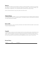
Warranty
This product is warranted to be free from defects in materials, parts and workmanship for a period of one year from the
date of delivery. It will conform to the current product specifications upon delivery. Misuse, improper handling, unauthorized repairs or modifications, or use of the system outside of specifications will void this warranty.
Failure to maintain the enclosure rating for this product will void this warranty.
Shipping Damage
This unit is inspected before shipment. As soon as you receive the unit from the carrier, and before operation, inspect the
unit for damage that may have occurred during shipment. If any damage is found, file a claim with the carrier and notify
your Optech representative immediately.
Return of Unit
Before returning this unit, contact your Optech representative to obtain a Return Authorization Number. Optech will not
accept units without an RA number.
Copyright
© Copyright 2003 by Optech Incorporated. All rights reserved. This item and the information contained herein are the
property of Optech Incorporated. No part of this document may be reproduced, transmitted, transcribed, stored in a
retrieval system, or translated into any language or computer language in any form or by any means otherwise, without
the express written permission of Optech Incorporated, 100 Wildcat Road, Toronto, Ontario, Canada M3J 2Z9.
Revision History
Revision
A
Date
Nov 03
Description
Release
Product Description Sheet
Product Name
Enclosure Type
Enclosure Serial No.
Rangefinder Serial No.
Software Versions No.
Options Supplied with This Product
Hand-Held Keypad
Sightglass - Unpressurized
120 V AC/DC Power Supply
Flange Gasket
120 VAC Heater and Power Supply
Sealing Gaskets
PG13.5 Conduit Entry Set
Bezel Gasket
Air Curtain
Universal Bracket
Spray Ring
Aritculating Bracket
Sightglass - Pressurized
Reflector Cluster
Special and Custom Features
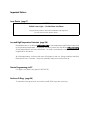
Important Notices
Laser Pointer (page 7)
CAUTION
Visible Laser Light - Do Not Stare Into Beam
Program laser pointer to OFF after installation and alignment.
Do not stare into laser pointer beam.
Low and High Temperature Protection (page 36)
Rangefinder turn-on is delayed without warning at low temperatures until heater warms unit
up to operating temperature; rangefinder and laser pointer are shut down without warning
at high temperatures until unit cools down. No data is transmitted or accepted when
rangefinder is shut down.
At cold temperatures, unit may take up to 45 minutes to turn on. Range readings may then
fluctuate for first 15 minutes. Accuracy gradually improves as unit warms up.
Remote Programming via PC
Use upper case letters only (press CAPS LOCK).
Enclosure O-Rings (page 54)
To maintain water-proof seal, save and re-install all O-rings after servicing.
Contents
Page
1 OVERVIEW. . . . . . . . . . . . . . . . . . . . . . . . . . . . . . . . . . . . . . . . . . . . . . . . . . . . . . . . . . . . . . . . . . . . . . . . 1
1.1 Terms Used in This Manual . . . . . . . . . . . . . . . . . . . . . . . . . . . . . . . . . . . . . . . . . . . . . . . . . . . . . . . . . . . . . . 1
1.2 Type Conventions . . . . . . . . . . . . . . . . . . . . . . . . . . . . . . . . . . . . . . . . . . . . . . . . . . . . . . . . . . . . . . . . . . . . . . 1
2 SYSTEM DESCRIPTION . . . . . . . . . . . . . . . . . . . . . . . . . . . . . . . . . . . . . . . . . . . . . . . . . . . . . . . . . . . . . . . . 3
2.1
2.2
2.3
2.4
Principle of Operation . . . . . . . . . . . . . . . . . . . . . . . . . . . . . . . . . . . . . . . . . . . . . . . . . . . . . . . . . . . . . . . . . .
Lasers . . . . . . . . . . . . . . . . . . . . . . . . . . . . . . . . . . . . . . . . . . . . . . . . . . . . . . . . . . . . . . . . . . . . . . . . . . . . . . .
Programming . . . . . . . . . . . . . . . . . . . . . . . . . . . . . . . . . . . . . . . . . . . . . . . . . . . . . . . . . . . . . . . . . . . . . . . . .
Outputs. . . . . . . . . . . . . . . . . . . . . . . . . . . . . . . . . . . . . . . . . . . . . . . . . . . . . . . . . . . . . . . . . . . . . . . . . . . . . .
4
5
5
5
3 SAFETY . . . . . . . . . . . . . . . . . . . . . . . . . . . . . . . . . . . . . . . . . . . . . . . . . . . . . . . . . . . . . . . . . . . . . . . . . . 7
3.1 Visible and Infrared Laser . . . . . . . . . . . . . . . . . . . . . . . . . . . . . . . . . . . . . . . . . . . . . . . . . . . . . . . . . . . . . . . . 7
3.2 AC/DC Enclosure Power Supply (120 VAC Option) . . . . . . . . . . . . . . . . . . . . . . . . . . . . . . . . . . . . . . . . . . . . 8
4 SPECIFICATIONS . . . . . . . . . . . . . . . . . . . . . . . . . . . . . . . . . . . . . . . . . . . . . . . . . . . . . . . . . . . . . . . . . . . . 9
5 UNPACKING . . . . . . . . . . . . . . . . . . . . . . . . . . . . . . . . . . . . . . . . . . . . . . . . . . . . . . . . . . . . . . . . . . . . . 13
6 CABLING . . . . . . . . . . . . . . . . . . . . . . . . . . . . . . . . . . . . . . . . . . . . . . . . . . . . . . . . . . . . . . . . . . . . . . . . 15
6.1 Cable Conduits . . . . . . . . . . . . . . . . . . . . . . . . . . . . . . . . . . . . . . . . . . . . . . . . . . . . . . . . . . . . . . . . . . . . . . .
6.2 Signal and Data Isolation . . . . . . . . . . . . . . . . . . . . . . . . . . . . . . . . . . . . . . . . . . . . . . . . . . . . . . . . . . . . . . .
6.3 J3 Terminal Block . . . . . . . . . . . . . . . . . . . . . . . . . . . . . . . . . . . . . . . . . . . . . . . . . . . . . . . . . . . . . . . . . . . . .
6.3.1 External Trigger . . . . . . . . . . . . . . . . . . . . . . . . . . . . . . . . . . . . . . . . . . . . . . . . . . . . . . . . . . . . . . . . .
6.4 J2 RS-232C Serial Connector (Local Programming) . . . . . . . . . . . . . . . . . . . . . . . . . . . . . . . . . . . . . . . . . . . .
6.5 Serial Data Protocol . . . . . . . . . . . . . . . . . . . . . . . . . . . . . . . . . . . . . . . . . . . . . . . . . . . . . . . . . . . . . . . . . . .
15
16
16
17
17
18
7 MOUNTING . . . . . . . . . . . . . . . . . . . . . . . . . . . . . . . . . . . . . . . . . . . . . . . . . . . . . . . . . . . . . . . . . . . . . . 19
7.1 Mounting Elements . . . . . . . . . . . . . . . . . . . . . . . . . . . . . . . . . . . . . . . . . . . . . . . . . . . . . . . . . . . . . . . . . . . .
7.1.1 Mounting Bosses . . . . . . . . . . . . . . . . . . . . . . . . . . . . . . . . . . . . . . . . . . . . . . . . . . . . . . . . . . . . . . . .
7.1.2 Mounting Holes . . . . . . . . . . . . . . . . . . . . . . . . . . . . . . . . . . . . . . . . . . . . . . . . . . . . . . . . . . . . . . . .
7.1.3 Orientation of the Interface Module . . . . . . . . . . . . . . . . . . . . . . . . . . . . . . . . . . . . . . . . . . . . . . . . .
7.2 Mounting Configurations . . . . . . . . . . . . . . . . . . . . . . . . . . . . . . . . . . . . . . . . . . . . . . . . . . . . . . . . . . . . . . .
7.2.1 Surface Mounting and Alignment . . . . . . . . . . . . . . . . . . . . . . . . . . . . . . . . . . . . . . . . . . . . . . . . . . .
7.3 Other Mounting Configurations . . . . . . . . . . . . . . . . . . . . . . . . . . . . . . . . . . . . . . . . . . . . . . . . . . . . . . . . . .
19
19
19
19
20
20
20
8 INSTALLATION . . . . . . . . . . . . . . . . . . . . . . . . . . . . . . . . . . . . . . . . . . . . . . . . . . . . . . . . . . . . . . . . . . . . 21
8.1 Installation Procedure . . . . . . . . . . . . . . . . . . . . . . . . . . . . . . . . . . . . . . . . . . . . . . . . . . . . . . . . . . . . . . . . . . 21
8.2 Installation Drawings . . . . . . . . . . . . . . . . . . . . . . . . . . . . . . . . . . . . . . . . . . . . . . . . . . . . . . . . . . . . . . . . . . 23
8.3 Field Interface . . . . . . . . . . . . . . . . . . . . . . . . . . . . . . . . . . . . . . . . . . . . . . . . . . . . . . . . . . . . . . . . . . . . . . . . 25
9 ALIGNMENT PROCEDURES . . . . . . . . . . . . . . . . . . . . . . . . . . . . . . . . . . . . . . . . . . . . . . . . . . . . . . . . . . . . 27
9.1 Laser Pointer Method . . . . . . . . . . . . . . . . . . . . . . . . . . . . . . . . . . . . . . . . . . . . . . . . . . . . . . . . . . . . . . . . . . 28
9.2 Distance Method . . . . . . . . . . . . . . . . . . . . . . . . . . . . . . . . . . . . . . . . . . . . . . . . . . . . . . . . . . . . . . . . . . . . . 29
9.3 Retro-Reflector Method. . . . . . . . . . . . . . . . . . . . . . . . . . . . . . . . . . . . . . . . . . . . . . . . . . . . . . . . . . . . . . . . . 30
10 OPERATION . . . . . . . . . . . . . . . . . . . . . . . . . . . . . . . . . . . . . . . . . . . . . . . . . . . . . . . . . . . . . . . . . . . . . 33
10.1
10.2
10.3
10.4
Operating Steps . . . . . . . . . . . . . . . . . . . . . . . . . . . . . . . . . . . . . . . . . . . . . . . . . . . . . . . . . . . . . . . . . . . . .
Powering ON/OFF . . . . . . . . . . . . . . . . . . . . . . . . . . . . . . . . . . . . . . . . . . . . . . . . . . . . . . . . . . . . . . . . . . .
Laser Footprint . . . . . . . . . . . . . . . . . . . . . . . . . . . . . . . . . . . . . . . . . . . . . . . . . . . . . . . . . . . . . . . . . . . . . .
Accuracy . . . . . . . . . . . . . . . . . . . . . . . . . . . . . . . . . . . . . . . . . . . . . . . . . . . . . . . . . . . . . . . . . . . . . . . . . .
10.4.1 Accuracy and Repeatability. . . . . . . . . . . . . . . . . . . . . . . . . . . . . . . . . . . . . . . . . . . . . . . . . . . . . . .
10.4.2 Accuracy Restrictions . . . . . . . . . . . . . . . . . . . . . . . . . . . . . . . . . . . . . . . . . . . . . . . . . . . . . . . . . . .
10.4.3 Low-Temperature Start . . . . . . . . . . . . . . . . . . . . . . . . . . . . . . . . . . . . . . . . . . . . . . . . . . . . . . . . . .
33
34
34
34
34
35
35
10.5 Thermal Protection . . . . . . . . . . . . . . . . . . . . . . . . . . . . . . . . . . . . . . . . . . . . . . . . . . . . . . . . . . . . . . . . . . .
10.5.1 High-Temperature Rangefinder Protection. . . . . . . . . . . . . . . . . . . . . . . . . . . . . . . . . . . . . . . . . . . .
10.5.2 High-Temperature Laser Pointer Protection . . . . . . . . . . . . . . . . . . . . . . . . . . . . . . . . . . . . . . . . . . .
10.5.3 Rangefinder DC Heater . . . . . . . . . . . . . . . . . . . . . . . . . . . . . . . . . . . . . . . . . . . . . . . . . . . . . . . . . .
10.5.4 120 VAC Enclosure Heater (Option) . . . . . . . . . . . . . . . . . . . . . . . . . . . . . . . . . . . . . . . . . . . . . . . .
36
36
37
37
37
11 PROGRAMMING . . . . . . . . . . . . . . . . . . . . . . . . . . . . . . . . . . . . . . . . . . . . . . . . . . . . . . . . . . . . . . . . . . 39
11.1 Summary of Screens and Programmable Settings . . . . . . . . . . . . . . . . . . . . . . . . . . . . . . . . . . . . . . . . . . . .
11.1.1 Hand-Held Keypad . . . . . . . . . . . . . . . . . . . . . . . . . . . . . . . . . . . . . . . . . . . . . . . . . . . . . . . . . . . . .
11.1.2 Using the Programming Screens . . . . . . . . . . . . . . . . . . . . . . . . . . . . . . . . . . . . . . . . . . . . . . . . . . .
11.2 Programming the Laser Pointer . . . . . . . . . . . . . . . . . . . . . . . . . . . . . . . . . . . . . . . . . . . . . . . . . . . . . . . . . .
11.3 Main Menu Screen . . . . . . . . . . . . . . . . . . . . . . . . . . . . . . . . . . . . . . . . . . . . . . . . . . . . . . . . . . . . . . . . . . .
11.4 Format Screens . . . . . . . . . . . . . . . . . . . . . . . . . . . . . . . . . . . . . . . . . . . . . . . . . . . . . . . . . . . . . . . . . . . . . .
11.4.1 Measurement Units for Range Readings . . . . . . . . . . . . . . . . . . . . . . . . . . . . . . . . . . . . . . . . . . . . .
11.4.2 Power Menu . . . . . . . . . . . . . . . . . . . . . . . . . . . . . . . . . . . . . . . . . . . . . . . . . . . . . . . . . . . . . . . . . .
11.4.3 Range Resolution . . . . . . . . . . . . . . . . . . . . . . . . . . . . . . . . . . . . . . . . . . . . . . . . . . . . . . . . . . . . . .
11.4.4 Data . . . . . . . . . . . . . . . . . . . . . . . . . . . . . . . . . . . . . . . . . . . . . . . . . . . . . . . . . . . . . . . . . . . . . . . .
11.5 ANALOG Screens: 4-20 mA Analog Range Settings . . . . . . . . . . . . . . . . . . . . . . . . . . . . . . . . . . . . . . . . . .
11.6 Modes Screens . . . . . . . . . . . . . . . . . . . . . . . . . . . . . . . . . . . . . . . . . . . . . . . . . . . . . . . . . . . . . . . . . . . . . .
11.6.1 First/Last-Pulse Range Filter . . . . . . . . . . . . . . . . . . . . . . . . . . . . . . . . . . . . . . . . . . . . . . . . . . . . . . .
11.6.2 Filter Distance and Time-Out . . . . . . . . . . . . . . . . . . . . . . . . . . . . . . . . . . . . . . . . . . . . . . . . . . . . .
11.6.3 Trigger. . . . . . . . . . . . . . . . . . . . . . . . . . . . . . . . . . . . . . . . . . . . . . . . . . . . . . . . . . . . . . . . . . . . . . .
11.7 Set-Up Screens . . . . . . . . . . . . . . . . . . . . . . . . . . . . . . . . . . . . . . . . . . . . . . . . . . . . . . . . . . . . . . . . . . . . . .
11.7.1 Rate. . . . . . . . . . . . . . . . . . . . . . . . . . . . . . . . . . . . . . . . . . . . . . . . . . . . . . . . . . . . . . . . . . . . . . . . .
11.7.2 Offset . . . . . . . . . . . . . . . . . . . . . . . . . . . . . . . . . . . . . . . . . . . . . . . . . . . . . . . . . . . . . . . . . . . . . . .
11.7.3 Pointer . . . . . . . . . . . . . . . . . . . . . . . . . . . . . . . . . . . . . . . . . . . . . . . . . . . . . . . . . . . . . . . . . . . . . .
39
42
42
42
43
43
43
44
44
45
45
47
47
48
50
50
50
51
52
12 MAINTENANCE . . . . . . . . . . . . . . . . . . . . . . . . . . . . . . . . . . . . . . . . . . . . . . . . . . . . . . . . . . . . . . . . . . . 53
12.1 Enclosure Window Cleaning and Maintenance . . . . . . . . . . . . . . . . . . . . . . . . . . . . . . . . . . . . . . . . . . . . . .
12.1.1 Compatible Cleaning Agents . . . . . . . . . . . . . . . . . . . . . . . . . . . . . . . . . . . . . . . . . . . . . . . . . . . . . .
12.1.2 Graffiti Removal . . . . . . . . . . . . . . . . . . . . . . . . . . . . . . . . . . . . . . . . . . . . . . . . . . . . . . . . . . . . . . .
12.2 Enclosure O-Rings and Seals. . . . . . . . . . . . . . . . . . . . . . . . . . . . . . . . . . . . . . . . . . . . . . . . . . . . . . . . . . . .
12.3 Fuses. . . . . . . . . . . . . . . . . . . . . . . . . . . . . . . . . . . . . . . . . . . . . . . . . . . . . . . . . . . . . . . . . . . . . . . . . . . . . .
12.4 Storage . . . . . . . . . . . . . . . . . . . . . . . . . . . . . . . . . . . . . . . . . . . . . . . . . . . . . . . . . . . . . . . . . . . . . . . . . . . .
12.5 Returning the Watchman 3100 to the Factory . . . . . . . . . . . . . . . . . . . . . . . . . . . . . . . . . . . . . . . . . . . . . . .
53
53
54
54
55
55
55
13 TROUBLESHOOTING . . . . . . . . . . . . . . . . . . . . . . . . . . . . . . . . . . . . . . . . . . . . . . . . . . . . . . . . . . . . . . . 57
13.1
13.2
13.3
13.4
13.5
13.6
13.7
Error Codes . . . . . . . . . . . . . . . . . . . . . . . . . . . . . . . . . . . . . . . . . . . . . . . . . . . . . . . . . . . . . . . . . . . . . . . . .
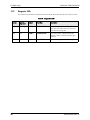
Diagnostic LEDs . . . . . . . . . . . . . . . . . . . . . . . . . . . . . . . . . . . . . . . . . . . . . . . . . . . . . . . . . . . . . . . . . . . . .
No Operation . . . . . . . . . . . . . . . . . . . . . . . . . . . . . . . . . . . . . . . . . . . . . . . . . . . . . . . . . . . . . . . . . . . . . . .
Intermittent Operation . . . . . . . . . . . . . . . . . . . . . . . . . . . . . . . . . . . . . . . . . . . . . . . . . . . . . . . . . . . . . . . .
Erratic/Fluctuating/Short Readings . . . . . . . . . . . . . . . . . . . . . . . . . . . . . . . . . . . . . . . . . . . . . . . . . . . . . . . .
Local Test . . . . . . . . . . . . . . . . . . . . . . . . . . . . . . . . . . . . . . . . . . . . . . . . . . . . . . . . . . . . . . . . . . . . . . . . . .
Servicing the Enclosure . . . . . . . . . . . . . . . . . . . . . . . . . . . . . . . . . . . . . . . . . . . . . . . . . . . . . . . . . . . . . . . .
13.7.1 Removing the Rangefinder from the Enclosure . . . . . . . . . . . . . . . . . . . . . . . . . . . . . . . . . . . . . . . .
13.7.2 Installing the Rangefinder in the Enclosure . . . . . . . . . . . . . . . . . . . . . . . . . . . . . . . . . . . . . . . . . . .
57
58
59
60
61
62
63
63
64
14 APPENDIX: PRODUCT INFORMATION . . . . . . . . . . . . . . . . . . . . . . . . . . . . . . . . . . . . . . . . . . . . . . . . . . . 67
14.1 Hand-Held Programmer Communications Configuration . . . . . . . . . . . . . . . . . . . . . . . . . . . . . . . . . . . . . .
14.2 Options. . . . . . . . . . . . . . . . . . . . . . . . . . . . . . . . . . . . . . . . . . . . . . . . . . . . . . . . . . . . . . . . . . . . . . . . . . . .
14.2.1 Hand-Held Programmer . . . . . . . . . . . . . . . . . . . . . . . . . . . . . . . . . . . . . . . . . . . . . . . . . . . . . . . . .
14.2.2 120 VAC Power Supply. . . . . . . . . . . . . . . . . . . . . . . . . . . . . . . . . . . . . . . . . . . . . . . . . . . . . . . . . .
14.2.3 120 VAC Heater . . . . . . . . . . . . . . . . . . . . . . . . . . . . . . . . . . . . . . . . . . . . . . . . . . . . . . . . . . . . . . .
14.2.4 PG 13.5 Conduit Entry Set. . . . . . . . . . . . . . . . . . . . . . . . . . . . . . . . . . . . . . . . . . . . . . . . . . . . . . . .
14.2.5 Air Curtain . . . . . . . . . . . . . . . . . . . . . . . . . . . . . . . . . . . . . . . . . . . . . . . . . . . . . . . . . . . . . . . . . . .
14.2.6 Spray Ring. . . . . . . . . . . . . . . . . . . . . . . . . . . . . . . . . . . . . . . . . . . . . . . . . . . . . . . . . . . . . . . . . . . .
14.2.7 Sightglass and Gaskets. . . . . . . . . . . . . . . . . . . . . . . . . . . . . . . . . . . . . . . . . . . . . . . . . . . . . . . . . . .
14.2.8 Sightglasses . . . . . . . . . . . . . . . . . . . . . . . . . . . . . . . . . . . . . . . . . . . . . . . . . . . . . . . . . . . . . . . . . . .
67
68
68
68
68
69
69
69
69
70
14.2.8.1 Sightglass Installation . . . . . . . . . . . . . . . . . . . . . . . . . . . . . . . . . . . . . . . . . . . . . . . . . .
14.2.9 Articulating Bracket. . . . . . . . . . . . . . . . . . . . . . . . . . . . . . . . . . . . . . . . . . . . . . . . . . . . . . . . . . . . .
14.2.9.1 Articulating Bracket Installation . . . . . . . . . . . . . . . . . . . . . . . . . . . . . . . . . . . . . . . . . .
14.2.10 LEXAN Window . . . . . . . . . . . . . . . . . . . . . . . . . . . . . . . . . . . . . . . . . . . . . . . . . . . . . . . . . . . . . .
14.2.11 Reflector Clusters . . . . . . . . . . . . . . . . . . . . . . . . . . . . . . . . . . . . . . . . . . . . . . . . . . . . . . . . . . . . .
14.3 Electrical Interface Detail . . . . . . . . . . . . . . . . . . . . . . . . . . . . . . . . . . . . . . . . . . . . . . . . . . . . . . . . . . . . . .
71
72
73
74
74
74
List of Figures
Page
Figure 1: Watchman 3100 Level Monitor . . . . . . . . . . . . . . . . . . . . . . . . . . . . . . . . . . . . . . . . . . . . . . . . . . . . . . . . . . . . 3
Figure 2: Main Features of the Watchman 3100 . . . . . . . . . . . . . . . . . . . . . . . . . . . . . . . . . . . . . . . . . . . . . . . . . . . . . . . 4
Figure 3: IEC Eyesafety Labels . . . . . . . . . . . . . . . . . . . . . . . . . . . . . . . . . . . . . . . . . . . . . . . . . . . . . . . . . . . . . . . . . . . . 8
Figure 4: Unit Top View (205-000106) . . . . . . . . . . . . . . . . . . . . . . . . . . . . . . . . . . . . . . . . . . . . . . . . . . . . . . . . . . . . 23
Figure 5: Unit Cross-Section (205-000106) . . . . . . . . . . . . . . . . . . . . . . . . . . . . . . . . . . . . . . . . . . . . . . . . . . . . . . . . . 24
Figure 6: Unit Bottom View (205-000106) . . . . . . . . . . . . . . . . . . . . . . . . . . . . . . . . . . . . . . . . . . . . . . . . . . . . . . . . . . 24
Figure 7: Unit Front View (205-000106) . . . . . . . . . . . . . . . . . . . . . . . . . . . . . . . . . . . . . . . . . . . . . . . . . . . . . . . . . . . 25
Figure 8: Field Interface Board Schematic (230-010073) . . . . . . . . . . . . . . . . . . . . . . . . . . . . . . . . . . . . . . . . . . . . . . . 25
Figure 9: Using Retro-Reflectors with Laser Beam . . . . . . . . . . . . . . . . . . . . . . . . . . . . . . . . . . . . . . . . . . . . . . . . . . . . 31
Figure 10: Footprint of Rangefinder Laser Beam . . . . . . . . . . . . . . . . . . . . . . . . . . . . . . . . . . . . . . . . . . . . . . . . . . . . . 34
Figure 11: Thermal Protection . . . . . . . . . . . . . . . . . . . . . . . . . . . . . . . . . . . . . . . . . . . . . . . . . . . . . . . . . . . . . . . . . . . 36
Figure 12: Watchman Programming Screens . . . . . . . . . . . . . . . . . . . . . . . . . . . . . . . . . . . . . . . . . . . . . . . . . . . . . . . . 40
Figure 13: Rangefinder Connector Panel (Inside Enclosure) . . . . . . . . . . . . . . . . . . . . . . . . . . . . . . . . . . . . . . . . . . . . . 63
Figure 14: Options for Optech Level Monitors and Object Positioners . . . . . . . . . . . . . . . . . . . . . . . . . . . . . . . . . . . . . 68
Figure 15: Spray Ring Flange Accessory . . . . . . . . . . . . . . . . . . . . . . . . . . . . . . . . . . . . . . . . . . . . . . . . . . . . . . . . . . . . 69
Figure 16: Sightglass and Retainer Flange Accessory . . . . . . . . . . . . . . . . . . . . . . . . . . . . . . . . . . . . . . . . . . . . . . . . . . 70
Figure 17: Sightglass and Gasket Installation (Front View) . . . . . . . . . . . . . . . . . . . . . . . . . . . . . . . . . . . . . . . . . . . . . . 71
Figure 18: Articulating Bracket, Front View . . . . . . . . . . . . . . . . . . . . . . . . . . . . . . . . . . . . . . . . . . . . . . . . . . . . . . . . . 72
Figure 19: Articulating Bracket, Side View . . . . . . . . . . . . . . . . . . . . . . . . . . . . . . . . . . . . . . . . . . . . . . . . . . . . . . . . . . 73
Figure 20: Electrical Interface Detail . . . . . . . . . . . . . . . . . . . . . . . . . . . . . . . . . . . . . . . . . . . . . . . . . . . . . . . . . . . . . . 74
List of Tables
Page
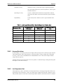
Table 1: Terminal Block Assignments . . . . . . . . . . . . . . . . . . . . . . . . . . . . . . . . . . . . . . . . . . . . . . . . . . . . . . . . . . . . . .
Table 2: J2 RS-232C Connector Pinout . . . . . . . . . . . . . . . . . . . . . . . . . . . . . . . . . . . . . . . . . . . . . . . . . . . . . . . . . . . .
Table 3: Accuracy and Repeatability at Selected Measurement Update Rates . . . . . . . . . . . . . . . . . . . . . . . . . . . . . . . .
Table 4: Programmable Settings . . . . . . . . . . . . . . . . . . . . . . . . . . . . . . . . . . . . . . . . . . . . . . . . . . . . . . . . . . . . . . . . . .
Table 5: Common Programming Operations. . . . . . . . . . . . . . . . . . . . . . . . . . . . . . . . . . . . . . . . . . . . . . . . . . . . . . . . .
Table 6: Replaceable Fuses. . . . . . . . . . . . . . . . . . . . . . . . . . . . . . . . . . . . . . . . . . . . . . . . . . . . . . . . . . . . . . . . . . . . . .
Table 7: Troubleshooting Summary . . . . . . . . . . . . . . . . . . . . . . . . . . . . . . . . . . . . . . . . . . . . . . . . . . . . . . . . . . . . . . .
Table 8: Error Codes . . . . . . . . . . . . . . . . . . . . . . . . . . . . . . . . . . . . . . . . . . . . . . . . . . . . . . . . . . . . . . . . . . . . . . . . . . .
Table 9: Diagnostic LEDs . . . . . . . . . . . . . . . . . . . . . . . . . . . . . . . . . . . . . . . . . . . . . . . . . . . . . . . . . . . . . . . . . . . . . . .
Table 10: Terminal Block Pin Descriptions . . . . . . . . . . . . . . . . . . . . . . . . . . . . . . . . . . . . . . . . . . . . . . . . . . . . . . . . . .
16
17
35
41
42
55
57
57
58
75
Watchman 3100 User Manual
1
Overview
OVERVIEW
This manual provides installation, programming, operation and maintenance information for users
of the Watchman 3100 object positioner. Both the Watchman 3100LR and 3100SR models are
discussed in this manual. Unless otherwise stated, information applies to both models.
1.1
Terms Used in This Manual
To highlight important information, this manual uses the following signal words. Do not proceed
until you understand the information and have complied with any instructions:
1.2
DANGER
Death or serious injury.
WARNING
Potential for death or serious injury.
CAUTION
Potential for minor or moderate injury; unsafe practices.
NOTICE
Damage to equipment or loss of data; policy on safety of
personnel or protection of property.
IMPORTANT
Operation or maintenance suggestion; other useful information.
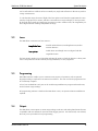
Type Conventions
This manual uses the following type conventions:
290-000126/Rev A/Nov 03
POINTER ON
Hardware labels
MAIN MENU
For text displayed on, or entered via, keypad or PC.
1
Overview
2
Watchman 3100 User Manual
290-000126/Rev A/Nov 03
Watchman 3100 User Manual
2
System Description
SYSTEM DESCRIPTION
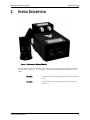
Figure 1: Watchman 3100 Level Monitor
The Watchman 3100 is a laser-based, non-contact measurement system designed for industrial
use as an object positioner. It is a member of Optech’s Series 3000 family of industrial instruments.
290-000126/Rev A/Nov 03
SR Model
Optimized for short-range applications typically less than
25 m.
LR Model
Optimized for long-range applications typically greater
than 25 m.
3
System Description
Watchman 3100 User Manual
SIDE VIEW
Interface
Module
FRONT VIEW
Window Assembly
Cable Conduits
Enclosure
Rc
Mounting Bosses
Rangefinder
Lenses
Tx
Laser Pointer
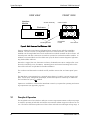
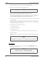
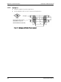
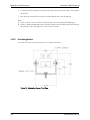
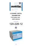
Figure 2: Main Features of the Watchman 3100
Figure 2 outlines the main features of the Watchman 3100 enclosure with the rangefinder
installed. The unit consists of a rangefinder housed in a sealed enclosure, with a window
installed over the rangefinder lenses and a small interface module mounted on the enclosure. All
external power and data connections are made to a printed circuit board inside this module. In
addition to a terminal block and a local RS-232C port, the board contains diagnostic light-emitting diodes (LEDs) and fuses.
Housed in a rugged, die-cast, aluminum enclosure, the Watchman 3100 is configured for versatile surface mounting in any orientation. Mounting bosses and internal mounting holes on the
base of the enclosure are provided for flexible installation.
The enclosure and the interface module are fully sealed to ensure dust- and water-proof operation.
The Watchman 3100 operates from a nominal input voltage of 24 VDC (120 VAC option available). Power input, analog data input/output, and RS-422 output are isolated up to 1000 VDC.
The local RS-232C port is not isolated.
Options are available to customize the Watchman 3100 for your particular operating and mounting requirements (see Appendix, page 67).
2.1
Principle of Operation
The rangefinder uses a laser diode to make non-contact range measurements to almost any target
or material, operating in both dark and well-lit environments without using retro-reflectors or mirrors. The narrow laser beam produces no false echoes and resolves small targets at long range. It
4
290-000126/Rev A/Nov 03
Watchman 3100 User Manual
System Description
can be reflected from a diffuse surface at virtually any angle and still return to the unit to produce
a range measurement.
To calculate the range, the time of flight of the laser pulse to and from the target/material is measured by a high-precision counter, and then converted into a range reading by a microprocessor.
By firing the laser rapidly and employing averaging to reduce random errors, the rangefinder produces high-resolution readings independent of range.
2.2
Lasers
The Watchman 3100 uses two laser sources:
Rangefinder laser
Invisible infrared beam (wavelength 905 nm) used to
measure distance
Laser pointer
Visible beam (wavelength 635 nm) aligned with the
rangefinder beam.
The laser pointer produces a red spot that indicates the point to which the distance is being measured. The pointer should be used only during installation, to verify alignment.
2.3
Programming
Embedded software enables you to customize many aspects of operation, with an optional
keypad providing a simple and convenient user interface. The unit can also be programmed via
PC or Palmtop computer.
A local, non-isolated RS-232C port can be used during installation to program and test the unit,
and to monitor range readings.
All programming software is built into the Watchman 3100; no separate software installation is
required.
2.4
Outputs
The Watchman 3100 outputs accurate range readings in RS-422 and analog data formats that are
compatible with most industrial control and data logging systems. A bi-directional, non-isolated,
RS-232C port is provided for local programming.
290-000126/Rev A/Nov 03
5
System Description
6
Watchman 3100 User Manual
290-000126/Rev A/Nov 03
Watchman 3100 User Manual
Safety
3
SAFETY
3.1
Visible and Infrared Laser
CAUTION
Visible Laser Light - Do Not Stare Into Beam
Use of controls or adjustments or performance of procedures other than those specified
herein may result in hazardous exposure to laser light.
Use of optical instruments with pointer may increase eye hazard.
Program laser pointer to OFF after installation and alignment.
The Watchman 3100 has two laser sources contained in the unit:
Invisible infrared (IR)
Used for range measurement
Visible beam
Used for alignment.
The infrared (IR) laser emits energy that is not visible to the human eye. It is designed as a Class
1M laser source as specified by IEC 60825-1:1993+A1:1997+A2:2001. In normal operation the
IR laser is not considered hazardous. In normal installation and use, a person may view the laser
light with the naked eye or with eyeglasses assisting vision.
The visible laser pointer is classified as a Class 2 laser product per IEC 60825-1:
1993+A1:1997+A2:2001. Class 2 denotes low power visible lasers or laser systems that, because
of normal human aversion responses, do not usually present a hazard. In normal installation and
use, a person may view the laser light with the naked eye or with eyeglasses assisting vision. The
laser pointer emits continuous visible laser light at a wavelength of 635 nm.
The laser pointer light has an optical power of less than 1 mW and a spot diameter of less than 15
mm at a range of 5 m. The laser pointer is co-aligned with the rangefinder beam, and projects a
red spot on any surface. Note that this beam spot may be hard to see in bright light.
When the two laser beams are considered together, the Watchman 3100 is considered a Class 2M
product per IEC 60825-1: 1993+A1: 1997+A2:2001. The Watchman 3100 is therefore labeled as
a Class 2M product; the two labels on the unit are shown in Figure 3. This labeling and classification system ensures that the Watchman 3100 complies with all requirements of the European eyesafety standard (IEC 608251: 1993+A1: 1997+A2:2001) and with the United States eyesafety
standard (21 CFR 1040, parts 10 and 11, and Laser Notice 50, dated July 2001).
As with many conventional light sources, there is some potential for hazard if the laser light is
viewed directly for long periods.
Do not use optical instruments such as binoculars or other devices that collect light while the
laser pointer is firing. As a standard laser precaution, do not stare directly into the laser, and do
not install the Watchman 3100 at eye level.
Use the laser pointer for alignment only, and not in normal operation. To prevent accidental
exposure to the laser beam, Optech strongly recommends programming the pointer OFF through
290-000126/Rev A/Nov 03
7
Safety
Watchman 3100 User Manual
software as soon as the Watchman 3100 is installed and aligned. As a precaution, the pointer
always defaults to OFF upon power-up.
Figure 3: IEC Eyesafety Labels
3.2
AC/DC Enclosure Power Supply (120 VAC Option)
WARNING
120 VAC Shock Hazard
Optional power supply can cause death or severe injury.
Do not open enclosure when unit powered. Only qualified personnel should handle
power supply and associated wires and connectors.
The optional AC/DC power supply converts an external 120 VAC power source into the 24 VDC
used internally by the Watchman 3100. The power supply is located inside the main enclosure,
and is not accessible during normal operation. The fuse for this device is located at F3 on the
interface board, covered by a reusable fuse cover.
120 VAC is present on the interface board at terminals 12 and 13 of the terminal block and pins
34 and 36 of the 40-pin edge connector (terminal 14 is chassis ground). Live voltages may also be
present at the power supply. When the Watchman 3100 is powered, do not touch the above connections.
8
290-000126/Rev A/Nov 03
Watchman 3100 User Manual
4
Specifications
SPECIFICATIONS
All specifications are subject to change without notice. For additional information and other
options, see appendix, page 67.
Measurement
Range 1
0.2 m to 250 m
0.2 m to 1,500 m with reflectors
Absolute accuracy 2
Within 2 cm
Operating accuracy 3
Within 5 mm
Repeatability 4
Within 3 mm
Resolution
1 mm
Rate
Programmable from 1 reading every 5 seconds to 20 readings per
second
Maximum reportable range
1,500 m
Units of measurement
Meters or feet
Zero reference point
Front surface of enclosure window frame
Outputs
Analog 5
4-20 mA; max. load 1,000 ohms; 1,000 VDC isolation
Serial RS-422
Transmit only; 1,000 VDC isolation
Serial RS-232C
Bi-directional; for test and setup only; not isolated
1.
2.
3.
4.
5.
Maximum ranges are typical and depend upon target reflectance, vessel conditions (e.g., dust), background radiation and sightglass ratings.
At a measurement rate of 1 reading per second, the specified accuracy is absolute over the full temperature range, with a variety of materials and at any distance, within 1 standard deviation.
At a measurement rate of 1 reading per second, this accuracy depends upon limited variations in temperature, material and distance associated with the installation.
At a measurement rate of 1 reading per second, under steady state conditions, within 1 standard deviation.
Analog accuracy is equal to absolute or operating accuracy ±0.1% of range.
290-000126/Rev A/Nov 03
9
Specifications
Watchman 3100 User Manual
Lasers
Wavelengths
905 nm (infrared rangefinder beam)
Infrared beam divergence 5 mrad (0.28°)
635 nm (visible laser pointer beam)
Infrared spot size
4 cm + (0.005 x distance in cm)
Eyesafety
U.S. FDA 21 CFR 1040
IEC 60825
IR rangefinder laser
Class 1
Class 1M
Visible laser pointer
Class 2
Class 2
Power (1,000 VDC Isolation)
Input voltage
24 VDC nominal (10.5-30 VDC) or 120 VAC option
Power consumption
36 W max. @ 24 VDC
Environmental
Operating temperature 1
-10°C to +50°C
With AC heater
-40°C to +45°C
Storage temperature
-40°C to +70°C
3100 Enclosure
CE Marking 2
Class A
Ratings
CSA 4X, 6; IP 67; Class I Div 2 Group ABCD; Class II Group EFG
Size
272 L x 202 W x 148 H (mm), including mounting bosses
Weight
7 kg (with rangefinder)
1.
2.
10
For 24 VDC operation.
24 VDC operation only.
290-000126/Rev A/Nov 03
Watchman 3100 User Manual
Specifications
Options
AC/DC Enclosure Power Supply
Input voltage
120 VAC, 20 VA; 50-60 Hz
Operating temperature
-10°C to +50°C
AC Enclosure Heater 1
Input voltage
120 V, 100 W max.
Operating temperature
-40°C to +45°C
Hand-Held Keypad
Display
4 lines x 20 characters liquid crystal display
Case
Molded, high impact ABS
Operating temperature
0°C to +50°C
Storage temperature
-20°C to +70°C
Air Curtain
Use dry, oil-free, instrument air
1.
For AC operation down to -40°C.
290-000126/Rev A/Nov 03
11
Specifications
12
Watchman 3100 User Manual
290-000126/Rev A/Nov 03
Watchman 3100 User Manual
5
Unpacking
UNPACKING
Upon receiving your unit, inspect the shipping carton for external damage that may have
occurred during transit. Check the contents against the packing list, and inspect the unit for
visible damage such as scratches and dents. If an item is missing or damaged, notify the carrier
and your Optech representative immediately.
Check the enclosure window and ensure that it is clean and not cracked or scratched. For
window cleaning instructions, see page 53.
290-000126/Rev A/Nov 03
13
Unpacking
14
Watchman 3100 User Manual
290-000126/Rev A/Nov 03
Watchman 3100 User Manual
6
Cabling
CABLING
IMPORTANT
Power and data cables supplied by customer are required for operation.
Watchman 3100 may fire as soon as power is supplied.
For cabling diagram, see Figure 8, page 25.
To simplify cabling and servicing, all external data and power connections are made to an interface module on the enclosure. In the module are a 14-pin terminal block (J3) and a 9-pin connector for RS-232C communication (J2). The external data and power lines are carried by ribbon
cable from an edge connector to a D37 connector on the base of the interface module. This connector and its mate on the enclosure are the interface between the module and the enclosure.
Ribbon cables run from this point to the rangefinder panel inside the enclosure.
All components are designed for quick and easy removal. The interface board and the module lid
are each attached to the interface module by four captive screws. The module itself is mounted to
the enclosure by four screws accessed from inside the module.
A wiring guide is provided inside the interface module (see also "J3 Terminal Block"‚ page 16, and
"J2 RS-232C Serial Connector (Local Programming)"‚ page 17). All other data and power connections are internal.
Note that the RS-232C port is designed for commissioning test, installation and alignment only. It
is not isolated, and is not intended to be permanently connected to a control system.
NOTICE
Save and re-install all O-rings before completing commissioning of unit. For location of
O-rings, see page 54.
6.1
Cable Conduits
The interface module has two 1/2” NPT cable conduits, both O-ring sealed. Optech can also
provide a PG13 conduit entry set as an option (page 67).
290-000126/Rev A/Nov 03
15
Cabling
6.2
Watchman 3100 User Manual
Signal and Data Isolation
The power, RS-422 and analog current loop lines in the rangefinder and on the terminal block are
isolated to 1,000 VDC. The RS-232C port is intended for testing and local communication only,
and is not isolated. Before making connections to this port, determine whether a ground fault
exists.
6.3
J3 Terminal Block
The terminal block is the primary interface between plant power and communications and the
Watchman 3100. Optech provides a mating plug that can be attached to outside cabling.
Table 1: Terminal Block Assignments
16
Terminal
Connection
1
+24 VDC
2
-24 VDC
3
Spare
4
Analog Current Loop 4-20 mA -
5
Analog Current Loop 4-20 mA +
6
RS-422 Transmit +
7
RS-422 Transmit -
8
Data Common
9
LASER ENABLE
10
EXTERNAL TRIGGER
11
Spare
12
120 VAC Line (Option)
13
120 VAC Neutral (Option)
14
AC Ground (Chassis Ground)
290-000126/Rev A/Nov 03
Watchman 3100 User Manual
6.3.1
Cabling
External Trigger
There are two external trigger inputs on the terminal block J3:
External Trigger
Terminal 10. This is a TTL, edge-triggered input: the unit
executes one reading cycle on the negative (high-to-low
transition) trailing edge of the trigger pulse.
Laser Enable
Terminal 9. This is a TTL, active low, input: the unit fires
at the programmed repetition rate as long as the input is
held low.
Since both inputs have internal pull-up resistors, the unit can be triggered by shorting terminal 9
or terminal 10 to the Data Common line (terminal 8).
6.4
J2 RS-232C Serial Connector (Local Programming)
This non-isolated connector is intended for local test, installation and alignment with Optech’s
keypad or another serial communication device. It is not intended to be permanently connected
to a control system.
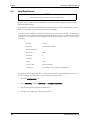
Table 2: J2 RS-232C Connector Pinout
290-000126/Rev A/Nov 03
Pin
Connection
2
RS-232C Serial Data Out
3
RS-232C Serial Data In
5
Data Ground
9
Remote +12 V
17
Cabling
6.5
Watchman 3100 User Manual
Serial Data Protocol
NOTICE
Before starting PC programming, press CAPS LOCK.
Serial RS-232C communication is established via Optech’s optional keypad. Optech recommends using this keypad.
All programming software is embedded and available as soon as serial communication is established. Programming screens are shown on the range display.
If you want to store readings or do not have a keypad, you can use a PC instead. The Watchman
3100 interfaces easily with any PC terminal communications program. To establish a serial data
connection, your computer must be equipped with an RS-232C (or RS-422) port. Use the following settings:
RS-422
Tx only
RS-232C
Tx Rx (bi-directional)
ASCII characters
Baud rate
9600
Data bits
8
Stop bits
1
Parity
None
Flow control
None (Xon/Xoff)
Serial port
According to your computer configuration.
For Windows 98™ or Windows NT™, use the HyperTerminal program with the below steps. If
your PC is equipped with Windows 3.1™ software, follow these steps:
1. Select the ACCESSORIES icon.
2. Select TERMINAL, and then SETTINGS and COMMUNICATIONS.
3. Set communications parameters as listed above.
4. Save the correct settings to a file for quick recall.
18
290-000126/Rev A/Nov 03
Watchman 3100 User Manual
7
Mounting
MOUNTING
IMPORTANT
For installation drawings and information, see Chapter 8.
7.1
Mounting Elements
The Watchman 3100 enclosure provides a variety of mounting options to suit specific applications and installations. The enclosure and the interface module are water-proof and dust-proof, as
long as the module is properly installed on the enclosure and all O-rings and seals are properly
installed and in good condition.
7.1.1
Mounting Bosses
The aluminum mounting bosses on the sides of the enclosure have two external, threaded, mounting holes:
7.1.2
M8
For standard installation using an M8 x 1.25 socket head
cap screw.
1/4” NPT
For auxiliary mounting: for example, with heavy vibration,
as a purging port, or as a cooling port.
Mounting Holes
For surface mounting or for extra rigidity, four threaded M8 x 1.25 holes are provided on the base
of the enclosure in a 110 x 240 mm pattern.
7.1.3
Orientation of the Interface Module
The interface module is usually oriented so that the cable conduits are at the bottom of the
module, shielded from weather and dust. To accommodate your installation, the module can be
rotated 180° so that cabling emerges from the top. Note that in this case the D37 connector on
the base of the module must also be rotated 180° to maintain its mating connection on the enclosure.
290-000126/Rev A/Nov 03
19
Mounting
Watchman 3100 User Manual
7.2
Mounting Configurations
7.2.1
Surface Mounting and Alignment
7.3
♦
Ensure that the support is sufficiently rigid to prevent misalignment.
♦
Before drilling through holes into the support, consider any future alignment problems or
equipment that may obstruct the rangefinder beam.
♦
The degree of alignment depends upon the size of the mounting holes. To facilitate alignment, Optech recommends oversized holes with suitable clearance.
♦
To ensure the correct vertical alignment, use shims or washers.
♦
For information on Optech’s optional articulating bracket and surface-mount installation, see
"Appendix: Product Information"‚ page 67.
Other Mounting Configurations
For assistance with other mounting options, please contact Optech or your Optech representative.
See also "Appendix: Product Information"‚ page 67, for information on product options that may
apply to your installation.
20
290-000126/Rev A/Nov 03
Watchman 3100 User Manual
Installation
8
INSTALLATION
8.1
Installation Procedure
CAUTION
Visible and Invisible Laser Light - Do Not Stare into Beam
Before closing the interface module, program the laser pointer to OFF.
Watchman 3100 may fire as soon as power is supplied.
NOTICE
Do not point the Watchman 3100 at the sun.
Strong sunlight reflections can cause erratic range readings.
This procedure assumes that you are already familiar with the cabling and mounting information
in Chapters 6 and 7. For installation drawings, see page 23. For information on installing product
options, see "Appendix: Product Information"‚ page 67.
Install
1. Locate a suitable installation site ("Mounting"‚ page 19).
2. Install the unit, but do not secure it in place until final alignment is complete:
For
Use
Standard installation
M8 x 1.25 cap screws on mounting bosses
Extra rigidity/security
1/4” NPT mounting on mounting bosses
Surface mounting
M8 x 1.25 screws into enclosure base.
3. If you rotate the interface module to facilitate the cable routing or entry location, remember to
rotate the D37 connector on its base as well, to maintain the mating connection with the
enclosure. Optech recommends that, wherever possible, the conduit entry face down.
Cable and Power
1. Open the interface module.
2. Detach the module from the enclosure to simplify the task of cabling, if necessary.
290-000126/Rev A/Nov 03
21
Installation
Watchman 3100 User Manual
Save the five O-rings (on each mounting screw and the lid/module seal).
3. Run your power and data cables through the cable conduits.
NOTICE
Unit is fully sealed at factory. Failure to maintain sealed entry will void warranty.
4. Make all connections to J3, the terminal block on the interface board.
To simplify the task of routing the wires, remove the mating connector on the terminal block,
and re-install it when this step is complete. The unit operates off 24 VDC or 120 VAC
(option). For J3 terminal assignments, see page 16, or Figure 8, page 25.
5. For local RS-232C test and programming, plug in the optional keypad or remote device to J2,
the 9-pin serial port.
To use a remote device other than Optech’s keypad or a laptop computer, see "Signal and
Data Isolation"‚ page 16, and "Serial Data Protocol"‚ page 18. The device must be unplugged
before the interface module can be closed.
6. Re-install the interface module on the enclosure:
a)
Check the five O-rings.
b) Align the mating connectors.
c)
Plug in the module.
d) Install the M4 mounting hardware on the lid, but do not replace the lid at this point.
7. Power ON (page 34).
If the unit is too hot or too cold, the unit may not turn on immediately ("Thermal Protection"‚
page 36).
NOTICE
At cold temperatures, unit may take up to 45 minutes to turn on. Range readings may
then fluctuate for first 15 minutes. Accuracy gradually improves as unit warms up.
Align and Program
1. Program the laser pointer ON (page 42). Confirm that the red POINTER ON LED on the
interface board is illuminated.
.
CAUTION
Visible Laser Light - Do Not Stare into Beam
Do not use binoculars or devices that collect light to locate pointer beam.
22
290-000126/Rev A/Nov 03
Watchman 3100 User Manual
Installation
2. Locate the red pointer beam spot. The pointer beam is co-aligned with the rangefinder beam.
3. Align the unit (Chapter 9).
Use shims or washers to adjust the unit’s position until the unit is correctly aimed.
4. Program the laser pointer OFF. Confirm that the red POINTER ON LED on the interface
board is now off.
5. Program the unit for plant operation (Chapter 1111). The unit is now ready for 4-20 mA
analog output calibration, if desired.
Final Steps (After Alignment)
1. Unplug the RS-232C data cable.
2. Replace the lid of the interface module.
3. Tighten all mounting hardware.
4. Begin operation.
8.2
Installation Drawings
Figure 4: Unit Top View (205-000106)
290-000126/Rev A/Nov 03
23
Installation
Watchman 3100 User Manual
Figure 5: Unit Cross-Section (205-000106)
Figure 6: Unit Bottom View (205-000106)
24
290-000126/Rev A/Nov 03
Watchman 3100 User Manual
Installation
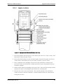
Figure 7: Unit Front View (205-000106)
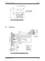
8.3
Field Interface
Figure 8: Field Interface Board Schematic (230-010073)
290-000126/Rev A/Nov 03
25
Installation
26
Watchman 3100 User Manual
290-000126/Rev A/Nov 03
Watchman 3100 User Manual
9
Alignment Procedures
ALIGNMENT PROCEDURES
This section describes three methods of aligning the Watchman 3100:
Laser pointer method
IF
Laser pointer spot is visible on the target
AND No one is within the field of view of the laser pointer or
able to look directly into the laser pointer beam.
Distance method
IF
Exact range to the target is known
AND Laser pointer method cannot be used.
Retro-reflector method
IF
Range to the target is >250 m
AND Environment is dusty or there is bright sunlight.
As a rule, use the laser pointer method wherever possible.
After alignment, the Watchman 3100 is ready to be operated and programmed as discussed in
Chapters 10 and 1111.
290-000126/Rev A/Nov 03
27
Alignment Procedures
9.1
Watchman 3100 User Manual
Laser Pointer Method
DANGER
Visible Laser Light - Do Not Stare Into Beam
Use of controls or adjustments or performance of procedures other than those specified
herein may result in hazardous exposure to laser light. See also "Visible and Infrared
Laser"‚ page 7.
Do not use binoculars or devices that collect light.
NOTICE
Rangefinder Damage
Do not point unit at sun.
The laser pointer produces a visible laser beam that is aligned at the factory to be collinear with
the rangefinder beam. It projects a red spot that marks the location of the rangefinder beam.
The laser pointer is most effective when ambient light is low and the red spot is clearly visible.
When ambient light is high, as in bright sunlight, the eye's ability to see the spot is reduced. In
this case, use the distance or retro-reflector method.
1. Check that:
♦
♦
♦
No-one is within the field of view of the laser pointer or able to look directly into the
laser pointer beam.
No-one is holding a target for the beam.
The unit is not installed at eye level.
2. Power the unit ON.
3. Program the laser pointer ON. (The pointer defaults to OFF upon power-up.)
4. Locate the laser pointer beam spot. This spot can be difficult to see if the area is well-lit.
5. Adjust the position of the unit until the beam spot is centred on the desired location.
6. As an eyesafety precaution, program the laser pointer OFF.
28
290-000126/Rev A/Nov 03
Watchman 3100 User Manual
9.2
Alignment Procedures
Distance Method
DANGER
Visible Laser Light - Do Not Stare Into Beam
Use of controls or adjustments or performance of procedures other than those specified
herein may result in hazardous exposure to laser light. See also "Visible and Infrared
Laser"‚ page 7.
IMPORTANT
To use this method, exact range(s) to target must be known.
The distance method verifies that the rangefinder is hitting a target and producing the expected
analog range reading. To use this method, therefore, you must know the exact distance(s) to
which the rangefinder will be firing: for example, along a tripper car path.
The target must be mobile. One person is required to monitor the range readings, and a second
person may be used to move the target.
1. Position the Watchman 3100 directly in line with the target.
2. Position the target. If the target is expected to move in operation (for example, a tripper car),
move it to one end of its path as close as possible to the Watchman 3100.
3. Power the unit ON.
4. As an eyesafety precaution, check that the laser pointer is programmed OFF. (The pointer
defaults to OFF upon power-up.)
5. Record the analog signal output (range) from the Watchman 3100.
6. If the target is expected to move in operation, move it to the extreme end of its path as far
away as possible from the unit.
7. Record the analog signal output (range) again.
8. Confirm that the analog outputs match the expected range readings:
YES
The unit is properly aligned and can be locked into position.
NO
Go to Step 9.
9. Adjust the position of the unit or the target by adding washers or by other methods.
10. Repeat Steps 5-9 as required until the analog signal outputs match the expected range
readings.
290-000126/Rev A/Nov 03
29
Alignment Procedures
9.3
Watchman 3100 User Manual
Retro-Reflector Method
DANGER
Visible Laser Light - Do Not Stare Into Beam
Use of controls or adjustments or performance of procedures other than those specified
herein may result in hazardous exposure to laser light. See also "Visible and Infrared
Laser"‚ page 7.
Do not use binoculars or devices that collect light
NOTICE
Rangefinder can be damaged by excessively strong signal returns. At ranges of less than
30 m, use retro-reflectors ONLY IF environment is consistently very dusty.
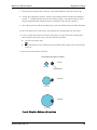
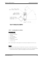
This method is ideal for verifying that the rangefinder is hitting the target in dusty environments at
ranges of more than 100 m, or in clear environments at ranges of more than 1 km. It requires
retro-reflectors such as 3M reflective tape or bicycle reflectors fixed on a mobile target. One
person is required to monitor the range readings while another moves the target.
This method relies on receiving a strong reflection that saturates the rangefinder receiver,
producing a SATURATION error code over the serial output. It is not intended to monitor the
exact range to the target, since saturated range readings may not meet typical accuracy specifications.
1. Attach retro-reflectors to the target.
2. Position the target at least 50 m from the unit.
3. Position the Watchman 3100 directly in line with the target.
4. To monitor the serial range output, cable the unit to the Optech keypad or a similar device.
5. Check that:
♦
♦
♦
No-one is within the field of view of the laser pointer or able to look directly into the
laser pointer beam.
No-one is holding a target for the beam.
The unit is not installed at eye level.
6. Power the unit ON.
30
290-000126/Rev A/Nov 03
Watchman 3100 User Manual
Alignment Procedures
7. Program the laser pointer ON, if desired. (The pointer defaults to OFF upon power-up.)
8. Aim the unit, adjusting its position until the range reading saturates and the SATURATION
symbol ^ is displayed to the left of the serial range reading. This indicates that the unit is
properly aligned and the rangefinder beam is striking the retro-reflectors squarely.
9. Move the target to the furthest operating range, and verify that the beam still strikes the target.
10. Move the target closer to the unit by selected intervals, repeating Step 9 at each point.
11. If you are using retro-reflectors at ranges of less than 30 m, first reduce the strength of the
return signal to protect the unit by one of the following methods:
♦
♦
Cover the laser beam spot
OR
Move the target off-axis so that the beam spot strikes only the edges of the retro-reflectors
(Figure 9).
12. Remove the retro-reflectors if desired.
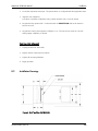
Laser Beam Spot Size on Object
At 5 m
8 cm dia.
Retro-Reflector
At 20 m
15 cm dia.
At 40 m
25 cm dia.
Figure 9: Using Retro-Reflectors with Laser Beam
290-000126/Rev A/Nov 03
31
Alignment Procedures
32
Watchman 3100 User Manual
290-000126/Rev A/Nov 03
Watchman 3100 User Manual
Operation
10 OPERATION
The Watchman 3100 can be programmed and controlled remotely from Optech’s hand-held
keypad or from any device communicating via RS-232C and using ASCII characters. Programming is discussed on page 39.
Factory settings or the most recent programmed settings are saved and restored whenever the unit
is powered ON again.
10.1
Operating Steps
1. Before powering the unit, check that:
♦ Interface cables are firmly attached at both ends and will not come loose.
♦ If using a PC, it is properly configured for remote programming, and CAPS LOCK is on
("Serial Data Protocol"‚ page 18).
2. Power ON.
The software version is briefly displayed on your keypad or PC. In continuous mode, the
Watchman 3100 begins to report range readings within seconds. In external trigger mode,
the unit reports readings only when triggered ("External Trigger"‚ page 17).
NOTICE
At cold temperatures, unit may take up to 45 minutes to turn on.
Range readings may fluctuate for the first 15 minutes. Accuracy gradually improves
as the unit warms up.
Review and follow the laser safety precautions in "Visible and Infrared Laser"‚ page 7.
3. Program other aspects of the Watchman 3100 as outlined in Chapter 11, Programming, on
page 39. Review also the operating notes in this chapter.
Programming software is embedded; no separate software installation is necessary.
4. In external trigger mode, trigger range readings as desired ("External Trigger"‚ page 17).
5. Monitor range readings, and change programmable settings as desired.
290-000126/Rev A/Nov 03
33
Operation
10.2
Watchman 3100 User Manual
Powering ON/OFF
The Watchman 3100 has no power ON/OFF switch. It is turned ON/OFF by the external power
source.
Note that the laser pointer fires continuously if it is programmed ON.
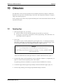
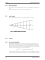
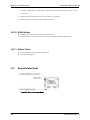
10.3
Laser Footprint
Figure 10 illustrates the dimensions of the laser beam footprint at various ranges.
Figure 10: Footprint of Rangefinder Laser Beam
10.4
Accuracy
10.4.1
Accuracy and Repeatability
The Watchman 3100 averages a number of laser shots to produce each range reading. The
number of shots averaged affects the accuracy of a reading: the higher the number of shots, the
higher the accuracy of the resulting reading. Since the Watchman 3100 fires a fixed number of
shots per second, the measurement update rate (rate of readings) determines the number of shots
that can be averaged, and thus the accuracy of the range reading:
Accuracy
↑
As Measurement Update Rate
↓
You can program the desired accuracy. Table lists the accuracy and repeatability of Watchman
3100 range readings at selected measurement update rates. The column headings are defined as:
34
290-000126/Rev A/Nov 03
Watchman 3100 User Manual
Operation
Absolute accuracy
Absolute accuracy over the full range of operating temperatures and material reflectives, and at any distance, with 1 sigma
standard deviation.
Operating accuracy
Accuracy within limited variations in temperature, material
reflectivity and distance associated with many typical installations.
Repeatability
Under steady state conditions, with 1 sigma standard deviation.
Table 3: Accuracy and Repeatability at Selected Measurement Update Rates
10.4.2
Measurement Rate
Absolute Accuracy
Within (mm)
Operating Accuracy
Within (mm)
Repeatability Within
(mm)
1 reading per 5 sec
20
5
3
1 reading per 1 sec
20
5
3
2 readings per 1 sec
25
7
4
5 readings per 1 sec
30
10
6
10 readings per 1 sec
40
15
9
20 readings per 1 sec
80
60
35
Accuracy Restrictions
At short range, a very strong return from a highly reflective target such as reflective tape will saturate the Watchman 3100’s range detector, and may produce a range reading with a degraded
accuracy. In this case a SATURATION or SAT/DROPOUT error code will be output with the
range (Table 8, page 57).
A highly reflective target at less than 10 m may produce a saturated range reading indicating that
the target is closer than it really is.
10.4.3
Low-Temperature Start
If the Watchman 3100 is cold when it is first powered ON, it may begin firing before all its components have fully warmed up. In this case initial range readings may fluctuate. Range accuracy
will gradually improve as the unit’s internal temperature stabilizes, which takes about 15 minutes.
290-000126/Rev A/Nov 03
35
Operation
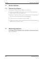
10.5
Watchman 3100 User Manual
Thermal Protection
The Watchman 3100’s thermal protection is summarized in Figure 11 below.
Figure 11: Thermal Protection
10.5.1
High-Temperature Rangefinder Protection
To protect the Watchman 3100 from temperature extremes outside its specified operating range,
the unit’s power supply is automatically shut off without warning if the temperature of the
rangefinder inside the enclosure:
Rises above 67°C
±3°C.
The power supply is re-enabled automatically and without warning when the temperature returns
to an operable level. The unit then resumes operation with the same programmed settings as
before shutdown, and begins reporting range readings again. (The laser pointer defaults to OFF.)
36
290-000126/Rev A/Nov 03
Watchman 3100 User Manual
10.5.2
Operation
High-Temperature Laser Pointer Protection
To protect the laser pointer from temperature extremes above its specified operating range, the
laser pointer is shut down automatically when the ambient temperature exceeds about 40°C. The
pointer is automatically re-enabled when the temperature drops.
10.5.3
Rangefinder DC Heater
At internal temperatures below 0°C, the Watchman 3100 rangefinder does not fire or output data.
When the unit is powered on at such a cold temperature, a heater incorporated into the
rangefinder turns on automatically to warm the unit to an operable level.
At very cold temperatures, it may take up to 45 minutes before the rangefinder is ready to fire. If
your unit includes an AC heater, the warm-up time will be shorter.
The rangefinder begins firing when its internal temperature reaches 5°C, and the heater turns off
at 8°C. Under most conditions, the rangefinder temperature will remain above 5°C from that
point on. Should the temperature drop, the heater will turn on again.
10.5.4
120 VAC Enclosure Heater (Option)
For operation in very cold environments where 120 VAC is available, Optech offers an enclosure
heater as an option.
If the temperature of the rangefinder inside the enclosure is below 0°C when the Watchman 3100
is powered ON, the rangefinder will not turn on until the heater has warmed the rangefinder to an
operable level (about 0-10° C). This may take up to 30 minutes, depending on the ambient temperature, after which the rangefinder will be warm enough to turn on. Thereafter the heater’s
thermostat will operate the heater up to a temperature of 20-25° C, at which point it will shut off.
The thermal cutoffs of the rangefinder and the heater thermostat set point are overlapped, to
ensure that the rangefinder stays ON once it reaches operating temperature.
290-000126/Rev A/Nov 03
37
Operation
38
Watchman 3100 User Manual
290-000126/Rev A/Nov 03
Watchman 3100 User Manual
Programming
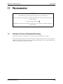
11 PROGRAMMING
IMPORTANT
Use the RS-232C port to program via keypad or PC with serial link.
Most recent programmed settings are restored when the unit is powered ON (laser pointer
defaults to OFF).
To begin programming, press M.
Rangefinder laser does not fire during programming. Laser pointer continues to fire if programmed ON.
11.1
Summary of Screens and Programmable Settings
Programming software is embedded; no separate software installation is necessary.
On the following two pages are shown the hierarchy of programming screens for the Watchman
3100 and a summary of settings that can be programmed via these screens. More detailed information is provided in the rest of this chapter.
290-000126/Rev A/Nov 03
39
Programming
Watchman 3100 User Manual
Figure 12: Watchman Programming Screens
40
290-000126/Rev A/Nov 03
Watchman 3100 User Manual
Programming
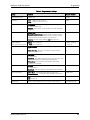
Table 4: Programmable Settings
Setting
Options
Factory Default
Measurement Units
Meters, feet
Meters
Resolution
Low: 0.00 m (1 cm) or 0.1 ft
High: 0.000 m (1 mm) or 0.01 ft
High
Trigger
Continuous: Unit internally triggered to output range readings
at selected update rate.
External: Unit outputs a range reading only when externally
triggered.
Continuous
Data Output
Range Only: Outputs range readings only.
Range/Dropout/Intensity: Outputs range readings as well as
the number of laser shots that do not return to unit, and the
relative intensity of return signals, from 0 to 6375.
Velocity: Outputs range readings and target velocity.
Range Only
Analog Settings
(Zero, span, inverse span)
20 mA: 0 to 50,000 cm
4 mA: 0 to 50,000 cm
20 mA: 3000 cm
4 mA: 0
Filter
Filter Distance: Range window for valid readings
(0-325
m).
Filter Time-Out: Number of readings for which window
distance is valid (0-127).
0
First/Last Pulse Mode
First Pulse: Use with a clear and unobstructed view of the
target/material.
Last Pulse: Use with interference such as fog, rain, dust, snow
or objects between the unit and the target/material.
Filtered Last: Use with heavy interference when lower
accuracy is acceptable.
Last Pulse
Zero Offset
Forward: Shift zero reference point for range readings closer to
target/material.
Backward: Shift zero reference point behind the rangefinder.
0
Power-Up Display
Main Menu: Unit display main menu on power-up.
Process Variable: Unit display range readings on power-up.
Main Menu
Laser Pointer
On: Pointer on (alignment only).
Off: Pointer off.
Off
Update Rate
From 1 range reading every 5 seconds to 20 per second.
1 reading/second
290-000126/Rev A/Nov 03
0
0
41
Programming
11.1.1
Watchman 3100 User Manual
Hand-Held Keypad
To facilitate test and setup in an operational environment, Optech offers an optional hand-held
keypad. The keypad uses RS-232C communication and plugs into J2 on the interface board. It
can be connected or disconnected at any time while the unit is powered ON.
11.1.2
Using the Programming Screens
When programming on PC, first ensure that CAPS LOCK is on. The programming screens are formatted for Optech’s keypad, and do not look the same when displayed on a PC. The table below
describes some of the most common screen operations.
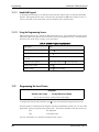
Table 5: Common Programming Operations
11.2
Operation
Step
Begin programming
Press M
Exit most screens
Press E
Backspace over an entry
(keypad)
Hold down SHIFT and press BACKSP
Choose screen option
Press letter, then press E to save and exit
Continuous update
Press C
Trigger mode
Press S to get a reading
Programming the Laser Pointer
CAUTION
Visible Laser Light
-
Do Not Stare Into Beam
Do not use binoculars or devices that collect light.
To program the laser pointer ON/OFF, press P at any time outside the programming screens.
The laser pointer is intended to help align the unit during installation and test only. For any other
application, always program the laser pointer OFF. The pointer defaults to OFF upon power-up:
ON
For alignment
OFF
At all other times.
For more information, see "Visible and Infrared Laser"‚ page 7.
42
290-000126/Rev A/Nov 03
Watchman 3100 User Manual
11.3
Programming
Main Menu Screen
When you press M to begin programming, the following screen appears.
MAIN MENU
A FORMAT C MODES
B ANALOG D SET-UP
Press E to exit
To select a menu option
Press A-D
To return to the range display Press E
The rangefinder laser does not fire during programming, but the laser pointer continues to fire if it
is programmed ON.
11.4
Format Screens
FORMAT
A UNITS
C RES
B POWER-UP D DATA
Press E to exit
11.4.1
Measurement Units for Range Readings
MEASUREMENT UNITS
A METERS
B FEET
Press E to exit
Select whether you wish the unit to measure range in meters or feet.
290-000126/Rev A/Nov 03
43
Programming
11.4.2
Watchman 3100 User Manual
Power Menu
UPON POWER-UP SHOW
A MAIN MENU
B PROCESS VARIABLE
Press E to exit
Select whether you wish to see the main menu or the process variable when the unit is powered
up.
11.4.3
Range Resolution
RESOLUTION
A LOW
B HIGH
Press E to exit
44
Resolution:
Example:
A LOW
0.00 m (1 cm) or 0.1 ft
7.54 m, 24.1 ft
B HIGH
0.000 m (1 mm) or 0.01 ft
7.545 m, 24.17 ft
290-000126/Rev A/Nov 03
Watchman 3100 User Manual
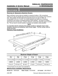
11.4.4
Programming
Data
DATA
A RANGE ONLY
B RANGE/DROPOUT/INT
C RANGE & VELOCITY
Press E to exit
A RANGE ONLY
Only range readings are displayed, in the selected measurement units.
B RANGE/DROPOUT/INT
In addition to range readings, two other useful diagnostic values are displayed. The
number of dropouts (laser shots that do not return to the unit) per range reading is a
function of the selected update rate: at a high update rate, fewer shots are averaged per
reading.
The intensity of the reflection is shown as a value from 0-6375.
C RANGE & VELOCITY
In continuous mode, outputs range as well as the velocity of the target as follows:
Velocity = (Previous range reading - Current range reading) / Update rate
Velocity is an absolute value: no positive or negative value is assigned.
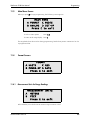
11.5
ANALOG Screens: 4-20 mA Analog Range Settings
ANALOG
A 4 mA
B 20 mA
Press
SETTINGS
C NO RANGE
D SATURATE
E to exit
4 mA Limit is:
0 cm
Press A to change
Press E to exit
290-000126/Rev A/Nov 03
45
Programming
Watchman 3100 User Manual
20 mA Limit is:
3000 cm
Press A to change
Press E to exit
These screens set the ranges corresponding to the 4 mA and 20 mA analog limits. Ranges can be
set for zero, span, and inverse span, and are displayed in the current units of measurement (centimeters or inches). The maximum value for either limit is 500,000 cm (196,850 inches).
Note that the value of the analog limit is exact if centimeters are used, but round-off errors reduce
the accuracy using feet to under one inch.
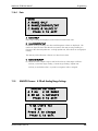
When you press A to change the limit, the following prompt appears:
INPUT A NUMBER FOR THE SETTING
Type a value and press ENTER. Press E to save the value, and check that it is now displayed.
NO RANGE ALARM
A 4 mA
C IGNORE
B 20 mA
Allows the user to program an analog output response to a "no range" reading, such as no signal
return.
SATURATE ALARM
A 4 mA
C IGNORE
B 20 mA
Allows the user to program an analog output response to a "saturated" reading, such as too strong
a signal.
46
290-000126/Rev A/Nov 03
Watchman 3100 User Manual
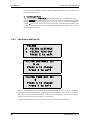
11.6
Programming
Modes Screens
MODES
A OUTPUT MODE C FILTER
B PULSE
D TRIGGER
Press E to exit
OUTPUT MODE
A DIRECT
B EXTRA AVERAGING
Press E to exit
A DIRECT
Outputs the range reading directly.
B EXTRA AVERAGING
Outputs a rolling average of the last five readings.
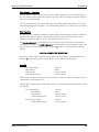
11.6.1
First/Last-Pulse Range Filter
PULSE
A FIRST PULSE
B LAST PULSE
C FILTERED LAST PULSE
Press E to exit
A FIRST PULSE
This mode is best if there is a clear and unobstructed view of the target/material, with no
fog, steam, rain, snow, dust or other possible targets in the way. Range readings are
made to the first object encountered.
B LAST PULSE
This mode improves ranging through fog, steam, rain, snow or certain quantities of dust.
It can provide the correct range even if stationary objects partly block the unit’s line of
sight, as long as the objects are separated by more than 3 m (10 feet) and part of the laser
290-000126/Rev A/Nov 03
47
Programming
Watchman 3100 User Manual
beam travels beyond them. Range readings are made to the last object encountered, filtering out earlier returns.
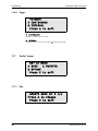
C FILTERED LAST PULSE
This mode is similar to LAST PULSE, but the rangefinder is now optimized to range
through very thick fog, steam, rain, snow or dust. This mode provides usable and stable
ranges at the cost of possible lower accuracy (±0.5 to 8 cm). The PARTIAL DROPOUT
symbol < may appear ahead of the serial range output. Note that the unit relies on line
of sight; laser light must be able to reach the target/material and return to the unit for a
measurement to be made.
11.6.2
Filter Distance and Time-Out
FILTER
A FILTER DISTANCE
B FILTER TIME-OUT
Press E to exit
FILTER DISTANCE IS:
0 cm
Press A to change
Press E to exit
FILTER TIME-OUT IS:
0
Press A to change
Press E to exit
These screens provide a sliding window filter for both the analog and serial output. The Watchman 3100 assumes that the longest readings are valid, and therefore uses a one-way window to
ignore short readings outside the window. This screens out interference and obstacles passing
between the unit and the target/material it is monitoring.
A valid reading within the window resets the reference for the next measurement.
48
290-000126/Rev A/Nov 03
Watchman 3100 User Manual
Programming
Filter Distance - One-Way
The filter distance determines how much shorter a valid reading can be from the previous reading. Any shorter reading outside the window is ignored, while all readings longer than the previous one are considered valid.
The unit re-transmits the last valid measurement until another valid measurement occurs or the
programmable filter time-out expires. The maximum filter distance is 32,500 cm (12,795 inches).
Filter Time-Out
The filter time-out, measured in number of range readings, determines the number of readings for
which the filter distance applies. After the time-out expires, the next measurement is valid
whether it is within this distance or not. The maximum time-out is 127.
The FILTER DISTANCE screen displays the current value in the current units of measurement
(centimeters or inches); the FILTER TIME-OUT screen displays the current number of range readings selected for the filter distance. When you press A in either screen, the following prompt
appears:
INPUT A NUMBER FOR THE SETTING
Enter the new value, which will be shown at bottom left of the display. Press ENTER to save it,
and then E to return to the screen. Check that the correct value is now displayed.
Examples
First range reading
Filter distance
Filter time-out
Valid reading must be
3,500 cm
200 cm
5 range readings
3,300 or greater
If there are no valid measurements, the signal remains at 3,500 cm. After five readings, the next
range reading is valid whatever it is.
The Watchman 3100 provides a sliding filter: that is, a valid reading resets the filter for the following readings:
First range reading
Filter distance
Filter time-out
Valid reading must be
3,500 cm
200 cm
5 range readings
3,300 or greater
Second range reading
Valid reading must be
3,400 cm
3,200 or greater.
290-000126/Rev A/Nov 03
49
Programming
11.6.3
Watchman 3100 User Manual
Trigger
TRIGGER
A CONTINUOUS
B EXTERNAL
Press E to exit
A CONTINUOUS
Updates automatically at set rate.
B EXTERNAL
Updates when TTL pulse received or S pushed on keypad.
11.7
Set-Up Screens
SET-UP MENU
A RATE
C POINTER
B OFFSET
Press E to exit
11.7.1
Rate
UPDATE RATE AT 1 r/s
Press A to change
Press E to exit
50
290-000126/Rev A/Nov 03
Watchman 3100 User Manual
Programming
UPDATE RATE:
A 1-20 readings/sec
B 1-5, 10, 20, 60 sec/r
Press E to exit
The measurement update rate is a function of the number of shots that are averaged, and is therefore related to the unit’s accuracy and repeatability:
Fastest, least accurate, rate
Slowest, most accurate, rate
20 readings/second
5 seconds per reading.
When you press A, the following prompt appears:
INPUT A NUMBER FOR THE SETTING
Enter the new value, which will be shown at bottom left of the display. Press ENTER to save it,
and then E to return to the screen. Check that the correct value is now displayed.
Note that when the update rate is 19 readings per second, the actual rate will be 1 shot per reading. This feature is implemented for diagnostic purposes when single shots per reading need to be
observed. Accuracy will be lower than for 20 readings per second.
For more information, see "Accuracy and Repeatability"‚ page 34.
11.7.2
Offset
OFFSET+ XXX mm
Press E to exit
DIRECTION TO SHIFT
ZERO POINT FORWARD
A FORWARD
B BACKWARD
Press E to exit
Allows the user to set the zero reference for the range readings:
290-000126/Rev A/Nov 03
51
Programming
Watchman 3100 User Manual
A FORWARD
Set the zero reference point in front of the rangefinder.
B BACKWARD
Set the zero reference point behind the rangefinder.
11.7.3
Pointer
POINTER
A ON
B OFF
Press E to exit
Turn the visible laser pointer on or off.
52
290-000126/Rev A/Nov 03
Watchman 3100 User Manual
Maintenance
12 MAINTENANCE
12.1
Enclosure Window Cleaning and Maintenance
NOTICE
Window is delicate.
Do not use abrasive cleaners, squeegees or other cleaning implements that may mar or
gouge the window coating.
1. Wash the window with a mild solution of soap and lukewarm water.
2. Using a soft cloth or sponge, gently wash the glass to loosen dirt and grime.
3. Rinse well with clean water.
4. To prevent spotting, thoroughly dry with a chamois or cellulose sponge.
12.1.1
Compatible Cleaning Agents
Aqueous Solutions of Soaps or Detergents
♦
♦
♦
♦
♦
♦
Windex
Joy
Fantastik
Top Job
Mr. Clean
Formula 409
Organic Solvents
♦
♦
♦
♦
♦
♦
Butyl Cellosolve
Kerosene
Naphtha (VM&P) grade
Hexcel, F.O. 554
Neleco-Placer
Turco 5042
290-000126/Rev A/Nov 03
53
Maintenance
Watchman 3100 User Manual
Alcohols
♦
♦
Methanol
Isopropyl alcohol
Note: Remove all residual organic solvents with a secondary rinse.
12.1.2
Graffiti Removal
♦
♦
12.2
Butyl Cellosolve for removal of paints, marking pen, lipstick, etc. Masking tape, adhesive
tape and lint removal tools work well for lifting off old weathered paints.
Kerosene or VM&P Naphtha for removal of labels, stickers, etc. If these solvents will not
penetrate sticker material, apply heat (hair dryer) to soften the adhesive.
Enclosure O-Rings and Seals
The interface module is water-proof and dust-proof as long as all seals are installed and in good
condition. When servicing the unit, check the module O-rings listed below:
Module
Enclosure
1
Lid/module seal
2
Each cable conduit
1
Lid/enclosure seal
1
Around D37 connector on enclosure lid
2
Rangefinder transmit and receive windows
1
Laser pointer window
4
Mounting screws attaching module to enclosure
6
Two mounting holes on each mounting boss.
For O-ring kits, contact Optech.
54
290-000126/Rev A/Nov 03
Watchman 3100 User Manual
12.3
Maintenance
Fuses
There are three replaceable glass fuses (F1, F2, F3) on the interface board, as listed in the table
below. Fuses are installed at the factory for the options ordered. Fuses are protected by reusable
fuse covers.
The fuses F2 and F3 are laid out so that they cannot be installed together.
For
10.5-30 VDC operation (standard)
Install
120 VAC operation (120 VAC option)
F1 and F2
F3.
Table 6: Replaceable Fuses
Fuse
Rating
Function
F1
2A
10.5-30 VDC power input (fast-blow)
(24 VDC nominal)
F2
3A
24 VDC rangefinder heater
F3
2A
120 VAC line fuse
--
2A
Internal rangefinder fuse (slow-blow)
The rangefinder is protected by a fourth fuse, located on the back of the rangefinder connector
panel. Since F1 is a fast-blow fuse, it will blow first. The rangefinder fuse can be replaced if
necessary by opening the enclosure and the rangefinder (see "Servicing the Enclosure", page 63).
12.4
Storage
Store the Watchman 3100 in a clean, dry environment at temperatures between -20° C and +70°
C.
12.5
Returning the Watchman 3100 to the Factory
Before returning the unit, note the serial number on the label and contact Optech or your Optech
representative. If the problem cannot be resolved by telephone, fax or e-mail, Optech will issue a
Return Authorization Number.
Do not ship a unit to Optech without a Return Authorization Number.
290-000126/Rev A/Nov 03
55
Maintenance
Watchman 3100 User Manual
If the repair is covered by warranty, Optech will notify you and repair the unit promptly. If the
repair is deemed chargeable, Optech will quote the estimated repair costs and proceed promptly
upon your approval.
56
290-000126/Rev A/Nov 03
Watchman 3100 User Manual
Troubleshooting
13 TROUBLESHOOTING
The following table outlines the troubleshooting information in this chapter.
Table 7: Troubleshooting Summary
Problem
Action
No operation
(Section 13.3)
1. Check diagnostic LEDs.
2. Check unit temperature/Wait for unit to
warm up or cool down.
Intermittent operation
(Section 13.4)
1.
2.
3.
4.
Erratic/fluctuating/short readings
(Section 13.5)
1. Try filtered last-pulse mode.
2. Wait for unit to warm up.
3. Check rangefinder lens for dust.
Check error codes.
Check unit temperature.
Check operating environment.
Check programming values.
Before contacting Optech, follow the troubleshooting procedures in the table above and then
conduct a local test (Section 13.6).
13.1
Error Codes
Table 8 below lists the error codes that can be output.
Table 8: Error Codes
Code
Description
Serial Output
Analog
Output
SATURATION
Return signal too strong (target/material highly
reflective). Measurement may not meet typical
accuracy specifications, and may be shorter than
actual,
^
N/A
PARTIAL DROPOUT
Fewer than 50% of laser shots returned to unit.
Measurement valid but may not meet typical
accuracy specifications.
<
N/A
SAT/DROPOUT
Both saturation and partial dropout. Measurement may not meet typical accuracy specifications, and may be shorter than actual,
*
N/A
OUT OF RANGE
No laser shots returned to unit. No range provided.
NO RANGE
User
selected
290-000126/Rev A/Nov 03
57
Troubleshooting
13.2
Watchman 3100 User Manual
Diagnostic LEDs
The interface board and the rangefinder panel hold the three LEDs described in Table 9 below.
Table 9: Diagnostic LEDs
Colour
Normal
Operation
Label
Function
Description
Yellow
Flashing
LED 1
DATA OUT
Data is being transmitted. Since data is
sent after each laser burst, this also indicates the laser firing rate.
Red
Off
LED 2
POINTER ON
The laser pointer is programmed ON
(default is OFF). Observe all safety precautions.
Green
On
LED 3
POWER ON
Power is being supplied to the rangefinder.
58
290-000126/Rev A/Nov 03
Watchman 3100 User Manual
13.3
Troubleshooting
No Operation
IMPORTANT
For terminal block cabling, refer to wiring guide inside lid.
1. Check all external cabling, connections and associated equipment.
2. If the POWER ON LED is off, check that:
All heating and cooling equipment is functioning. The unit’s thermal cutoff switches are
self-resetting, and the unit is disabled and re-enabled without warning ("Thermal Protection"‚ page 36).
Correct voltage is present at the correct terminals.
Fuses on the interface board are installed and functional (Table 6, page 55). The fuses
are protected by reusable fuse covers.
♦
♦
♦
3. If the unit is not communicating, check the DATA OUT LED:
Not flashing:
♦ Program the unit for continuous mode ("Range Resolution"‚ page 44), or send an ASCII
C.
♦ Check that the D9 connector is securely attached.
Flashing:
Check that the polarity of the field wiring is correct.
♦
4. For 4-20 mA analog data, check that the analog current at the terminal block is correct, and
that the 4 mA and 20 mA set points are programmed correctly ("ANALOG Screens: 4-20 mA
Analog Range Settings"‚ page 45).
290-000126/Rev A/Nov 03
59
Troubleshooting
13.4
Watchman 3100 User Manual
Intermittent Operation
In Optech’s experience, intermittent problems are usually related to the environment in which the
unit operates. For this reason the Watchman 3100 has been designed so that environmental problems can be distinguished from instrument problems with ease. The unit can also be tested
locally, to eliminate any possible interference from the line or other equipment ("Local Test"‚
page 62).
1. Check all external cabling, connections and associated equipment.
2. Check the serial output for error codes (Table 8, page 57).
3. Check that all heating and cooling equipment is functioning. The unit’s thermal cutoff
switches are self-resetting, and the unit is disabled and re-enabled without warning ("Thermal
Protection"‚ page 36).
4. If the unit is sending invalid output (PARTIAL DROPOUT, SAT/DROPOUT), check that:
♦
♦
♦
♦
No dust, smoke, steam, rain or other environmental condition is interfering with a clear
line of sight between the unit and the target/material.
All windows and the sightglass (if provided) are clean.
The air curtain or spray ring is functioning properly (if provided).
The unit is programmed appropriately for its operating environment: window distance,
window time-out, analog limits, first/last-pulse mode.
5. If the analog output remains the same even when the range changes, check that the analog
zero and maximum settings correspond to valid range readings (default 0-30 m). If the range
differential is small when compared to the analog span, readings may appear not to change.
For example, if ranges vary from 40-50 m and analog settings are for 0-200 m, the analog
output may appear fixed.
60
290-000126/Rev A/Nov 03
Watchman 3100 User Manual
13.5
Troubleshooting
Erratic/Fluctuating/Short Readings
Erratic or drifting range readings may be caused by interference between the rangefinder and the
target/material, either from dust inside the rangefinder or from atmospheric interference such as
dust or rain. Such readings may also be the temporary result of a cold unit that is warm enough to
fire, but is still warming up internally.
If your unit is producing erratic readings or ranges that are much shorter than expected, there may
be a build-up of dust on the transmitter lens inside the rangefinder. Especially in first-pulse mode,
this may cause the unit to report a very short range reading (e.g., 0.05 m) to the enclosure window
rather than to the target/material being measured.
Dust on the inside of the rangefinder lens is clearly visible in good light.
1. If the unit is in last-pulse mode: reprogram the unit to filtered last-pulse mode ("First/LastPulse Range Filter"‚ page 47). This may eliminate interference from dust, rain or similar particles.
2. After a low-temperature start: wait for about 15 minutes for the unit’s internal temperature to
stabilize. Range accuracy will gradually improve over this period.
3. Power the unit OFF.
4. Open the enclosure and remove the rangefinder ("Servicing the Enclosure"‚ page 63).
5. Look into the transmitter lens (the right-hand lens) to check for dust.
6. If dust is visible, contact Optech for cleaning instructions. Do not open the rangefinder
without direct authorization from Optech.
290-000126/Rev A/Nov 03
61
Troubleshooting
13.6
Watchman 3100 User Manual
Local Test
If you have followed the steps in the previous section and the problem persists, test the unit to a
known, portable target such as a cardboard sign. Use a digital multimeter and Optech’s keypad (if
provided) to test the analog and RS-232C serial output.
1. Reposition the Watchman 3100 and range it to the portable target.
2. Note the programmed analog limits, and then reprogram them temporarily to conform to the
target range (page 45).
3. If desired, use the laser pointer to confirm that the laser beam is hitting the target. For laser
pointer safety precautions, see "Visible and Infrared Laser"‚ page 7.
CAUTION
Visible Laser Light - Do Not Stare Into Beam
Do not point or install the unit at eye level where people may be working.
4. Check the range output locally on the analog and serial lines:
RS-232C serial
Use Optech keypad or similar device.
Analog
Use digital multimeter.
5. Move the target while monitoring the unit’s output.
6. Check that the serial and analog outputs ramp up smoothly.
7. If the range readings under test are:
Consistent
The problem may be related to the operating environment.
Go to Step 8.
Inconsistent
Consult Optech.
8. Check all electrical interconnections and related equipment, and verify that there are no environmental obstacles such as dense dust and dirty windows.
9. Reprogram the unit with its original analog limits.
62
290-000126/Rev A/Nov 03
Watchman 3100 User Manual
13.7
Troubleshooting
Servicing the Enclosure
Figure 13: Rangefinder Connector Panel (Inside Enclosure)
NOTICE
Dust inside the rangefinder may cause incorrect readings. When the rangefinder is
outside its enclosure, always keep the rangefinder in a clean and dust-free environment.
13.7.1
Removing the Rangefinder from the Enclosure
1. Power the unit OFF, and disconnect all external cabling.
2. Move the Watchman 3100 to a clean environment such as a laboratory or office. Protect the
inside of the unit from dust and dirt during this step.
3. Remove the top two hex head screws from the front window assembly. Do not remove the
assembly itself, which is still attached by the bottom two screws.
4. Loosen the four captive screws on the enclosure lid. To avoid stripping the screws, do not
loosen them any more than necessary.
5. Carefully lift the lid, with interface module, off the enclosure.
6. Place the lid upside down above the enclosure, so that the internal ribbon cable is exposed.
7. On the rangefinder base plate inside the enclosure, remove the four screws, one in each
corner, that attach the base plate to the enclosure.
290-000126/Rev A/Nov 03
63
Troubleshooting
Watchman 3100 User Manual
One screw secures the transmitter baffle, a curved, black-anodized aluminum component
between the rangefinder lenses and the enclosure window, to the base plate. Remove this
baffle carefully, and note its mounting orientation.
If your unit has a heater, ensure that the heater thermostat in one corner of the plate is not
damaged while removing the screws.
8. If your unit has an AC power supply, two of the base plate screws attach the power supply to
the enclosure. Carefully remove the power supply from the enclosure.
9. Carefully lift the base plate out of the enclosure, and turn it over.
10. Remove the four 4-40 x 3/8” screws that attach the rangefinder to the base plate.
11. If necessary, disconnect the ribbon cable from the rangefinder panel.
12. If you are not going to replace the rangefinder in the enclosure immediately:
a)
Check that there is no dirt or dust on the lid and O-rings.
b) Re-install the base plate, enclosure lid and all O-rings.
c)
Check that all cables are inside the enclosure.
d) Re-install the two top screws on the window assembly.
e)
13.7.2
Put the enclosure in storage.
Installing the Rangefinder in the Enclosure
1. In a strong light, check for dust on the inside of the rangefinder transmitter lens (the right-hand
lens). If dust is visible the rangefinder may produce incorrect readings. In this case, contact
Optech for cleaning instructions.
2. Turn the rangefinder base plate over.
3. Attach the rangefinder to the base plate by installing the four 4-40 x 3/8” mounting screws.
Do not touch the rangefinder lenses.
4. Attach the transmitter baffle to the mounting screw by the rangefinder lenses. Ensure that the
baffle curves around the right-hand lens (when looking into the lenses), separating it from the
other lens.
5. Carefully lower the base plate into the enclosure.
64
290-000126/Rev A/Nov 03
Watchman 3100 User Manual
Troubleshooting
6. Connect the ribbon cable securely from the enclosure lid to J2 and J1 on the rangefinder
panel.
7. If your unit has an AC power supply:
a)
Carefully lower it into position on the base plate.
b) Connect the ribbon cable to J2 on the power supply.
8. Attach the base plate and power supply (if provided) to the enclosure by installing the four
mounting screws, one in each corner.
9. Replace the enclosure lid and tighten the four captive screws.
10. Install the top two screws on the window assembly.
11. Cable, install, align and program the unit for operation.
290-000126/Rev A/Nov 03
65
Troubleshooting
66
Watchman 3100 User Manual
290-000126/Rev A/Nov 03
Watchman 3100 User Manual
Appendix: Product Information
14 APPENDIX: PRODUCT INFORMATION
This appendix contains information on product options available from Optech.
14.1
Hand-Held Programmer Communications Configuration
For use with the Watchman 3100, Optech’s handheld programmer can be configured with a baud
rate of 9600 kbps.
To configure the handheld programmer:
1. Confirm that the keypad is powered by checking that the backlight is on or that data is displayed.
2. Simultaneously press the F1, SHIFT, and CTRL keys. Hold them down until the menu
appears on the display.
3. Release the keys.
4. Follow the instructions on the display:
a)
To change the baud rate, press F1 until the desired rate is displayed.
b) To quit the menu without saving changes, press F4. The keypad settings will default to
the original value when powered off and back on again.
c)
To save changes permanently, press F5.
290-000126/Rev A/Nov 03
67
Appendix: Product Information
14.2
Watchman 3100 User Manual
Options
Figure 14: Options for Optech Level Monitors and Object Positioners
14.2.1
Hand-Held Programmer
See manufacturer’s documentation for more information.
14.2.2
120 VAC Power Supply
See manufacturer’s documentation for more information.
14.2.3
120 VAC Heater
See manufacturer’s documentation for more information.
68
290-000126/Rev A/Nov 03
Watchman 3100 User Manual
14.2.4
PG 13.5 Conduit Entry Set
♦
♦
14.2.5
Appendix: Product Information
Replaces NPT conduit entries on field interface module
Designed for non-armored control cables
Air Curtain
Use dry, oil-free, instrument air or nitrogen.
14.2.6
Spray Ring
For flange-mount applications only. See Figure 13-2.
Figure 15: Spray Ring Flange Accessory
14.2.7
Sightglass and Gaskets
For flange-mount applications only, must be ordered together. Available in 150, 300 and 600
class, and in 4” and 6” sizes.
290-000126/Rev A/Nov 03
Flange gasket
Seals your flange to Optech sightglass.
Bezel gasket
Seals Optech unit to Optech sightglass.
69
Appendix: Product Information
14.2.8
Watchman 3100 User Manual
Sightglasses
♦
♦
Metaglass sightglass for pressure applications
LEXAN sightglass with 150 class for unpressurized applications
Figure 16: Sightglass and Retainer Flange Accessory
70
290-000126/Rev A/Nov 03
Watchman 3100 User Manual
14.2.8.1
Appendix: Product Information
Sightglass Installation
Figure 17: Sightglass and Gasket Installation (Front View)
1. Ensure the sightglass and bezel glass are clean and free from dirt or oil. If they are dirty, clean
them with a commercial glass cleaner.
2. Remove the white backing from the foam bezel gasket, and attach the gasket over the unit
window frame, with the thick part over each other so that the screws are visible.
3. Place components on the standpipe as shown in the above illustration, with the raised
grooved face down towards the tank, and the spray holes (if spray ring supplied) facing up
toward the sightglass.
4. Bolt the retainer flange to the standpipe using only 6 bolts. Then insert the mounting brackets
opposite each other, and hand-tighten them with the two remaining bolts.
5. Place the unit in the center of the brackets. Then insert the M8 bolts, nuts and flat/lock
washers as shown in the above illustration. Insert the M8 bolts all the way into the block,
leaving the nuts loose.
290-000126/Rev A/Nov 03
71
Appendix: Product Information
Watchman 3100 User Manual
6. Center the unit and slide the two brackets until both rest on the retainer flange. Then tighten
the brackets.
7. Push down the centered unit on the top, and then tighten the rest of the M8 nuts.
Notes:
♦ Figure 17 above covers 4" and 6" non-pressurized, class 150#, 300# and 600# flanges.
♦ In the 6", 300# and 600# application, rotate the brackets 180° around the flange bolt and bolt
them directly to the mounting block. Nuts are not necessary.
14.2.9
Articulating Bracket
For 3100/3310/3315 enclosures when they are not flange-mounted.
Figure 18: Articulating Bracket, Front View
72
290-000126/Rev A/Nov 03
Watchman 3100 User Manual
Appendix: Product Information
Figure 19: Articulating Bracket, Side View
14.2.9.1
Articulating Bracket Installation
Required Components
1
1
1
2
2
2
2
2
Articulating bracket
3/4-10 x 1 1/2” hex bolt
3/4-10 nut
3 1/4” flat washer
M8 x 18 mm hex bolts
M8 flat washers
1/4” NPT SS close nipples
1/4” NPT SS caps
Note: Caps and nipples usually shipped as one assembly, with nipples screwed on to caps.
Procedure
1. Mount the articulating bracket to a stable surface, using the 3/4-10 bolt, washers and nut.
2. Mount the unit to the articulating bracket, using the two 1/4” NPT close caps/nipples and the
two M8 bolts and washers. Tighten the caps/nipples, but leave the M8 bolts loose.
290-000126/Rev A/Nov 03
73
Appendix: Product Information
Watchman 3100 User Manual
3. Using the caps/nipples as a pivot point, adjust the vertical position of the unit with a large
screwdriver.
4. Adjust the horizontal position of the unit using the 3/4-10 bolt.
5. When the unit is correctly mounted, tighten all bolts.
14.2.10 LEXAN Window
♦
♦
Standard on all enclosures except the 3200 and 3315
Not intended for explosion-proof environments or high-temperature applications
14.2.11 Reflector Clusters
♦
♦
14.3
For Watchman object positioner applications
Minimum quantity of 3
Electrical Interface Detail
Figure 20: Electrical Interface Detail
74
290-000126/Rev A/Nov 03
Watchman 3100 User Manual
Appendix: Product Information
Table 10: Terminal Block Pin Descriptions
290-000126/Rev A/Nov 03
Terminal
Connection
1
+24 VDC
2
-24 VDC
3
Spare
4
Analog Current Loop 4-20 mA -
5
Analog Current Loop 4-20 mA +
6
RS-422 Transmit +
7
RS-422 Transmit -
8
Data Common
9
LASER ENABLE
10
EXTERNAL TRIGGER
11
Spare
12
120 VAC Line (Option)
13
120 VAC Neutral (Option)
14
AC Ground (Chassis Ground)
75
Appendix: Product Information
76
Watchman 3100 User Manual
290-000126/Rev A/Nov 03