1
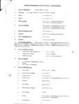
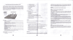
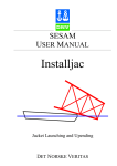
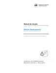
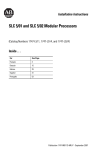
SDK-a6
MCSm86™ SYSTEM DESIGN KIT
o Wire Wrap Area for Custom Interfaces
• Complete Single Board Microcomputer
System Including CPU, rJlemory, and I/O
13
• Easy to Assemble Kit Form
• High Performance 808616-Bit CPU
III
• Interfaces Directly with TTY or CRT
Extensive System Monitor Software in
ROM
Comprehensive Design Library
Included
• Interactive LED Display and &'eyboard
The SDK-86 MCS-86 System Design Kit is a complete single board 8086 microcomputer system in kit form. It contains
all necessary components to complete construction of the kit, including LED display, keyboard, resistors, caps, crys·
tal, and miscellaneous hardware. Included are preprogrammed ROMs containing a system monitor for general soft·
ware utilities and system diagnostics. The complete kit includes an 8-digit LED display and a mnemonic 24-key key·
board for direct insertion, examination, and execution of a user's program. In addition, it can be directly interfaced
with a teletype terminal, CRT terminal, or the serial port of an Intellec system. The SDK-86 is a high performance proto·
type system with designed·in flexibility for simple interface to the user's application.
17-3
SDK·86
FUNCTIONAL DESCRIPTION
A block diagram of the 8086 microprocessor Is shown In
Figure 2.
The SDK-86 is a complete MCS-86 microcomputer system on a single board, In kit form_ It contains all necessary components to build a useful, funCtional system.
Such items as resistors, caps, and sockets are Included.
Assembly time varies from 4 to 10 hours, depending on
the skill of the user. The SDK-86 functional block diagram is shown in Figure 1.
System Monitor
A compact but powerful system monitor is supplied
with the SDK-86 to provide general software utilities and
system diagnostics. It comes in preprogrammed read
only memories (ROMs).
Communications Interface
8086 Processor
The SDK-86 is designed around Intel's 8086 microprocessor. The Intel 8086 is a new generation, high performance microprocessor implemented in N-channel, deple- .
tion load, silicon gate technology (HMOS), and packaged in a 40-pin CerDIP package. The processor
features attributes of both 8-bit and 16-bit microprocessors in that it addresses memory as a sequence
of 8-bit bytes; but has a 16-bit wide physical path to
memory for high performance. Additional features of
the 8086 include the following:
• Direct addressing capability to one megabyte of
memory
• Assembly language compatibility with 8080/8085
• 14 word x 16-bit register set with symmetrical operations
• 24 operand addressing modes
• Bit, byte, word, and block operations
• 8 and 16-byte signed and unsigned arithmetic in
binary or decimal mode, including multiply and divide
• 4 or 5 or 8 MHz clock rate
The SDK-86 communicates with the outside world
through either the on-board light emitting diode (LED)
display/keyboard combination or the user's TTY or CRT
terminal (jumper selectable), or by means of a special
mode in which an Intellec development system
transports finished programs to and from the SDK-86.
Memory may be easily expanded by Simply soldering in
additional devices in locations provided for this purpose. A large area of the board (22 square inches) is laid
out as general purpose wire-wrap for the user's custom
interfaces.
Assembly
Only a few Simple tools are required for assembly: soldering iron, cutters, screwdriver, etc. The SDK-86
assembly manual contains step-by-step instructions for
easy assembly with a minimum of mistakes. Once construction is complete, the user connects his kit to a
power supply and the SDK-86 is ready to go. The monitor
starts immediately upon power-on or reset.
Commands - Keyboard mode commands, serial port
commands, and Intellec slave mode commands are
summarized In Table 1, Table 2, and Table 3, respectively. The SDK-86 keyboard Is shown in Figure 3.
CONTROL
LINES
CONNECTOR
ADDRESS
BUS EXPANSION
CONNECTOR
I
BAUD RATE ~----_I
GENERATOR
L,-=c::..,...J
LED DISPLAY
Figure 1_ SDK-06 System Design Kit Functional Block Diagram
17-4
SDK·86
Documentation
In addition to detailed information on using the monItors, the SDK·86 user's manual provides circuit dia·
grams, a monitor listing, and a description of how the
system works. The complete design library for the
SDK·86 is shown in Figure 4 and listed In the speclflca·
tions section under Reference Manuals.
EXECUTION UNIT
8US INTERFACE UNIT
REGISTER FILE
I R~~~~;t,rI~~E I
SEGMENT
REGISTERS
AND
INSTRUCTION
POINTER
(5 WORDS)
DATA,
POINTER, ANO
INOEX REGS
(8 WORDS)
Figure 4. SDK·86 Design Library
,..--""''''--,...- SHE/57
Table 1_ Keyboard Mode Commands
A'rs.
A,$tS3
Command
Operation
FLAGS
iNfA.RD.WR
3
3
Reset
Starts monitor.
Go
Allows user to execute user
program, and causes it to halt
at predetermined program
stop. Useful for debugging ..
Single step
Allows user to execute user
program one instruction at a
time. Useful for debugging.
Substitute
memory
Allows user to examine and
modify memory locations in
byte or word mode.
Examine
register
Allows user to examine and
modify 8086 register contents.
Block move
Allows user to relocate pro·
gram and data portions in
memory.
Input or output
Allows direct control of
SDK·86 I/O facilities in byte or
mode.
•
DTlR,DEIii,AlE
a·BYTE
INSTRUCTION
QUEUE
T~t ___ r------~~------~
INT--_
NMI---
CONTROL & TIMING
HOLO--HlDA,_--.-.__- .__- . -__- .__"",,",
elK
RESET
READY
Figure 2. 8086 Microprocessor Block Diagram
Table 2. Serial Mode Commands
SYSTM
RESET
INTR
+
REG
C
liP
D
E
IFL
F
8
IW/CS
9
OW/DS
4
IB/SP
5
6
7
OB/BP
MV/SI
EW/DI
1
ER/BX
2
GO/eS
ST/DX
0
EB/AX
A
IISS
Command
Operation
Dump memory
Allows user to print or display
large blocks of memory infor·
mation in hex format than
amount visible on terminal's
CRT display.
Start/continue
display
Allows user to display blocks
of memory information larger
than amount visible on ter·
minai's CRT display.
Punch/read
paper tape
Allows user to transmit fin·
ished programs into and out of
SDK·86 via TTY paper tape
punch.
B
IES
3
Figure 3. SDK·86 Keyboard
17-5
SDK·86
8086 INSTRUCTION SET
Table 4 contains a summary of processor instructions
used for the 8086 microprocessor.
Table 4. 8086 Instruction Set Summary, .
Mnemonic and
Description
Instruction Code
Instruction Code
Data Transfer
10V = 11m:
t a, 4.3
7 I Ii" 3 2 1 0
Register/memory lolllam register
Immediate 10 regislerlmemory
tmmedialelo register
Memory It. accumulator
II 0 0 '0 1 0 d w Imod
reg
Z I'D
1010000 w
7 Iii" 3 Z
'0
71 Ii" 3 2 1 a
rim
110001 t w moo 0 n 0 rim
1011 w reg
data
addr-Iow
Accumulator 10 memory
data itw·'
dala il
w~l
addr-high
adar-h!gh
Register/memory
01010lell
Segment register,
000 reg. 1 10
POP
= Pap:
Register/memory
10001 111
Regisler
01011 fell
Segment/tgister
xeMS
s
1000011 w mod
Aegisterwilhaccumulalor
1 0010 reg
III = Inpul
]-,110010 w
!
\"
I
10110 w
rell
data
10 0 1 1 1 1 1 1
~:"'!-:.;.:;:.:~;"-:"-::'+=mC:-odC:'-='-='-',C:,m:-i
I
11 t-, 0'1 1 w
1101,0100
11110 II W
1 I 11 0 1 1 w
"010101
10011 000
100 I 100 I
7'5431:11
clala il $:w-O,
:t-===.:..J
modI 0 1 rim
00001010
mod 1 10 rim
mod 1 1 I rim
000010'0
Logic
rim
left
SIIR·Shlllloglcal righl
SAR=Shil1arithmelicrighl
RDloRotalelefl
ROR-Rotalerrght
RCl-Rotate through carry flag tell
RCR-Rotale through carry right
POlt
OUT = Oulput
1110011 w
111 0 1 II w
11010111
1 0 0 0 1 1 0 I mod
110 DO 1 0 1 mod
11000 tOO mod
port
AND
r~
r~
r~
<
tIll 011
, 1. 0 I 0 0 v
110100 v
110100 v
1 10-' 0 0 y
11 D·' 0 0 v
110100 v
1 1010 0 ~
W
W
w
w
w
w
modO 1 0
mod 1 00
modI 0 I
mod ,"
modO 0 0
modO 0 1
w modO I 0
w modO 1 1
rim
rIm
11m
rim
rIm
rim
rim
And:
Reg_lmemo,~ and leglster 10 either ~'~':.;'~'~'~'~';;,wofm;:;'e.',.;,,,;;,,,,;;;"m~_--'~--'r--,c-,.,,..-...,....,
rim
rIm
rim
::::::::: ::
\ 0 0 I 11 1 1
:::i~:~:::~ory
F.;~:~:"':~:"':~:":ofm;:;';.d1"""?-,~,=,,,",'m9_"C,.:',::::~:a:.~_~,+--"""'' ' ' ' ' .' '.'....J
~:,:t;r ~;:~:~:':Onnd I~e:li:~:; no rllullr..,-=,-=,-=,7,-:-,::-,w-'-m-.''--,,-,-,-'-'m-O
100 I' II 0
10'01'11.0.0
100 II 101
::::::::: ::::
:~: :::i;:~:;:~ory F.:~;~:~;~:~;::=~:~m;;;od~'~',,:;,:~,:,;;'m9_,;:',,~:'~i:::,._.,'+---""C:"':':"':"':.:.'...J
OR - Or:
Reg_lmemoryandregistertoeither
tmmediatelo register/memory
Immediate to accum'ulator
ArithmetiC
ADD = Add:
:::i~:::;:~ory
71543210
~'i'±'±, ±lOt.tt:=::;;;::J~,;;:,,~,~ifw~'
~::-_~::~p~~a(~~:i~~:rd:ubtract
SIl~/SAl·Shil1togical/arithmetic
Variable pori
Reg.lmemorywithregisterloeilher
rim
rim
tmmedlate With accumulatOr
AAI-ASCII adjust for subtract
"DT-In~ert
Filled pall
:::::::: ::
±,
7154321D
1000regl111
Registerlmemorywllhregisltr
. XLAT~Translate byte to. Al
lEAsload EA to register
LDlsload pointer to OS
LEI~load pointer to ES
LA"f~load AH with !tags
lI\"f~StDle AH into lIags
'UlHFspush lIags
roPF=Pop flags
DOt 1 1 0 d w mod reg
, 0 0000 s w mod I "
modO 0 0 rim
Exchln,l:
fixed porI
Variable port
11&43210
Regjsteflmemor~ and regisler
Immediate With register/memory
I.Ul-lnleger multiply (signed)
AAM-ASClI adjust tor multiply
DIV-Oi~ide (unSigned)
IDIV-Inleger divide (signed)
A"g-ASCII adjust lor divide
CIW-Convert b~te to word
CWD·Convert word to double'word
PUBH = Pulh:
Register
CMP=Colllp.n:
~'~'~'~'~'~'I':::w~m~,[,;,,~,~"m!:l_---'-:-_r--:-:c"-~
,;,:
F.;~:~:~:~:;': ;;.:¥m~'::.:dO;,:';,:,~:"":,;;"m9_.,,,"'::,:~~;a:,.w_'"+-""""-""-'''''w",.,''-.1'
000010 d w mod reg rim
'000000 w modO 0 I rIm
0000110 w
data
data
data IIw·1
datailw-'
XOR = Exclu,IVlII':
Rell.lmemory and register to either
Immediate to register/memory
F.'. ,'-i;'-i;'~'~Od,..w~m~od~"'1;'.;';;;'m~_-"7"--r_=='T1
Fi'",';";"~',..oo,...~m;;;":.;'..;',,,:;~,~:,;;'m9~;:;,,,,~,,,=;-+--,"~=".::.iI.::.W'':'''...J
AOC = Add wllh ;my:
Reg.lmemorywithr~gisler.loeither
Immediate to registerlmemor~
Immediate to accumulator
INC = Incnl'llllnl:
Register/memory .
RegiSI~r
AM-ASCII adjusllor add
W .. o.clmaladjust tor add
lUI
000,100 d w mod reg rim
100000 s w modO 1 0 rim
0001010 w
data
1
0
0
0
data its:w-01
dataitw·1
SIring Manipulation
I 1 1 1 I \ W mod 0 0 0 rim
1 0 0 0 reg
0 I 101I 1
0 10 0 1 1 ,
.1.1.1;'0()'lz
= au.ll'Kt:
Reg./memory and regisler 10 either
:::::::::
:~:: ::i;:::;:~ory
F.'~'~'~'-i;'~';:.';;.w¥m;;;.~':.::,,,,,:-'~'m~_--':;:-_r-==:7.l
MOYS= Move byte/word
CMPS = Compare bytelword
SCAS = Scan byte/word
lOOS = Load byte/~d to AUAX
1'0,100' 0 w
10 100 1 , W
I 0 1 0 1 1 ',w
, ,0 1 0 1 , 0 w
sTDS:,~:Stor:bytEiiwd Ii"'; AUA"";'
'·0" 0 I 0 I 'w
F.;"':"':';:';:';:~:~:+m;;:':.d1~'~':~l:",lm"=-!_~,,::;t:a~i:a~"':'l-t-",,,,,,=-,'"I'",.'""",,,'
Con.trol Tra!"sler
CAll ~ CIII:
Oir.c~
DEC ~ OIenmlnl:
Register/memory
Register
IiIEA-Change sign
25
11 III I 1 W modO 0 1 rIm
0'1001 reg
1II1101lwimodOll rim
Within segment
dlsp-hlQh
Indir~t""'Jhlfl_segmen.'
Dlfec\ intersegrn_enl'Indirectlntersegment
ollseHow
·'seg·low
1 I 1 1 1 111 mod 0 11 rim
o!lset-hlgh
seg-hlQh
continued
17-6
SDK·a6
Table 4. 8086 Instruction Set Summary (Continued)
Mnemonic and
Description
Mnemonic and
Description
Instruction Code
Jlp· Uncandlllon.1 JLlmp:
715432'10
O,ree! wnhm Homen!
1,1101001
Direct wllh'IlHgmenl·shorl
711543210
I
Indlrectwllhln SC\lmenl
dlsp·~IOh
7154321011543210
J
JNS Jump on nol $'lIn
oUseI·low
I
OUSeHIQh
I
uro/eQual
~-~~
Inclueel mlersegmenl
11 I 1 1 11 Illmod 101 "m
l~ro
JCJl·Jump on ex
dlSp
J
11100010
lOOH/lDOP!-LoopwMllewOlcQual
LDBrllllOOP'U lOop.,.h,'enol
mod 1 0 0 rim
1111010101
1011110011.
lOOP loop ex limes
dlsp
11 1 1 1 1 1 1
Olrecllnlersegmenl
11H3210
!lISp· low
11101011
Instruction Code
11100001
11100000
11100011
I
INT
Inl.rrupt
11001101
TvpespeCITlcd
TvpeJ
I~ET
type
11001100
rllTO Interrupt on
o~erllow
\11001110 \
1'100111'1
Interrupl lelum
Processor Control
ClCClearcarry
11111000
eMe Complemenl cal1Y
11110101
STeSelcarry
11111001
elOCleardlteC1l0n
11111100
STO-SeldlreClloll
11111101
eLI Clearlnlerrupl
11111010
Sf!
Set
ml~f(upl
11111011
liLT Hall
1111101001
WAIT Wall
11 0011011
11 1 0 1 1 x x _I mod _
ESC
I
fs~ape
[Iotllernal
de~lnl
lOeKBuslockprelrx
111110000
~
_ rim
I
Notes
Al" 8-bit accumulator
AX" 16-btI accumulator
ex" Count register
OS" Data segment
ES" Extra segment
Abovelbelow refers to unSigned value
Greater"' more positive:
less" less positive (more negative) signed values
(I
d
=,
then "10" reg; if d = a then "from" reg
if w" 1 then word instruction: if w
=
., s.w = 01 then 16 bits 01 Immediate data form the operand.
"s:w= 11 then an immedIate data byte IS Sign extended 1~
form the 16·bit operand.
11'1=0 then "count" =1, il '1=0 then ·'counl'· In (~l)
x=don·' care.
"v = 0 then ·'counr' = 1: II '1=1 then '·count'· In (eLl register.
l IS used lor stnn~ primitives lor comparison With IF FLAG
0 then byte instruction
SEGMENT OVERRIDE PREFIX
001 reg 110
if
if
if
il
mod"
mod"
mod"
mod ~
11 then
00 then
01 then
10 then
if rim" 000 then
if rim" 001 then
if rim" 010 then
if rim = 011 then
if rIm = 100 then
if rim" 101 then
if rim" 110 then
if rim" 111 then
DISP follows 2nd
REG IS assigned accordmg to the loll OWIng table:
rim is treated as a REG field
III-Bill_ ~ II
000 AX
001 CX
010 OX
011 BX
100 SP
101 BP
110 SI
111 DI
DISP " 0·. disp·low and disp·high are absent
OISP " disp·low sign·extended to 16-bits. disp·high IS absent
OISP = disp·high: dlsp·low
EA" (BX) + (51) + OISP
EA '" (BX) + (01) + DISP
EA = (BP) + (51) • DISP
EA" (BP) + (01) + OISP
EA = (51) + DISP
EA ~ (01) .. DISP
EA " (BP) + DISp·
EA" (BX) + DISP
byte of instruction (before data if reqUIred)
~
Segment
00 ES
01 CS
10 SS
11 OS
Instructions which relerence the flag register Ii Ie as a l&bit object use the symbol FLAGS to
represent the liIe:
FLAGS
·except if mod" 00 and rIm
II-BIII_ ~ 01
000 AL
001 CL
010 OL
011 BL
100 AH
101 CH
110 OH
111 BH
110 then EA "disp·high: disp·low
~
X:X:X:X:(OFI:(DFI:IIF):ITFI:(SFI(ZFI.X:(AFIX(PF):X:(CF)
Mnemonics 'c, Intel, 1978
SPECIFICATIONS
AddreSSing
Central Processor
ROM - FEOOO-FFFFF
RAM - 0-7FF (800-FFF available with additional
2142's)
CPU - 8086 (5 MHz clock rate)
Nole
The wlre·wrap area of the SDK·86 PC board may be used for additional
custom memory expansion.
Nole
May be operated at 2.5 MHz or 5 MHZ, jumper selectable, for use with
8086.
Input/Output
Memory
Parallel - 48 lines (two 8255A's)
Serial - RS232 or current loop (8251A)
Baud Rate - selectable from 110 to 4800 baud
ROM - 8K bytes 2316/2716
RAM - 2K bytes (expandable to 4K bytes) 2142
17·7
SDK·86
Interfaces
Electrical' Characteristics
Bus - All signals TIL compatible
Parallel 1/0 - All signals TIL compatible
Serial 1/0 - 20 mA current loop TTY or RS232
DC Power Requirement
(Power supply not included in kit)
Note
The user has access to all bus signals which enable him to design custom system expansions into the kit's wire-wrap area.
Interrupts (256 vectored)
Maskable
Non-maskable
TRAP
Current
3.SA
O.3A
(VTTY required only if teletype is connected)
Environmental Characteristics
Operating Temperature -
DMA
Hold Request input.
0-50·C
Jumper selectable. TTL compatible
Reference Manuals
9800697A SDK-86 MCS-86 System Design Kit
Assembly Manual
9800722 - MCS-86 User's Manual
9800640A - 8086 Assembly Language Programming
Manual
8086 Assembly Language Reference Card
Software
System Monitor - Preprogrammed 2716 or 2316 ROMs
Addresses - FEOOO-FFFFF
Monitor 1/0 - Keyboardldisplay or TIY or CRT (serial
1/0)
Physical Characteristics
Width Height Depth Weight -
Voltage
VCCSV±S%
VTTy-12V±10%
Reference manuals are shipped with each product only
if designated SUPPLIED (see above). Manuals may be
ordered from any Intel sales representative, distributor
office or from Intel Literature Department, 3065 Bowers'
Avenue, Santa Clara, California 95051.
13.5 in. (34.3 cm)
12 in. (30.5 cm)
1.75 in. (4.45 cm)
approx. 24 oz. (3.3 kg)
ORDERING INFORMATION
Part Number
Description.
SDK-86
MCS-86 system design kit
17-8