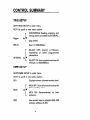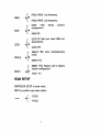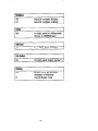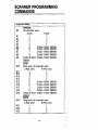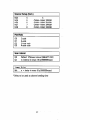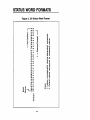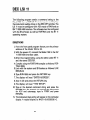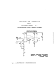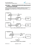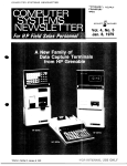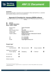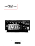
1
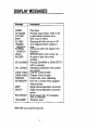
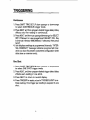
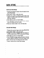
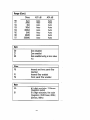
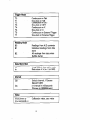
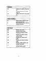
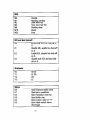
INTRODUCTION
This quick reference guide contains information on front
panel operation and IEEE-488 programming of the Model
199 SystemoMM
as well as the optional Model 1992 Scanner. Also included are programming examples for various
IEEE-488 co”mllers.
01998.
Keith&
Instruments,
Cleveland, Ohio, U.S.A.
Document Number: 199-903-01
Inc.
Rev. A
CONTENTS
...........
SAFETY PRECAUTIONS.
...........
CONTROL SUMMARY.
...........
DISPLAY MESSAGES.
TRIGGERING.
.
DATA STORE.
DMM SETUP
.,..
...........
SCANNER OPERATION..
TYPICAL READING TIMES .._........
DEVICE-DEPENDENT COMF JIANDS.....
SCANNER PROGRAMMING COMMANDS.
.. .. .
DATA FORMAT
.
_ ..
STATUS WORD FORMATS. ,.....
SRO MASK AND STATUS EIYTE FORMAT.
,*.___
.,....
TRANSLATOR
. .
CONTROLLER PROGRAMS
_
.
.
.
.
.
.
.
.,
.
.
.
-
.
~
.
_
.
-
.,,
,Y,?
.
.
.
.
.
.-
..,._..,
.
.
.
.
.
i
.
.
j..
_
1~
2
5
6
7~
9
19.
15
16
22
24
25
2.9
29
31
SAFETY PRECAUTIONS
1. Beforeoperation. ground the instrument through a properly earth grounded power receptacle.
Z&fore
servicing. disconnect the instrument from the
power line and all other equipment, and consult the Model
199 Instruction MamaI.
3. Do not touch any terminals while the instrument
on or connected to any other test equipment.
is turned
4.Do not exceed the maximum input levels es stated in the
specifications for the instrument bee the Model 199 Instruction Manuall.
5. Use the special precautions listed in paragraph 2.6 of the
Model 199 Instruction Manual when testing high-energy
circuits.
CONTROL SUMMARY
TRIG SETUP
SHIFT/TRIG SETUP to enter menu.
NEXT to scroll to next menu option
r
CONTINUOUS: Reading, scanning. and
storing mtes controlled bY INTERVAL.
Trigger
‘:’
ONE SHOT.
DELAY
Osec to 999.999sec
c
INTERVAL
“C
SELECT OFF: Interval
depending
on other
parameters.
2175msec.
programmed
SELECT ON: User-programmed
mnsec
to 999.999sec).
interval
DMM SETUP
SHIFTDMM
SETUP to enter menu.
NEXT to scroll to next menu option.
Displays current software revision level.
REV
MUX
IEEE
r
AIV
L
MUX OFF: Turns off eutocal routines for
faster reading rates.
MUX ON:
*ccur*cy.
Recommended
for
best
Use nuneric keeysto program IEEE488
primary address (0.30).
2
FRE(1
r
A/V
L
SAVE
LEDS
DEBUG
r
A/V
L
r
A/I
L
r
A/V
L
FREO=BOHZ.
Line frequency.
FREQ=GOHZ.
Line frequency.
SAVE
YES:
co”fig”ration.
saves
present
SAVE NO
LEDS ON: Test front panel LEDs and
annunciator*.
-LEDS OFFS
DEBUG
mode.
YES:
Enter
troubleshooting
DEBUG NO
RESET YES: Returns Ynit to factory
default configuration.
RESET
L’
Lo
RESET NO
SCAN SETUP
SHIFT/SCAN
SETUP to enter menu.
NEXT to scroll to next menu option.
2 POLE
POLE
.:.
L
4POLE
3
Mode
RATIO
r
MANUAL:
Allows
channel
to be
manua,,y closed with SCANNER key.
A/V-STEP:
Increments one channel per inL
terval p’ trigger.
SCAN. Scans one set of channels per
interval or trigger fminimum time abetween channels).
r
A/V
I-
ON: Channels 2 through
to channel 1.
8 referenced
OFF
Ratio operates only on a fixed ange.
* Range changes will restart et channel
l
1.
* In MANUAL, et least one reading must be taken on channel 1 before attempting to display ratio on channels 2-S
4
DISPLAY MESSAGES
/ Description
I
Message
OVERFL
NO RANGE
NO FUNC
SHIFT
AC ONLY
TRIGGER
OVERRUN
INTERVAL
OVERRUN
UNCAL
NO DATA
NO SCANNER
CAL LOCKED
CHAN 4 MAX
CHAN 8 MAX
CONFLICT
NO REMOTE*
IDDC”
IDDCO’
BIG STRING’
TRANSERR’
‘IEEE-488
Overrange
Pressing range button while in dB
Invalid shifted function entry.
Shift mode in effect.
Selecting dB with unit not in AC.
Unit triggered before reading is
done.
Interval too short for present configuration.
EEPROM failure uoon Dower UD.No data in data store when
recalling.
Pressing SCANNER or SCAN SETUP
with no scanner.
Attempting
calibration with calibration locked.
Channel 4 limit (Cpole)
Channel 8 limit IZ-pole1
Invalid state when calibrating.
Unit not in remote when programming over bus.
Illegal device-dependent
command.
Illegal device-dependent
command
cotion.
Siring longer than 10 characters
with D command.
Translator error.
bus programming
only.
TRIGGERING
1. Press SHIFT TRIG SETUP then uprange or downrange
to select CONTINUOUS trigger made.
2. Press NEXT and then program desired trigger delay (delay
affects only first reading in continuowJ.
3. ~PressNEXT and then use uprangeldownrange for SELECT
OFF (175msecI or user-progammed
(SELECT ON). Key
in interval fl!Smsec-999.999sec)
if selected, then press
NEXT.
4. Unit displays readings at programmed intervals. “INTERVAL OVERRUN” message indicates programmed interval is too short for present instrument configuration (with
data store or scanner only,.
One Shot
1. Press SHIFT TRIG SETUP~then uprange or downrange
to select ONE SHOT trigger mode
2. Press NEXT, and then program desired trigger delay (delay
affects each reading in one shot).
3. Press NEXT to return to normal display.
4. Press TRIGGER or apply pulse to TRIGGER INPUT to initiate reading. One trigger per reading is required in one
shot
6
DATA STORE
Continuous
Data Storage
1. Program the continuous
using TRIG SETUP.
trigger mode and desired interwl
2,Press SHIFT STORE to enter data store..
3,Program the number of readings to store Isize) in the
range of 1 to 500. or select a size of 000 for wrap-amund
data store operation.
4.Press
NEXT to return to normal display.
S.Press TRJGGER to initiate data storage. RCL will blink
when all readings have been stored.
6. Press any function
One-shot
button
to turn off data store.
Data Storage
1. Program the one-shot
trigger mode using TRIG SETUP.
2,Press SHJFT STORE to enter data store.
S.Pmgram the number of readings (size1 in the range of 1
to 500. or select a size of 000 for wrawxound
storage.
4.~Press NEXT to return to normal display.
5.Press TRIGGER to trigger reading and store it One trigger per reading is required in the one-shot trigger mode
G.RCL will flash when all readings
7.Press a function
have been stored.
key to cancel data storage.
7
Recalling
Data
1. Press SHIFT RECALL to enter the recall mode
will display the last stored reading number.
The unit
2.Press NEXT to display the reading.
3. Use uprange or downrange to scroll through readings. The
scroll rate becomes more rapid after holding button in.
4.Press RECALL to display reading
NEXT to return to reading.
5.Press NEXT to exit recall.
number,
then press
Press SHIFT-DMM
SETUP to *ccess
NEXT to scroll through setup menu.
REV--Briefly
displays current
software
modes below. Use
revision
level.
MUX ON/OFF-Use uprange or downrange to select on/off.
Operating unit in MUX OFF turns off autocal routines, which
speeds up reading rate and minimizes noise spikes at input. Accuracy is reduced in MUX OFF.
IEEE-Use numeric keys to program IEEE-488 primary address JO-30). Use SAVE to permanently change address.
FREQ=50/60HZ-Use
uprange or downrange to select
operating frequency. Selected frequency must agree with
power line frequency for optimum noise performance.
SAVE YES/NO-Select
operating modes then SAVE YES to
store present instwment
configuration.
Unit will assume
the saved configuration upon power up, or after receiving
IEEE-488 DCL or SDC commands.
LEDS ON/OFF-Use
uprange or downrange
NEXT to ten front panel LEDS.
then press
DEBUG ON/OFF-Use
uprange or downrange then press
NEXT to enter diagnostic program. Press any key except
TRIGGER to exit program.
RESET YES/NO-Select
RESET YES with uprange or
downrange to return the unit to factory default conditions.
Use SAVE after RESET to restore power up default to factory default conditions.
9
SCANNER OPERATION
Manual
Channel
Control
1. Press SHIFT SCAN SETUP, then program 2Wpole
with uprange or downrange.
2.Press NEXT, then select MANUAL
or downrange
mode
mode with uprange
3.Press NEXT. then select ratio onloff
downrange.
with
uprange
or
4.Press NEXT to return to normal display.
&Press SCANNER followed by the number of the channel
to close 11-8). The unit will display the closed channel
number in the right-most digit.
6. Press SCANNER 0 to open any closed channel and return
to normal operation.
Step Mode
1. Press SHIFT SCAN SETUP, and program 2/4 pole mode.
2.Press NEXT, then use uprange/downrange
STEP mode.
to select
3.Press NEXT, and select ratio on or off as desired,
4.Press NEXT to return to normal operation.
S.For interval scanning, use TRIG SETUP to select continuous trigger mode, delay, and to program the desired
interval between channels.
&For triggered scanning, use TRIG SETUP to select oneshot trigger mode and delay.
7.Press SCANNER, then program the desired channel limit
fmaximum limit = 4 for 4pole mode).
8.lf interval scanning was selected. the unit will begin
scanning one channel per interval. The closed channel
will appear in the display.
10
!Xlf triggered scanning was selected, press TRIGGER fo
start the scan. One trigger per channel will be required.
lO.To exit the scan mode, press SCANNER 0.
scan
Mode
1. Press SHIFT SCAN SETUP, and program 2/4pole
Z.Press NEXT. then use uprangeldownrange
SCAN mode.
mode.
to select
3.Press NEXT, and select ratio on or off as desired.
4.Press NEXT to return to normal aperation.
S.&x interval scanning, use TRIG SETUP to select continuous trigger mode, delay, and to program the desired
interval between setsof channels.
&For trigge&
shot trigger
scanning, use TRIG SETUP to select onemode and delay.
7.Press SCANNER, then program the desired channel limit
haximum
limit = 4 for 4-p&
mode).
S.lf interval scanning was selected, the unit will begin
scanning one set of channels per interval. The closed
channel will appear in the right-most digit of the display.
S.lf triggered scanning was selected, press TRIGGER to
start the scan. One triggerper
set of channels will be
required.
lO.Ta exit the scan mode, press SCANNER 0.
Interval
Ema store
Scanning
1. Press SHIFT TRIG SETUP, and select CONTINUOUS trigger mode.
2.Press NEXT, and
lOmsec-999.999sec,.
program
11
desired
trigger
delay
3.Press NEXT and choose SELECT OFF (default 176msecI
or SELECT
ON (user
programmed
interval,
15msec-999.999secl.
For SELECT ON, key in desired
interval, then press NEXT.
4.Press SHIFT SCAN SETUP, and select the 2Kpole
mode.
5Press NEXT, and then use uprange or downrange
select the STEP or SCAN mode, as required.
6.Press NEXT, and program
TO
the ratio mode.
7.Press NEXT to return tc normal display.
&Press SHIFT STORE, then program the data store size.
9.Press NEXT to return to normal display.
tO.Press Trigger tc initiate scanning
nel 1 simultaneously.
One-shot
Rigger
and storage on chan-
Data Store Scanning
1. Press SHIFT TRIG SETUP. and select ONE SHOT trigger mode.
2,Press NEXT, and
(Omsec-999.999sec).
program
desired
trigger
delay
3.Press NEXT to return to normal display.
4.press SHIFT SCAN SETUP, and select the Z/4 pole mode
S.Press NEXT, and then use uprange or downrange
select the STEP or SCAN mode. as required.
&Press
to
NEXT, and prcgram the ratio mode
7.Press NEXT tc retur? to normal display.
9.Press SHIFT STORE, then program the dam store size
S.Press NEXT to return to normal display.
10. Ress TRIGGER to initiate scanning and storage on channel 1 simultaneously. One trigger per channel is required
in the STEP mode, and one trigger per set of channels
is required in the SCAN mode.
12
Determining
Scannlng
Interval
l
Scanning without selecting interval
-Program
,NTER”AL SELECT to OFF.
-Interval
is s175msec.
depending on other selected
parameters.
-INTERVAL
OVERRUN message will not be displayed.
l
Minimum
--Interval
1.
2.
3.
4.
Interval Time Calculation
time is the sum of:
(conversions per channel1 x Iconversion
Programmed DELAY time per channel
Break-before-make
time l17msecl
Auto range time (if usedl
-In STEP mode, calculated
setting.
time above is the INTERVAL
-In SCAN mode, (sum of l-41 x (number
scanned) is the minimum interval setting.
l
time1
channels
When using the scanner with STEP or SCAN switching,
the DMM will take readings on each channel as if it were
in the one-shot mode whether programmed to CONTINUOUS or ONE SHOT:
-Conversions
are automatically
synchronized to channel closures. Channels will not close in the middle of
conversions.
-Any programmed DELAY is inserted between channel
closure and start of conversion (with scanner disabled, DELAY is inserted between trigger and start of
conversionI.
13
-Readings
on each channel consist of multiple cower*ions to fill the Running Average User Filter (30 conversions], or Running Average Internal Filter when active 15%d only, varies by range and function; see
me”“al,.
l
Scanner switching is break-before-make.
The time required to change channels is approximately
li’msec,
which~ includes break-before-make relay time settling time
* When using the scanner with ACV or ACA, a DELAYtime
must be programmed to acccmcdate AC converter settling
time
(typically
>lsecl.
See Model
199
specifications.
l
The scanner operates with the set of instrument
parameters programmed prior to start of scanning. Changing any of these parameters, range function, filter, etc.
during scanning will restart the scanner at channel 1. Use
autorange if range changes are required while scanning.
Example
of Fast Scanning
1. Select 3” DC range and function, 4%.digit resolution,
FLTR off.
2. Program ONE SHOT trigger.
3. Select SCAN mode.
4. Select SCANNER “8” to set limit to 8.
S.&e
TRIGGER to initiate a scan of the set of eight
channels.
14
TYPICAL READING TIMES
Typical 5% Digit Conversion
Times
MUX ON, DCV, ACV, ACA: 1lOmsec (133msecl
MUX OFF: 2Smsec 133msecl
MUX ON, OHMS,
L133msecl
MUX OFF: 63msec
3OOkU range
lower:
1lOmsec
l7Smsecl
(Times in parenthesis
vpical
and
Autoranging
are for 50Hz operation1
Times
350msec
1.4sec
500msec
DCV, DCA
ACV, ACA
OHMS l3OOkQ range
and lower1
(Times shown are to correctrange
version times for final reading.)
15
and do not include ccn-
DEVICE-DEPENDENT
COMMANDS
DC current
AC ~wrent
ange
RO
Rl
R2
R3
R4
R5
R6
R7
DCV
ACV
DCA
Auto
3OOilW
3”
3ov
3oov
3oov
3oov
3ODV
AM0
300mV
3v
3ov
3oov
3oov
3oov
3oov
AM0
30mA
3A
3A
3A
3A
3A
3A
16
ACA
AlltO
30mA
3A
3A~
3A
3A
3A
3A
R4
R5
R6
R7
AUt0
3oOn
3kt-l
3OkO
300k0
3MO
30Mn
300Mtl
AUt0
A”*0
A”to
A”,0
Au*0
AlltO
ALli0
Auto
Auto
Auto
A”to
A”,0
Au*0
Au*0
AU0
A”,.,
Zem
20
21
22
PO
P,
P2
Internal and front panel filter
disabled
Internal filter enabled
Front panel filter enabled
Rate
so
Sl
I
4%.digit resolution, 2.59msec
integration period
5%digit
resolution, line cycle
integration (16.67msec. 60Hz;
20msec. 50i-k)
17
Tl
T2
T3
T4
T5
T6
T7
One-shot on Talk
Continuous on %fT
One-shot 0” GET
Continuous on x
One-shot on X
Continuous on External Trigger
Oneshot on External Trigger
Individual
Data store
readings
from data
size
IO
In
Wrap around data store mode
Data S*NB of n In=1 to 5001
Default interval, 175msec
ISELECT OFF)
n=interval
in milliseconds
(15msec to 999999msec)
ValUe
V*n”.“nn”
or
V+n.nnnnnnE+n
Calibration
16
value. zero value
I
I
Calibrate
first point using value
Calibrate third point using value
Default
LO
Ll
G4
G7
Conditions
Restore factory default conditions and save (LlI
Save present machine states as
default conditions
without
Reading
orefix.
&ding
prefix.
Reading,
channel
Reading,
channel
19
prefix.
and channel
with
and channel
without
I
buffer location,
with prefix
buffer location,
without prefix
and
and
MO
Ml
M2
M4
M8
M16
M32
Disable
Reading overflow
Data store full
Data store half full
Reading done
Ready
Error
EOI snd BUS Hold-off
KO
Kl
K2
K3
Enable EOI and bus hold-off on
x
Disable EOI. enable bus hold-off
on x
Enable EOI, disable bus hold-off
on x
Disable both EOI and bus holdoff on x
status
uo
“1
U2
u3
“4
“5
Send machine status word
Send error conditions
Send Translator word list
Send buffer sim
Send current value of ‘V”
Send input switch status
(front/rear)
20
Multiplex
A0
Al
Auto/Cal
Auto/Cal
multiplex
multiplex
disabled
enabled
DdiiY
Wn
n=delay period in milliseconds,
lornsec to 999999msec)
Self-test
JO
Test, ROM, RAM, EzPROM
Hit Button
H”
Hit front panel button
number
Display up to 10 character
message. a=charac*er
Cancel displav mode
21
n
.
SCANNER PROGRAMMING
COMMANDS
Scanner
NO
Setup
MANUAL
All channels
open
2.pole
Nl
N2
N3
N4
N5
N6
N7
N8
N9
NlO
N11
N12
N13
N14
N15
N16
N17
Nl6
N19
N20
N21
N22
N23
CHAN
CHAN
CHAN
CHAN
CHAN
4.pole
1
2
3
4
4 MAX
4 MAX
4 MAX
4 MAX
4 MAX
ERROR
ERROR
ERROR
ERROR
ERROR
CHAN
CHAN
CHAN
CHAN
CHAN
4
4
4
4
4
ERROR
ERROR
ERROR
ERROR
ERROR
1
2
3
4
7
8
CHAN 8 MAX
ERROR
STEP
Stop scan, all channels open
2-W* Limit
4-Pole Limit
1
1
2
2
3
3
45
6
:AX
MAX
MAX
MAX
MAX
CHAN 8 MAX
ERROR
SCAN
Stop scan. all channels open
2-Pole Limit
4Pole Limit
1
1
2
2
3
3
22
N25
N26
N27
N28
7
6
CHAN
CHAN
CHAN
CHAN
4
4
4
4
MAX
MAX
MAX
MAX
ERROR
ERROR
ERROR
ERROR
Scan Interval
00
Qn
Default 175msec interval ISELECT OFF1
n=in*erval in m*ec (15r999999mser.l
Trigger
Delay’
Wn
n = delay in msec l0~999999msec)
‘Delay
to be used as channel settling
23
time
DATA FORMAT
Figure
1. Data Format
STATUS WORD FORMATS
Figure 2. uo status
word Format
U2-U5 Status Words
27
SRQ MASK AND
STATUS BYTE FORMAT
Figure 4. SRQ and Status
28
Byte Format
TRANSLATOR
Translator Words and Characters
Tianslator word
or Character
ALIAS
$
NEW
OLD
SAVE
LIST
FORGET
t
Descrlptlon
Defines Translator words.
Terminates definition string.
Wildcard definition character.
Enables Ranslator.
Disables Translator.
Saves Translator words as powerup default.
Returns list of Translator words.
Purges Translator words from
memory
29
Translator Errors
Display
Message
Description
I
TRANSERR 9
TRANSERR14
TRANSERR15
TRANSERRIG
TRANSERR17
TRANSERR18
TRANSERRIS
TRANSERR20
TRANSERRZl
TRANSERR23
No more Translatar memory’ left.
llse of more than one ALIAS in
definition.
Translator word exceeds 31
characters.
Use of X in a Translator word.
Defined word already exits.
$ character used in definition.
; character sent by itself.
LIST used in definition.
FORGET used in definition
SAVE used in definition.
30
CONTROLLER PROGRAMS
The following programs have been supplied as a simple aid
to the user and are not intended to suit specific needs. Each
program allows you to rend a device-dependent
command
string to the instrument and obtain and display an instrument reading string.
31
IBM PC OR AT
(National
Instruments
GPIB-PC
Interface)
The following program sends a command string from an
IBM PC or AT cdmpuw and displays the instrument reading
string on the ccmputer CRT. The computer must be equipped with the National lnstrumenrs GPIB-PC IEEE-488 interface and the DOS 2.0 or 3.0 operating system. The GPISPC software must be installed and configured as described in the instruction manual.
DIRECTIONS
1. From the front~panel, set the primary address of the Model
199 to 26.
2.With the power off, connect the Model 199 to the
IEEE-486 interface installed in the IBM computer.
3.Type in BASICA on the computer keyboard to get into the
IBM interpretive 8ASIC language.
4.~Place the interface software disk in the default drive, type
LOAD-DEW’, and press *he return key.
5.Add the lines below to the declaration file; also modify
the address in lines 1 and 2, as described in the GPl8PC instruction manual.
6.Run the program and type in the desired command string.
For example, to place the instrument in the ACV function and autorange, type in FlROX and press the return
key.
7.The instrument reading string will then appear on the
A
typical
exampleis:
computer
screen.
NAC”+0.000000E+O.
32
COMMENTS
PROGRAM
Clear screen
Find board descriptor.
Find 199 descriptor.
Set prima,y address to
26.
Set REN true.
Prompt for command
string.
Add <CR>
<LF> to
command string.
Send command string
to 199.
Dimension reading input
string.
Get reading string from
199.
Display reading string
on CRT.
2. In order for Translator to function properly, a <CR>
<LF->seq”ence
must be added to the end of any
Translator exewtion
string sent to the instrument. See
line 65 above for an example
33
IBM PC OR AT
CEC PC-488
Interface
The following program sends a command string from an
IBM PC or AT computer and displays the instrument reading
string on the computer CRT. The computer must be equipped with the Capitol Equipment Corp. PC-468 IEEE-469 interface. The interface card must be set to a memory address of C400,. es described in the PC-466 Instruction
M*lXlal.
DIRECTIONS
1. From the front panel, set the primary address of the Model
199 to 26.
2.With~ the power off, connect the Model 199 to the
IEEE-466 interface installed in the IBM computer.
3.Tum on the computer,
then boot up BASICA.
4.Type in the program lines shown below. using the return
key after each line.
5. Run the program and type in the desired command string
at the command stringprompt.
For erample to place the
in?.trument in the ACV function and autorange, type in
FlROX and press the rewrn key.
6.The instrument reading string will then appear on the
comp”*er
screen.
A
typical
example
is:
NACV+0.000000E+O.
34
COMMENTS
PROGRAM
Set segment address to
C400 hex.
Define call offset*.
Define interface parameters.
Set 199 address to 26.
Initialize PC-466.
Prompt for command
string.
Add <CR> to string.
Send command string to
199.
Dimension reading input
string.
Get reading string from
199.
1. To convert from a string to a numeric variable, modify
the program as follows:
188 R=“RL<“IDb<R*r5,12>
185PRlHTR
>
2. For use with a card memory~address other than C400,
modify the DEFYSEG statement in line 10 accordingly.
For example, with a card memory address of COOO, line
10 should be modified as follows:
19DEFSEC=&HCOBB
3. In order for Translator to function~properly,
a <CR> sequence should be added to the end of any string sent
to the Model 19% See the example is line 66 above.
35
HP SERIES 200 and 300
The following program sends a command string to the
Model 199 from a Hewlett-Packard Series 200 or 300 cornputer and displays the instrument reading Wing on the camputer CRT. The computer must be equipped with the HP16
Interface and BASIC 2.0. 3.0, or 4.0.
1. Fmm the front panel, set the primary address of the Model
199 to 26.
2.Wth the power off, connect the Model 199 to the HPIB
interface installed in the computer.
3.Enter
the computer
EDIT mode.
4,Enter the lines in the program
key after each line
below, using the ENTER
6. Run the pmgram. and type in the desired command string
at the command prompt. For example. to place the instrumentin ACV and autorange. type in FlROX and press the
ENTER key.
6.The instwment reading string will then appear on the CRT
A typical display is: NACV+0.000OOOE+
0.
36
PROGRAM
COMMENT9
Place 199 in remote.
Prompt for and
command.
Address 199 to
send string.
Address 199 to
reading.
Display reading
Repeat.
input
listen,
talk, input
string.
NOTE: For ccnversion fo a numeric variable, change the program as follows:
37
APPLE II
APPLE II IEEE-488 Interface
The following program sends a command string to the
Model 199 from an Apple II computer and displays the instrument reading string on the computer CRT.
The computer must be equipped with the Apple II IEEE-488
Interface installed in slot 3.
DJRECTIONS
1. Fmm the front panel, set the~primav address of the Model
199 to 26.
2.With the power off, connect the Model 199 to the
IEEE-498 interface installed in the Apple ll computer.
3. Enter the lines in the program below. using the RETURN
key after each line.
4. Run the prcgmm and type in the desired command string
at the command prompt. For example, to place the ikstrumen* in ACV and autorange. type in FIROX and press the
return key.
5.The instrument reading string will then appear on the CRT.
A typical display is: NACV+0.00000E+0.
38
PRDGRPiM
COMMENTS
18Z*=CHR*~26>
Terminator.
29 IHPUT ‘COMMAHDSTRING Prompt for and enter
?“;!a
command string.
58 ma5
Set o”tput to IEEE-488
bus.
Define input from
IEEE-488 bus.
Enable remote
Address 199 to listen,
send string.
Line feed on.
Address 199 to talk,
input data.
Untalk the 199.
Define output to CRT.
Define input from
keyboard.
Display reading string.
Repeat.
1. If converSion to numeric
following changes:
variable is required,
make the
2. The Apple II terminates on commas in the data string.
To avoid ~problems, program the Model 199 for the BOG0
or BOG1 data format to eliminate commas.
39
HP MODEL 85
The following program sends a command string to the
Model 199 from an HP-85 computer and displays the instrument reading string an the computer CRT. The campufer must be equipped with the HP82937 GPIB Interface
and an 110 ROM.
DIRECTIONS
1. Fmm the fmnt panel, set the primary address of the Model
199 to 26.
2.With the power off, connect the Model
HP82937A
GPIB interface
installed
in
computer.
199 to the
the HP-85
3. Enter the lines in the program below, using the END LlNE
key after each line.
4.Press the HP-85 RUN key and type in the desired command string et the command prompt. For example, to
place the instrument in ACV and autorange, type in FlROX
and press the END LINE key.
5.The instrument reading string will then appear on the CRT.
A typical dispJey is: NACV+O.OOOOOOE CO.
40
PROGRAM
COMMENTS
Dimension strings.
Place 199 in remote.
Prompt for command.
Input command string.
Address 199 to listen.
send string.
Address 199 tc~ talk, input
reading.
Display reading string.
Repeat
..,
NOTE: For conversion
as follows:
to numeric variable, change line 70
41
HP MODEL 9825A
Use the following program to send a command string to
the Model 199 from a Hewlett-Packard
Model 9825A and
display the instrument reading string an the computer
printer. The computer
must be equipped
with the
HPg8034A HPIB interface and a 9872A extended I/O ROM.
DIRECTIONS
1. From the front~panel. set the primary address of the Model
199 to 26.
2.Wth
the power off, connect the Model 199 to the
98034A HPlB interface installed in the 9825A.
3.Enter the lines in the .p~mgram below, using the STORE
key after each line Line numbers are automaticaliy assigned by the 9825A.
4.Press the 9825A RUN key and type in the desired command string at the command prompt. For example, to
place the instrument in ACV and autorange, type in FlROX
and press the CONT key.
5.The instrument reading string
computer
~p~rint out.
A
NAC”+O.OOOOOOE+O.
42
will then appear on the
typjcal
display
is:
PROGRAM
COMMENTS
Dimension data strings.
Define 199 at address 26.
Place 199 in remote.
Prompt for command
string.
Address 199 to listen,
Address 159 to talk, input
data.
Print data string on
printer.
Repeat.
NOTE: For conversion
gram as follows:
to numeric variable. modify the pro-
43
DEC LSI 11
The following program sends a command string to the
Model 199 from a DEC LSI 11 minicomputer and displays
the instrument reading string on the DEC CRT terminal. The
LSI 11 must be configured with 16K words of RAM and an
IBV 11 IEEE-488 interface The software must be configured
with the ,B software as well 8s FORTRAN and the RT 11
operating system.
DIRECTIONS
1. From the front panel
address of the Model
programfeature, set the primary
199 to 26.
2.With the power off, connect the Mode, 199 to the IBV
11 IEEE-466 interface cable.
3. Enter the program below, using the editor under RT 11
and the name IEEE.FOR.
4. Compile using the FORTRAN compiler as follows: FORTRAN IEEE.
6. Link with the system and IB libraries as follows:
,EEE,IBLIB.
LINK
B.Type~~RUN ,EEE and press the RETURN key.
7.The display will read “ENTER ADDRESS”.
B.Type in 26 and press the RETURN key.
g.The display
will read “TEST SETUP”.
IO. Type in the desired command string and press the
RETURN key For example, to program the instrument
for ACV and autorange, type in FlROX and press
RETURN.
11. The instrument data string will appear on the computer
display. A typical display is: NACV+O.OOOOOOE+O.
44
COMMENTS
PROGRAM
Turn off I9 errors.
Allow 5 error 15’s.
Allow 1 second bus
timeout.
Set line feed as
terminator.
Tim on remote
input primary
address.
Prompt for command
string.
Program instrument.
Address 199 to listen,
send string.
Get data from instrument
Untalk the 199.
Raw%.
45