1
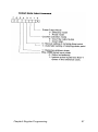
PCL-839
3-axis High Speed
Stepping Motor Control Card
PC-LabCard Series
User’s Manual
Copyright
This documentation and the software routines contained in the PCL-839
software disk are copyrighted 1994 by Advantech Co., Ltd. All rights are
reserved. Advantech Co., Ltd. reserves the right to make improvements in the
products described in this manual at any time without notice.
No part of this manual may be reproduced, copied, translated or transmitted in
any form or by any means without the prior written permission of Advantech
Co., Ltd. Information provided in this manual is intended to be accurate and
reliable. However, Advantech Co., Ltd. assumes no responsibility for its use,
nor for any infringements of the rights of third parties which may result from
its use.
Acknowledgments
PC-LabCard is a trademark of Advantech Co., Ltd. IBM and PC are
trademarks of International Business Machines Corporation. MS-DOS,
Microsoft C and Quick Basic are trademarks of Microsoft Corporation.
BASIC is a trademark of Dartmouth College. Intel is a trademark of Intel
Corporation. Turbo C is a trademark of Borland International.
PartNo.2005839010 2nd Edition
Printed in Taiwan December1994
ii
Contents
Finding you way around in this manual - - - - - - - - - - - - - - - - v
Chapter 1 General information - - - - - - - - - - - - - - - - - - - - - - - 1
Introduction - - - - - - - - - - - - - - - - - - - - - - - - - - - - - - - - - - - - - - 2
Features - - - - - - - - - - - - - - - - - - - - - - - - - - - - - - - - - - - - - - - - - 3
Applications - - - - - - - - - - - - - - - - - - - - - - - - - - - - - - - - - - - - - - 3
Specifications - - - - - - - - - - - - - - - - - - - - - - - - - - - - - - - - - - - - - - 4
Digital input/output - - - - - - - - - - - - - - - - - - - - - - - - - - - - - - - - - 4
General - - - - - - - - - - - - - - - - - - - - - - - - - - - - - - - - - - - - - - - - - 5
Block diagram - - - - - - - - - - - - - - - - - - - - - - - - - - - - - - - - - - - - - 5
Chapter 2 Installation - - - - - - - - - - - - - - - - - - - - - - - - - - - - - - - 7
Switch and jumper settings - - - - - - - - - - - - - - - - - - - - - - - - - - - 8
Setting the PCL-839 Base I/O address (S1) - - - - - - - - - - - - - - - - - 8
Limit Switch Configuration (JP1, JP2, JP3) - - - - - - - - - - - - - - - - - 9
Limit Switch Polarity Setting - - - - - - - - - - - - - - - - - - - - - - - - - - 9
Interrupt level selection (JP4) - - - - - - - - - - - - - - - - - - - - - - - - - - - 11
Hardware Installation - - - - - - - - - - - - - - - - - - - - - - - - - - - - - - - - 12
Installing the card in your computer: - - - - - - - - - - - - - - - - - - - - - - 12
PCL-839 Pin Connections - - - - - - - - - - - - - - - - - - - - - - - - - - - - 13
The 37-pin female connector (CN3) - - - - - - - - - - - - - - - - - - - - - - 14
Example input/output circuit connections - - - - - - - - - - - - - - - - - - 15
Digital Input and Output Connectors (CN1, CN2) - - - - - - - - - - - - - 17
Chapter 3 Prog839 Command Interpreter - - - - - - - - - - - - - - - - - - 19
Introduction - - - - - - - - - - - - - - - - - - - - - - - - - - - - - - - - - - - - - - 20
Using PROG839.EXE with textfiles. - - - - - - - - - - - - - - - - - - - - - 20
PCL-839 Command Set - - - - - - - - - - - - - - - - - - - - - - - - - - - - - - 21
List of commands - - - - - - - - - - - - - - - - - - - - - - - - - - - - - - - - - - 21
Command descriptions - - - - - - - - - - - - - - - - - - - - - - - - - - - - - - - 24
iii
Chapter 4 PCL-839 Software Library - - - - - - - - - - - - - - - - - - Introduction - - - - - - - - - - - - - - - - - - - - - - - - - - - - - - - - - - - - - The 'PCL839.H' Header File - - - - - - - - - - - - - - - - - - - - - - - - - - 'PCL839CX.LIB' Library file - - - - - - - - - - - - - - - - - - - - - - - - - Function Call Descriptions - - - - - - - - - - - - - - - - - - - - - - - - - - -
39
40
40
41
42
Chapter 5 Register Programming - - - - - - - - - - - - - - - - - - - - - PCL-839 Registers - - - - - - - - - - - - - - - - - - - - - - - - - - - - - - - - Programming the PCL-839 - - - - - - - - - - - - - - - - - - - - - - - - - - Command buffers : WR0, WR4 and WR8. - - - - - - - - - - - - - - - - Commands - - - - - - - - - - - - - - - - - - -- - - - - - - - - - - - - - - - - - - Typical Operational Procedures - - - - - - - - - - - - - - - - - - - - - - - -
53
54
60
61
62
72
Appendix A Diagrams - - - - - - - - - - - - - - - - - - - - - - - - - - - - - Jumper and Switch layout - - - - - - - - - - - - - - - - - - - - - - - - - - - PCL-839 Block Diagram - - - - - - - - - - - - - - - - - - - - - - - - - - - - Output Circuit Diagram - - - - - - - - - - - - - - - - - - - - - - - - - - - - - -
81
82
83
84
Appendix B Simple Stepping Motor Driver - - - - - - - - - - - - - 85
Appendix C utility Diskette Contents - - - - - - - - - - - - - - - - - - 91
iv
Finding your way around in this manual
This manual is organized in five chapters, and contains three appendixes
with additional information. The information contained in each chapter
is as follows:
Chapter 1: General Information
If you have just purchased the PCL-839, or just need to brush up on its
Features/specifications, you would want to read this chapter.
Chapter 2: Installation
If you have not yet configured and/or installed your PCL-839, or need to
change the configuration (e.g. set a different base address), this chapter
will give you the information you require.
Chapter 3: PROG839Commandlnterpreter
This chapter describes the utility command interpreter included with the
PCL-839. If you want to program the PCL-839, and have not yet used
the command-set of the PCL-839, this utility program is an excellent
tool to help you learn. Chapter 5 describes the PCL-839's hardware
registers. If you are not familiar with these registers, it is advisable to
read Chapter 5 prior to starting with this chapter.
Chapter 4: PCL-839 Software Library
This chapter describes the 'C' libraries and the functions they contain. If
you want to write your own applications in 'C', this chapter will give you
all the information you need. If you are not familiar with the hardware
registers (and the naming conventions) of the PCL-839, read Chapter 5
before continuing with this chapter.
Chapter 5: Register Programming
This chapter describes the PCL-839's hardware registers. It also contains
typical operational procedures that will assist you in program design.
This chapter is a good place to start getting to know and use the
capabilities of the PCL-839 to best suit your application.
V
1
General information
Introduction
The PCL-839 is a high-speed three-axis stepping motor control card that
simplifies stepping motor control, giving you added performance from
your stepping motors.
Three-axis control
The PCL-839 has three single-chip pulse generators on-board, which
enables the simultaneous and independent control of three axis. The
PCL-839 provides digital pulse and directional control (+ and -) for each
stepping motor axis.
User-friendly interface
The PCL-839 has been designed to act as a user-friendly solution for
your stepping motor control applications. Programming the PCL-839 is
very easy. 'C' Libraries are provided and they contain all the command
functions needed for total control of your stepping motors.
Stand-alone interpreter
A stand-alone, non-resident command interpreter, PROGg39.EXE, can
also be used to control your stepping motors without any programming.
Digital I/O
The PCL-839 features 16 digital inputs and 16 digital outputs for general
I/O use (on/off control etc.).
Isolation protection
The PCL-839's PULSE and DIRECTION outputs and five limits input
switches are isolated from the PC side.
2
PCL-839 User’s Manual
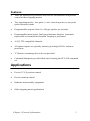
Features
•
Three on-board pulse generators that enables simultaneous independent
control of three stepping motors
•
Two operating modes - two-pulse (+ and - direction pulse) or one-pulse
(pulse-direction) mode
•
Programmable step rate from 1 to 16k pps (pulses per second).
•
Programmable initial speed, final speed and time duration. Automatic
trapezoidal acceleration/deceleration Tamping is performed
•
16 I/O TTL compatible channels
•
All inputs/outputs are optically isolated, providing 500VDC isolation
protection
•
'C' libraries containing device drivers provided
•
Command Interpreter provided that eases learning the PCL-839 command
set
Applications
•
Precise X-Y-Z position control
•
Precise rotation control
•
Robotics and assembly equipment
•
Other stepping-motor applications
Chapter 1 General information
3
4
PCL-839User’s Manual
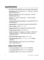
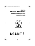
General
· Power consumption: 300mA, +5VDC
· Connector: 37-pin D-type connector
· Board dimensions: 183.5 mm x 99.06 mm
· Operatingtemperature:0 to70°C
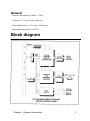
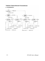
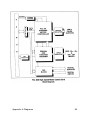
Block diagram
Chapter 1 General information
5
2
Installation
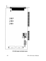
Switch and jumper settings
Before you install the PCL-839, you need to select the card's base address,
set the limit switch configurations and the interrupt level that the card
will use.
This section describes this procedure in detail.
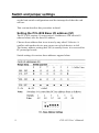
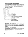
Setting the PCL-B39 Base I/O address (S1)
The PCL-839 requires 16 consecutive I/O addresses. DIP switch S1
(shown below) sets the base I/O address.
Choose abase address that is not in use by any other I/O device. A
conflict with another device may cause one or both devices to fail.
The factory address setting (hex 300) is usually free as it is reserved for
PC prototype boards.
Switch settings for various base addresses appear below:
8
PCL-839 User’s Manual
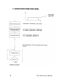
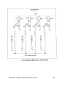
Limit Switch Configuration (JP1, JP2, JP3)
The PCL-839 features 5 limit switches for additional control o f the output.
EL+/ ELThese are the End Limit signal inputs. When the signal of the same direction as
the pulse output (in direction or pulse mode) becomes active, pulse output
stops immediately.
SD+/SDThese are the Slow-Down signal inputs. They are in operation in the
SD-enable mode (refer to the control select modes). When the signal of the
same direction as the pulse output (in direction or pulse mode) becomes active
during high-speed start, the frequency ramps down.
When the signal becomes in-active, the frequency ramps up again.
ORG
This is the Origin point input. When this signal becomes active during origin
return (refer to the control select modes), pulse output stops immediately.
Although the PCL-839 caters for five limit switches, not all of them have to be
operation in one application. Refer to Fig 2-1 (on the next page) for an example
of the use of limit switches.
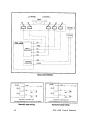
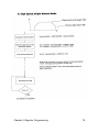
Limit Switch Polarity Setting
JP1, JP2 and JP3 set the polarity for channels C, B and A respectively.
When the jumper is set to LO (normal), the limit switch uses 'normally open' as
default . When the jumper is set to HI, the limit switch uses' normally closed'
as default.
JP1, JP2 and JPJ selection
HI
Normally Closed
LO
Normally Open
The figures on the next page illustrate limit switch use and settings.
Chapter 2 Installation
9
10
PCL-839 User's Manual
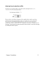
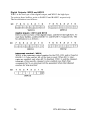
Interrupt level selection (JP4)
You have to set jumper JP4 to select the card's interrupt level (2, 4, 5,
7, 10, 11, 12 or 15), as shown below:
Card interrupt (default = 7)
Do not select a level that is being used by another device unless you have
performed special programming to share several devices on one interrupt.
You can also control interrupt generation by software. If the interrupt is
enabled by software, and the PCL-839 completes a motion, it will generate an
interrupt. Your program can then determine which channel caused the interrupt
by reading the status register.
Chapter 2 Installation
11
Hardware Installation
After you have set the base address, limit-switch configuration and the
interrupt level (as described in the previous section), you will be ready to
install the card in your PC's chassis. The following section will assist you in
installing the PCL-839.
Warning!
Disconnect power from your PC whenever you install or
remove the PCL-839 or its cables
Installing the card in your computer:
1.
Turn off the computer and all peripheral devices (such as printers
and monitors).
2.
Disconnect the power cord and any other cables from the back of
the computer. Turn the chassis so that the back of the unit faces
you.
3.
Remove the chassis cover (see your computer users guide if
necessary).
4.
Locate the expansion slots at the rear of the unit and choose an
unused slot.
5.
Remove the screw that secures the expansion slot cover to the
chassis. Save the screw to secure the PCL-839.
6.
Carefully grasp the upper edge of the PCL-839 card. Align the
hole in the retaining bracket with the hole on top of the expansion
slot, and align the gold striped edge connector with the expansion
slot socket. Press the board firmly into the socket.
7.
Replace the screw in the expansion slot retaining bracket.
8.
Replace the chassis cover.
9.
Connect the D-37 male connector to the PCL-839's 37-pin female
connector Connect the connector to your stepping motor driver
according to the specifications outlined in Section 3.1.
10. Connect the cables you removed in step 2. Turn on the computer.
Hardware installation is now complete.
12
PCL-839 User’s Manual
PCL-839 Pin Connections
This section assists you in connecting the PCL-839's 37-pin connector
(located at CN3) to a variety of stepping motor drivers.
The following diagrams give the PCL-839's pin connector
assignments, and offer some examples of input/output circuit
connections from the card to the driver. You should select the
example that best supports your application needs and the capabilities
of your stepping motor driver.
Note: Output circuit diagrams of stepping motor can
be found in Appendix A.
Chapter 2 Installation
13
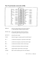
The 37-pin female connector (CN3)
DIR/-dir :
direction signal output(in direction mode) or
(-) direction pulse output (in pulse mode)
PULSE/+dir:
pulse signal output(in direction mode) or
(+)direction pulse output (in pulse mode)
EXTVCC:
external power input
COM :
isolated outputs common point for each channel
EL+ :
(+)direction emergency stop limit switch input
EL- :
(-)direction emergency stop limit switch input
SD+ :
(+)direction slowdown limit switch input
SD- :
(-)direction slowdown limit switch input
ORG :
original (home) point limit switch input
LCOM :
limit switch common point for each channel
14
PCL-839 User’s Manual
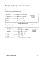
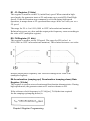
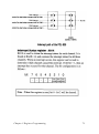
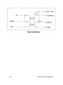
Example input/output circuit connections
The figure below illustrates an isolated output connection from the
PCL-839 to the stepping motor driver
The next figure illustrates a non isolated connection where the PC's
+12 V output bias is used.
Chapter 2 Installation
15
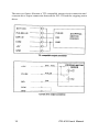
The next two figures illustrate a TTL compatible output circuit connection and
a current-drive output connection between the PCL-839 and the stepping motor
driver.
16
PCL-839 User's Manual
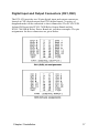
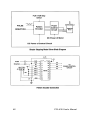
Digital Input and Output Connectors (CN1,CN2)
The PCL-839 provides two 20-pin digital input and output connectors,
located at CNI (digital output) and CN2 (digital input). A variety of
daugtherboards can be connected to these connectors. The PCLD-782B
Isolated D/I board, the PCLD-785B Relay Output Board and the
PCLD-786 SSR & Relay Driver Board are just three examples. The pin
assignments for these connectors are given below.
Chapter 2 Installation
17
3
Prog839 Command Interpreter
Introduction
Included with the PCL-839 card is a utility command-interpreter,
PROG839.EXE. PROG839.EXE is a convenient learning tool for
familiarizing yourself with the command set of the PCL-839, and the
PCL-839 itself. This chapter describes the commands supported by
PROG839.EXE.
It is not recommended for use with stepping motor applications-software
libraries that have been included for that purpose. When you write
applications for your PCL-839, you can either use the included
'C' libraries or directly access the registers of the PCL-839 (as described
in Chapter 4).
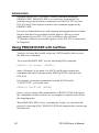
Using PROC839.EXE with textfiles.
PROG839.EXE is driven by commands contained in a ASCII textfile.
You have to create this textfile using any ASCII-capable editor (or use
the DOS edit command).
To execute PROG839.EXE, use the following DOS command :
PROG839 [filename] [ENTER],
where [filename] is the name of a ASCII textfile that contains the
commands that will be interpreted by PROGg39.EXE (and drive the
PCL-839).
For example, to interpret commands from the ASCII textfile
"CURVE.TXT", you would enter
PROG839 CURVE.TXT [ENTER]
Once you have entered this command line, PROG839.EXE will display
the commands from the textfile on you computer's monitor and will run
the stepping motor.
When PROG839.EXE is busy executing the 'script', you can abort this
process by pressing [ESC]. PROG839.EXE will complete the current step
and then exit.
20
PCL-839 User’s Manual
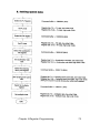
PCL-839aCommand Set
List of commands
Immediate commands
Command & Parameters
/* This is a Comment */
Command Description
BASE (port address)
Set PCL-839 Base Address
ECHO "string"
Display a string on the screen
DEBUG ON
Activate DEBUG mode
DEBUG OFF
Deactivate DEBUG mode (default)
DISPLAY ON
Display the commands on the screen
DISPLAY OFF
Deactivate "DISPLAY ON"
IN port #
Read the value of an input port and display it on the screen
Chapter 3 PROG839.EXE
21
22
PCL-839 User’s Manual
Chapter 3 PROG839.EXE
23
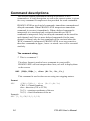
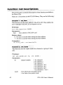
Command descriptions
This section contains information on how to use the PCL-839
command set. A brief description, as well as the correct syntax, is given
for every command. Examples are also provided for some commands.
PROG839.EXE has two kind of commands: immediate commands and
delayed commands. When PROG839.EXE interprets an immediate
command, it executes it immediately. When a delayed command is
interpreted: it is stored and only executed when the next 'RUN'
command is interpreted. Only one delayed command can be stored for
each channel, and if two or more delayed commands (for the same
channel) is found, only the last command will be executed when the
'RUN' command is interpreted. PROG839.EXE is not case-sensitive,
therefore commands in upper-, lower- or mixed- case will be executed
similarly.
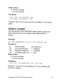
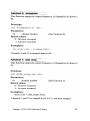
The comment string
/* This is a comment */
The above format is used to leave comments in your textfile.
PROG839.EXE will not interpret these lines, nor will it display them
on the screen.
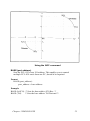
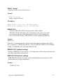
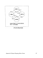
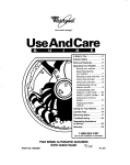
ARC (CH#1 ,CH#2 ,), dira (X1 .Y1 ,.X2 ,,Y2 ,)
This command is used to draw an are using two stepping motors.
Format:
ARC
(CH#1 ,CH#2 ,), dira (X1 .Y1 ,X2 .Y2 )
CH# 1.2 = Channel numbers
dira = direction (CW or CCW)
X1 ,Y1 , = starting coordinates of the are
X2 ,Y2 , = final coordinates of the are
Example:
ARC (1,2),CW(20,5,5,20)
24
PCL-839 User’s Manual
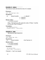
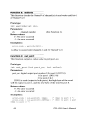
Using the ARC command
BASE (port address)
Sets the PCL-839's base I/O address. This enables you to control
multiple PCL-839 cards form one PC, should it be required.
Format:
BASE (port_address)
port_address = base address
Erample:
BASE (0x2CO) /* Sets the base addr to 2C0 Hex. */
BASE (704)
/* Sets the base addr to 704 Decimal */
Chapter 3 PROG839.EXE
25
26
PCL-839 User’s Manual
ECHO "string"
Displays a line of text on the screen.
Format:
ECHO "string"
string = any line of text
Example(s) :
ECHO “This line will be displayed “
ECHO “The stepper motor is running... “
DEBUG ON
Switches PROG839.EXE to debug mode. In this mode,
PROG839.EXE will display the commands on the screen, but will
not output anything to the stepping motor driver. This enables the
user to check the syntax of the textfile, and the channel parameters.
Format:
DEBUG ON
There are 10 commands that will not affect the output in debug mode. They
are/* comment */, BASE, MANUAL, CLR, ECHO,WAITKEY, WAITTIME,
LOOP, LOOPEND, STATUS and DEBUG OFF.
DEBUG OFF (default setting)
Reverses DEBUG ON (see above). All commands will be interpreted and run
after this command is interpreted.
DISPLAY ON (default setting)
Tells PROG839.EXE to display each command and its parameters on the
screen when it is being interpreted.
Format:
DISPLAY ON
Chapter3 PROG89S.EXE
27
DISPLAY OFF
This inhibits display from PROG839.EXE. There are 4 commands that will
not be affected by this command. They are ECHO, MANU AL, WAITKEY
and WAITDI. Error messages from the PCL-839 will also still be displayed.
Format:
DISPLAY OFF
Example:
DISPLAY OFF
BASE (0x2C0)
DISPLAY ON
The above commands will set the base address to 2C0 (hex) but will not
display anything on the screen.
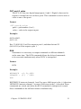
IN port #
The PCL-839 has two digital input ports. One of these ports are read, and the
value displayed on the screen.
Format:
IN port#
Port # is 0 or l
Example:
IN 0
Digital input port O is read, and the value is displayed on the screen.
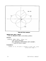
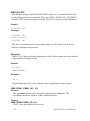
LINE (CH#1, CH#2 ), (X L, YL)
Purpose:
This command draws a line using 2 stepping motor channels. The
coordinates used are relative to the current position.
Format:
LINE (CH#1.CH#2). (X L,YL)
CH#1,2 are the channels to be used
28
PCL-839 User’s Manual
Chapter 3 PROG839.EXE
29
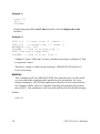
Example 1:
Loop (3)
IN 1
LOOPEND
Digital input port 1 is read 3 times and the value is displayed on the
monitor.
Example 2:
LOOP (3) /* first loop -3 times */
LOOP (2) /* second loop - 2 times */
HSPPMOVE +(1). 200
LOOPEND /* end of second loop */
ECHO "Two moves completed”
LOOPEND /* end of first loop */
Channel 1 moves 200 steps, 2 times, and then a message is displayed. This
is repeated 3 times.
The above syntax is called 'nested looping'. PROG839.EXE allows 10
levels of nesting.
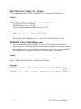
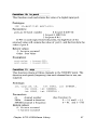
MANUAL
This command will turn PROGg39.EXE into manual mode. In this mode
you can adjust the stepping motor position or the parameters for every
channel manually. The left and right arrow keys are used to step between
the channels. When you have finished adjusting the parameters/position,
press [ESC]. The parameters will be saved and used as the default settings.
Format:
MANUAL
30
PCL-839 User's Manual
OUT port #. value
The PCL-839 has two digital output ports, 0 and 1. Digital values can be
output to external devices on these ports. This command is used to write a
value to one of the ports.
Format:
OUT port#,value
port# = port number (0 or 1)
value = value to be output on port
Example:
OUT 0,OX33
OUT 1.55
Hex 33 (00110011) will be output to port 0, and then decimal 55
(00110111) will be output to port 1.
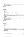
RUN
Sometimes it is necessary to output commands to different channels
at the same time. The RUN command allows the delayed commands
to be executed simultaneously when 'RUN' is interpreted.
Format:
RUN
Example:
HSPPMOVE +(1,2),4000
LSPMOVE - (3 ) . 2000
RUN
HSPPMOVE instructs channels 1 and 2 to move 4000 steps in the (+) direction.
LSPMOVE instructs channel 3 to move 2000 steps in the (-) direction These
commands are stored, and when the RUN command is interpreted, it sends
these commands to the different motors simultaneously
Chapter 3 PROG839.EXE
31
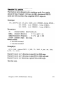
SET (CH# [,CH# [, CH#]]), (FL, FH, AD)
This command is used to set a channel's FL, FH and AD parameters.
Format:
SET (CH# [,CH# [,CH#]]), (FL, FH, AD)
FL(FL speed):l to 16382 pps
FH(FH speed): 1 to 16382 pps
AD (acceleration/deceleration rate): 2 to 1023
Example:
SET (1. 2, 3). (400.3000,300)
This sets all three channels' FL to 400, FH to 3000 and AD to 300.
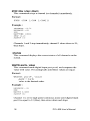
SETMODE (CH# [,CH# [,CH#]]),mode
This command sets the mode for the PCL-839 - either pulse mode or
direction mode. Direction mode means that two signals are used to control
the stepping motor - one for direction and one for step. In pulse mode only
one signal will be applied to either (+) direction or (-) direction.
Format:
SETMODE (CH# [,CH# [,CH#]]),mode
mode = DIR (direction mode) or PUS (pulse mode)
Example:
SETMODE (1.2). DIR /* sets oh 1 & 2 for direction
mode.*/
SETMODE (3). PUS /* sets channel 3 for pulse mode.*/
32
PCL-839 User's Manual
Chapter 3 PROG839.EXE
33
34
PCL-839 User’s Manual
Chapter 3 PROG839.EXE
35
36
PCL-BSS User's Manual
Chapter 3 PROG839.EXE
37
38
PCL-839 User’s Manual
4
PCL-839 Software Library
Introduction
On the floppy disk that came with your PCL-839 card, there are 'C' library files.
These libraries were developed in 'Turbo C', and you should be able do develop
your own stepping motor applications (in 'C') using these files. The source code
for the programming library ('LIB839.C') can also be found on the floppy disk.
This enables you to recompile the libraries for any 'C' compiler (although some
minor changes may be necessary).
The following sections describe the files and functions that will assist you
when you write applications for the PCL-839.
The 'PCL839.H' Header File
To be able to use the functions contained in the software library, you have to
include this header file in your source program (#include "PCL839.H"). This
file contains the headers (Prototypes) for all the functions defined in
LIB839CX.LIR.
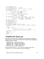
PCL839.H contains the following:
int
int
int
int
int
int
int
int
int
int
int
int
int
int
int
int
int
int
int
int
base = 0x300 ; /* base address . default = 0x300
puls_dir[3] ; /* used by PCL-839~s function */
PO = O :
/* DIO port #O (8bit)
Pi = 1 ;
/* DIO port #1 (8-bit)
P01 = 2 ;
/* DIO port #O h #1 *
CH1 = 1 :
/* Channel #1
CHZ = 2 ;
/* Channel #2
CH3 = 3 ;
/* Channel #3
CH1Z = 4 ;
/* Channel #1 h #2
CH13 = 5 ;
/* Channel #1 & #3
CHZ) = 6 :
/* Channel #Z & #3
CH123 = 7 ;
/* Channel #1.#2 and #3
P_DIR = 0 :
/* Positive (+) direction
N_DIR = l ;
/* Negative (-) direction */
FL = 0 :
/* FL speed */
FH = 1 ;
/* FH speed */
DIR = 0 :
/* Direction mode */
PUS = 1 :
/* Pulse mode */
out_port(int portl_no . int value);
in_port(int port_no);
40
PCL-839 User's Manual
Chapter 4 PCL-839 Software Library
41
42
PCL-839 User's Manual
Chapter 4 PCL-839 Software Library
43
44
PCL-839 User’s Manual
Chapter 4 PCL-839 Software Library
45
46
PCL-839 User's Manual
Chapter 4 PCL-839Software Library
47
48
PCL-839 User’s Manual
Chapter 4 PCL-839Software Library
49
50
PCL-839 User's Manual
Chapter 4 PCL-839Software Library
51
5
Register Programming
PCL-839 Registers
Several registers are used to control the PCL-X39. The PCL-839 uses these
registers to store commands, speed, mode, number of pulses etc. The following
sections describe these registers in detail.
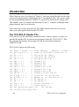
RO : Down-Counter (18 bits)
The down-counter counts down when a pulse is output in manual mode, origin
mode or preset mode. If the counter is stopped in operation mode, counting
ceases. If a pulse is output when the counter has reached 0, the counter reverts
to its maximum number (3FFFF in Hex, 262143 in decimal).
The counter value can be read at any stage - in operation or during standstill.
When reading the value in operation, two quick reads must be done before the
next pulse changes the value of the counter. Compare the two values - if they
are the same then this is the true number of residual pulses.
In preset mode you set the required number of pulses on the counter.
The counter counts down when a pulse is output and pulse generation will stop
when the counter reaches O. The starting range is 00001 (hex) to 3FFFF (hex)
(1 to 262143 in decimal notation). If the counter is set to O when operation is
started, no pulse generation will occur. At that time the operation flag will
indicate the halt condition, but the INT signal is not output.
If counting is interrupted by a deceleration-stop or reset command, the current
counter value is stored, and counting will continue as soon as the startcommand is received. As the counter will be at O when operation is complete,
it is necessary to supply an initial value every time preset mode is started.
54
PCL-839 User’s Manual
R1 : FL Register (13 bits)
This register is used to set the FL (initial/low) speed. When started in highspeed mode, the generator starts at FL and ramps up to reach FH (Final/High
speed). If the deceleration-stop command is received during high-speed
operation, it ramps down to FL speed and then stops. Make sure that you set a
FL speed.
The range for FL is 1 to 8191 (0001 to 1FFF in hexadecimal notation).
Relation between a set value and the output pulse frequency vanes according to
the value of R7 (multiplier register).
R2: FH Register (11 bits)
This register is used to set the FH speed. The range for FH is also 1 to
8191 (0001 to 1FFF in hexadecimal notation). The relation between a set value
and the output pulse frequency also varies according to the value of R7
(multiplier register).
R4:Acceleration (ramping-up)/ Deceleration tramping-down) Rate
Register (10 bits)
This register is used to set acceleration and deceleration characteristics. During
high-speed mode, the generator starts at FL and accelerates to FH.
If the reference clock frequency is (TCLK)[sec], T SUD(the time required
for the ramping-up/ramping-down) is
Chapter5 Register Programming
55
Alternatively, if the ramping-up/ramping-down time is known, R4 can
be calculated as
The range forR4 is 002 (hex) to 3FF (hex) (2 to 1023 in decimal).
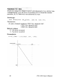
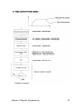
R6 :Ramping-down Point Register (16 bits)
During high-speed operation, the value of the down-counter is compared with
the value of this register. As soon as the value of the counter is less than the
value of this register, ramping-down will start. If the value of R6 is higher than
the down-counter when high-speed mode starts, ramping-up will not occur and
the pulse generation will proceed at FL.
The range forR6 is 0001 (hex) to FFFF (hex) (1 to 65535 in decimal).
The ramping-down point is set in pulses.
* Setting of the ramping-down point
If "automatic setting of ramping-point" is selected for the output mode, no
setting is required for R6. If automatic setting is not selected, the value for R6
has to be calculated and written in the register.
56
PCL-839 User’s Manual
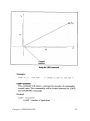
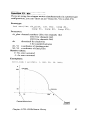
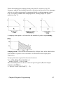
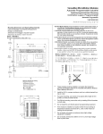
When determining the ramping-down point, the FL frequency, the FH
frequency and the deceleration rate has to be taken into account. If an improper
value is set, pulse output may be terminated halfway during ramping-down
(Fig. A) or may continue after ramping-down, causing longer FL speed
operation (Fig. C).
A ramping-down point is set based on the number of pulses output during
ramping-down. Therefore the area marked by oblique lines in the chart below
is the number of pulses to be calculated. FL and FH are the output pulse
frequencies.
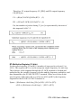
Tsd [sec], the time required for the deceleration is
Tsd = [(R2)-(Rl)]x(R4)/(CLOCK) (1)
where CLOCK = 4.9152 MHz
The relationship between the set value on speed register (Rf) and output
frequency (F [PPS]) is
F = (Rf)x(CLOCK)/[8912x(R7)] (2)
Chapfer5 Register Programming
57
Therefore, FL output frequency FL [PPS] and FH output frequency
FH [PPS] are
FL = (Rl)x(CLOCK)/[8192x(R7)1
(3)
FH = (R2)x(CLOCK)/[8192x(R7)1 (4)
Psd, the number of pulses during T, [sec] is represented by the area of
the trapezoid A-B-C-F
R7:Multiplier Register (10 bits)
For the speed registers, Fl and R2, a number of steps can be selected (1 to
8191). This register (R7) is used to assign an output frequency for one step.
The reference clock inputted through the CLOCK terminal is divided and
multiplied by the variable frequency divider and the frequency multiplier, and
then outputted to the PULSE OUTPUT terminal. When a set value on the
speed register is Rf (where Rf is a value set at R1 and R2), the frequency
outputted at the PULSE OUTPUT terminal is
Fpout = {(Reference clock freq. [Hz] x (Rf)) / (8912 x (R7)}
=(Rf) x {(Reference clock freq.)} / {8912 x (R7)}
58
PCL-839 User’s Manual
When (reference clock)/ [8192 x (R7)1= 1 ... Ix mode
When (reference clock)/ [8192 x (R7)1= 2 ... 2x mode
For the PCL-839, the reference clock frequency is 4.9152 [MHz],
Therefore
(R7)= 600
(=258 hex)
1x mode
(R7)= 300
(=12C hex)
2x mode
The setting range is 002 (hex) to 3FF (hex), which corresponds to 2 to 1023 in
decimal notation. The smaller the set value, the higher the output frequency.
Chapter5 Register Programming
59
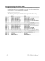
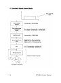
Programming the PCL-839
The PCL-839 stores a selected command in a buffer. This command
remains there until a new command is received. The only command that
can be RESET, is the 'starting mode' command.
I/O Register Control format.
The following table depicts the PCL-839's register I/O address map.
60
PCL-839User's Manual
Chapter 5 Register Programming
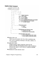
61
Constant speed operation with the FL register. Operates at the speed
set for the FL register.
62
PCL-839 User’s Manual
Chapter 5 Register Programming
63
64
PCL-839 User’s Manual
Chapter 5 Register Programming
65
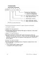
•
PULSE/DIRECTION logic control
PULSE/+dir and DIR/-dir output logic can be changed as follows
66
PCL-839 User’s Manual
Chapfer5 Register Programming
67
68
PCL-839 User’s Manual
Chapter 5 Register Programming
69
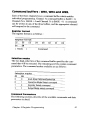
Digital Outputs: WR12 and WR13
WR12 is the low byte of the digital output, and WR13 the high byte.
To write to these buffers, write to BASE12 and BASE13 respectively.
The bit definition is as follows :
70
PCL-839 User’s Manual
Chapter 5 Register Programming
71
72
PCL-839 User’s Manual
Chapter 5 Register Programming
73
74
PCL-839 User's Manual
Chapter 5 Register Programming
75
76
PCL-839 User's Manual
Chapter 5 Register Programming
77
78
PCL-839 User's Manual
Chapter 5 Register Programming
79
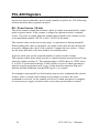
A
Diagrams
82
PCL-839 User's Manual
Appendix A Diagrams
83
84
PCL-839 User's Manual
B
Simple Stepping Motor Driver
86
PCL-839 User's Manual
Appendix B Simple Stepping Motor Driver
87
88
PCL-839 User's Manual
Appendix B Simple Stepping Motor Driver
89
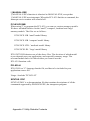
C
Utility Diskette Contents
PCL-839 Utility Diskette
Disk contents
The PCl-839 Utility Diskette contains the following files :
Directory \C
MANUAL.C
MANUAL.EXE
I_MANUAL.EXE
DEMO 1.C
DEMO 2.C
PCL839CS.LIB
PCL839CM.LIB
PCL839CC.LIB
PCL839CL.LIB
PCL839.H
Directory \INTERPRE
PROG839.EXE
CURVE.TXT
SYNTEX.DOC
Program descriptions
PROG839.EXE
PROG839.EXE is a command interpreter for the PCL-839. You can
use this program to learn the PCL-839 function commands.
MANUAL.EXE
MANUAL.EXE is an utility program that enables you to manually control the
motor position, parameters and calibration of the motor position.
92
PCL-839 User's Manual
I_MANUAL.EXE
I_MANUAL.EXE's function is identical to MANUAL.EXE, except that
I_MANUAL.EXE uses interrupts. When the PCL-839 finishes a command, the
interrupt service routine will sound a bell.
PCL838CX.MB
When using 'C' to program the PCL-839, you can use various memory models.
We have included libraries for the 'small', 'compact', 'medium' and 'large'
memory models. The files are as follows:
PCL839CS.LIB -'small' model library
PCL839CS.LIB -'compact' model library
PCL839CS.LTB -' medium' model library
PCL839CS.LIB -' large' model library
PCL839CX.LIB denotes one of the above files. The decision of which model
to use depends one your application, and especially memory usage. The
relevant module has to be linked when you want to use the
PCL-839 function calls.
PCL839.H
PCL839.H is a 'C'-language header file, and has to be included in your
application source-file.
Usage : #include "PCL839.H"
SYNTAX. DOC
SYNTAX.DOC is a documentation file that contains descriptions of all the
commands supported by PROG839.EXE, the interpreter program.
Appendix C Utility Diskette Contents
93