1
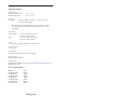
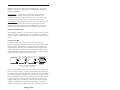
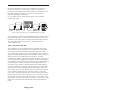
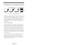
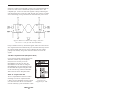
Figure 4–TB5 bus segments can be extended through active hubs.
Termination
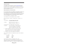
Each end of the segment must be terminated in the characteristic impedance
of the cable. If it is desired to apply termination, connect a 100 ohm ¼ watt
resistor across pins 1 and 2.
Bias
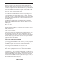
In addition to the termination, it is also necessary to apply bias to the
twisted-pair network so that when the line is
floated differential receivers will not assume an
invalid logic state. Bias is not provided by the
MAU. It is assumed that sufficient bias is
provided by the existing EIA-485 NIMs. Refer
to the appropriate NIM user manual for a more
in depth discussion on bias requirements.
For EIA-485 DC operation, it is very important
1 2 3
that all devices on the wiring segment be
referenced to the same ground potential in order
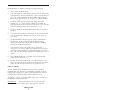
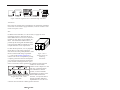
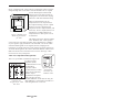
Figure 5–Screw
that the common mode voltage requirement
Terminal Connector
(+/–7 Vdc) of the EIA-485 specification is
Numbering
achieved. This can be accomplished by running
Orientation
a separate ground wire between all computers
or by relying upon the third wire ground of the
power connector assuming that the DC power
return is connected to chassis ground on the computer. Another approach
would be to connect the DC
common of each computer to a cold
water pipe. Connected systems,
each with different elevated
grounds, can cause unreliable
communications or damage to the
Table 1–Screw Terminal Connector Pin EIA-485 differential drivers.
Therefore, it is important that an
Assignments for -485, -485D
adequate grounding method be
and -485X
implemented. Pin 3 on the screw
connector can be used for the common ground connection.
TD877123-0IA
9