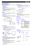
1
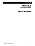
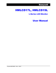
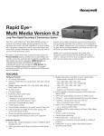
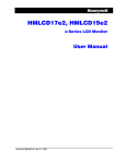
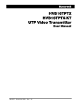
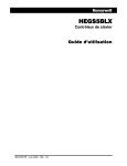
HVBMAXPTZPIT
MAXPRO-Net to PTZ Protocol Translator
User Manual
Document 900.0831 – 09/06 – Rev 1.00
Revisions
Issue
Date
Revisions
1.00
09/06
Initial Release
HVBMAXPTZPIT
CONTENTS
FCC COMPLIANCE STATEMENT . . . . . . . . . . .
CANADIAN COMPLIANCE STATEMENT . . . . . . .
IMPORTANT SAFEGUARDS . . . . . . . . . . . . . .
EXPLANATION OF GRAPHICAL SYMBOLS . . . . . .
WARNINGS . . . . . . . . . . . . . . . . . . . . . . .
INTRODUCTION . . . . . . . . . . . . . . . . . . . .
OPERATION . . . . . . . . . . . . . . . . . . . . . .
SWITCH SETTINGS . . . . . . . . . . . . . . . . . .
Address Selection . . . . . . . . . . . . . .
PTZ Logical Address Ranges. . . . . . . . .
Input Baud Rate Selection . . . . . . . . . .
Input Protocol Selection . . . . . . . . . . .
Output Protocol Selection . . . . . . . . . .
Auto Home Positioning . . . . . . .
Presets . . . . . . . . . . . . . . .
PTZ MODE DEVICE SPECIFIC OPERATION.
Preset Mapping between 80-99. . .
VCL (HD6) PTZ Protocol . . . . . .
Maxpro Mode (HD6) Protocol. . . .
Sensormatic (AD) PTZ Protocol . .
CONNECTIONS . . . . . . . . . . . . . . . . . . . .
Power Connection . . . . . . . . . . . . . .
RS422 Slave Channel. . . . . . . . . . . . .
RS422 Master Channel. . . . . . . . . . . .
I2C Expansion Connection . . . . . . . . . .
MECHANICAL . . . . . . . . . . . . . . . . . . . . .
SPECIFICATIONS . . . . . . . . . . . . . . . . . . .
Rev 1.00
i
.
.
.
.
.
.
.
.
.
.
.
.
.
.
.
.
.
.
.
.
.
.
.
.
.
.
.
.
.
.
.
.
.
.
.
.
.
.
.
.
.
.
.
.
.
.
.
.
.
.
.
.
.
.
.
.
.
.
.
.
.
.
.
.
.
.
.
.
.
.
.
.
.
.
.
.
.
.
.
.
.
.
.
.
.
.
.
.
.
.
.
.
.
.
.
.
.
.
.
.
.
.
.
.
.
.
.
.
.
.
.
.
.
.
.
.
.
.
.
.
.
.
.
.
.
.
.
.
.
.
.
.
.
.
.
.
.
.
.
.
.
.
.
.
.
.
.
.
.
.
.
.
.
.
.
.
.
.
.
.
.
.
.
.
.
.
.
.
.
.
.
.
.
.
.
.
.
.
.
.
.
.
.
.
.
.
.
.
.
.
.
.
.
.
.
.
.
.
.
.
.
.
.
.
.
.
.
.
.
.
.
.
.
.
.
.
.
.
.
.
.
.
.
.
.
.
.
.
.
.
.
.
.
.
.
.
.
.
.
.
.
.
.
.
.
.
.
.
.
.
.
.
.
.
.
.
.
.
.
.
.
.
.
.
.
.
.
.
.
.
.
.
.
.
.
.
.
.
.
.
.
.
.
.
.
.
.
.
.
.
.
.
.
.
.
.
.
.
.
.
.
.
.
.
.
.
.
.
.
.
.
.
.
.
.
.
.
.
.
.
.
.
.
.
.
.
.
.
.
.
.
.
.
.
.
.
.
.
.
.
.
.
.
.
.
.
.
.
.
.
.
.
.
.
.
.
.
.
.
.
.
.
.
.
.
.
.
.
.
.
.
.
.
.
.
.
.
.
.
.
.
.
.
.
.
.
.
.
.
.
.
.
.
.
.
.
.
.
.
.
.
.
.
.
.
.
.
.
.
.
.
.
.
.
.
.
.
.
.
.
.
.
.
.
.
.
.
.
.
.
.
.
.
.
.
.
.
.
.
.
.
.
.
.
.
.
.
.
.
.
.
.
.
.
.
.
.
.
.
.
.
.
.
.
.
.
.
.
.
.
.
.
.
.
.
.
.
.
.
.
.
.
.
.
.
.
.
.
.
.
.
.
.
.
.
.
.
.
.
.
.
.
.
.
.
.
.
.
.
.
.
.
.
.
.
.
.
.
.
.
.
.
.
.
.
.
.
.
.
.
.
.
.
.
.
.
.
.
.
.
.
.
.
.
.
.
.
.
.
.
.
.
.
.
.
.
.
.
.
.
.
.
.
.
.
.
.
.
.
.
.
.
.
.
.
.
.
.
.
.
.
.
.
.
.
.
.
.
.
.
.
.
.
.
.
.
.
.
.
.
.
.
.
.
.
.
.
.
.
.
.
.
.
.
.
.
.
.
.
.
.
.
.
.
.
.
.
.
.
.
.
.
.
.
.
.
.
.
.
.
.
.
.
.
.
.
.
.
.
.
.
.
.
.
.
.
.
.
.
.
.
.
.
.
.
.
.
.
.
.
.
.
.
.
.
. vii
. vii
viii
. x
. x
. 1
. 1
. 2
. 2
. 3
. 3
. 3
. 4
. 4
. 4
. 5
. 5
. 6
. 7
. 7
. 8
. 8
. 8
. 9
. 9
. 11
. 12
900.0831
09/06
Document Title
FIGURES
Figure 1
HVBMAXPTZPIT Typical System Block Diagram. . . . . . . . . . . . . . . . . . . . . . . . 10
Figure 2
HVBMAXPTZPIT Dimensional Drawing . . . . . . . . . . . . . . . . . . . . . . . . . . . . 11
Rev 1.00
iii
Document 900.0831
09/06
HVBMAXPTZPIT User Manual
TABLES
Table 1
DIP Switch Settings for Address Selection . . . . . . . . . . . . . . . . . . . . . . . . . . . . 2
Table 2
PTZ Logical Address Ranges. . . . . . . . . . . . . . . . . . . . . . . . . . . . . . . . . . . 3
Table 3
Input Baud Rate Settings . . . . . . . . . . . . . . . . . . . . . . . . . . . . . . . . . . . . . 3
Table 4
Input Protocol (MAXPRO-Net . . . . . . . . . . . . . . . . . . . . . . . . . . . . . . . . . . . 3
Table 5
Output Protocol . . . . . . . . . . . . . . . . . . . . . . . . . . . . . . . . . . . . . . . . . . 4
Table 6
Auto Home Positioning . . . . . . . . . . . . . . . . . . . . . . . . . . . . . . . . . . . . . . 4
Table 7
Mapped PreSet Commands 80 - 86 . . . . . . . . . . . . . . . . . . . . . . . . . . . . . . . 5
Table 8
Mapped Preset Commands 87-90 . . . . . . . . . . . . . . . . . . . . . . . . . . . . . . . . 5
Table 9
VCL (HD6) PTZ Logical Address Range . . . . . . . . . . . . . . . . . . . . . . . . . . . . . 6
Table 10
Maxpro Mode (HD6) Addresses . . . . . . . . . . . . . . . . . . . . . . . . . . . . . . . . . 7
Table 11
RS422 Slave Channel Pin-Outs. . . . . . . . . . . . . . . . . . . . . . . . . . . . . . . . . . 8
Table 12
RS422 Master Channel . . . . . . . . . . . . . . . . . . . . . . . . . . . . . . . . . . . . . . 9
Table 13
HVBMAXPTZPIT Specifications. . . . . . . . . . . . . . . . . . . . . . . . . . . . . . . . . 12
Rev 1.00
v
900.0831
09/06
TABLES
Rev 1.00
vi
900.0831
09/06
HVBMAXPTZPIT User Manual
FCC COMPLIANCE STATEMENT
Note
This equipment has been tested and found to comply with the limits for a
Class B digital device, pursuant to part 15 of the FCC Rules. These limits are
designed to provide reasonable protection against harmful interference in a
residential installation. This equipment generates, uses and can radiate radio
frequency energy and, if not installed and used in accordance with the
instructions, may cause harmful interference to radio communications.
However, there is no guarantee that interference will not occur in a particular
installation. If this equipment does cause harmful interference to radio or
television reception, which can be determined by turning the equipment off
and on, the user is encouraged to try to correct the interference by one or
more of the following measures:
Reorient or relocate the receiving antenna.
Increase the separation between the equipment and receiver.
Connect the equipment into an outlet on a circuit different from that to which
the receiver is connected.
Consult the dealer or an experienced radio/TV technician for help.
Caution
Changes or modifications not expressly approved by the party
responsible for compliance could void the user's authority to operate
the equipment.
CANADIAN COMPLIANCE STATEMENT
This Class B digital apparatus complies with Canadian ICES-003.
Cet appareil numérique de la Classe B est conforme à la norme NMB-003 du Canada.
Caution
Rev 1.0
Users of the product are responsible for checking and complying with
all federal, state, and local laws and statutes concerning the
monitoring and recording of video and audio signals. Honeywell
Video Systems shall not be held responsible for the use of this
product in violation of current laws and statutes.
vii
900.0831
09/06
HVBMAXPTZPIT User Manual
IMPORTANT SAFEGUARDS
1.
READ INSTRUCTIONS - All safety and operating instructions should be read before
the unit is operated.
2.
RETAIN INSTRUCTIONS - The safety and operating instructions should be retained
for future reference.
3.
HEED WARNINGS - All warnings on the unit and in the operating instructions should
be adhered to.
4.
FOLLOW INSTRUCTIONS - All operating and use instructions should be followed.
5.
CLEANING - Unplug the unit from the outlet before cleaning. Do not use liquid
cleaners or aerosol cleaners. Use a damp cloth for cleaning.
6.
ATTACHMENTS - Do not use attachments not recommended by the product
manufacturer as they may result in the risk of fire, electric shock, or injury to persons.
7.
WATER AND MOISTURE - Do not use this unit near water or in an unprotected
outdoor installation, or any area which is classified as a wet location.
8.
ACCESSORIES - Do not place this product on an unstable cart, stand, tripod, bracket,
or table. The product may fall, causing serious injury to a child or adult and serious
damage to the equipment. Use only with a cart, stand, tripod, bracket, or table
recommended by the manufacturer, or sold with the product. Any mounting of the
product should follow the manufacturer's instructions and should use a mounting
accessory recommended by the manufacturer. Wall or shelf mounting should follow
the manufacturer's instructions and should use a mounting kit approved by the
manufacturer.
9.
A product and cart combination should be moved with care. Quick stops, excessive
force, and uneven surfaces may cause the product and cart combination to overturn.
10. VENTILATION - Slots and openings in the cabinet and the back or bottom are
provided for ventilation and to ensure reliable operation of the equipment and to
protect it from overheating. These openings must not be blocked or covered. The
openings should never be blocked by placing the product on a bed, sofa, rug, or
other similar surface. Equipment should never be placed near or over a radiator or
heat register. This product should not be placed in a built-in installation, such as a
bookcase or rack unless proper ventilation is provided or the manufacturer's
instructions have been adhered to.
11. POWER SOURCES - This product should be operated only from the type of power
source indicated on the marking label. If you are not sure of the type of power
supplied to your facility, consult your product dealer or local power company.
12. GROUNDING OR POLARIZATION - The unit must be connected to a good earth
ground.
13. OVERLOADING - Do not overload outlets and extension cords as this can result in a
risk of fire or electric shock.
14. POWER-CORD PROTECTION - Power supply cords should be routed so that they are
not likely to be walked on or pinched by items placed upon or against them, paying
particular attention to cords and plugs, convenience receptacles, and the point where
they exit from the monitor.
15. OBJECT AND LIQUID ENTRY - Never push objects of any kind into this unit through
openings as they may touch dangerous voltage points or short-out parts that could
result in a fire or electric shock. Never spill liquid of any kind on the unit.
Rev 1.0
viii
900.0831
09/06
HVBMAXPTZPIT User Manual
16. SERVICING - Do not attempt to service this unit yourself as opening or removing
covers may expose you to dangerous voltage or other hazards. Refer all servicing to
qualified service personnel.
17. DAMAGE REQUIRING SERVICE - Unplug the unit from the outlet and refer servicing
to qualified service personnel under the following conditions:
a.
When the power-supply cord or plug is damaged.
b.
If liquid has been spilled, or objects have fallen into the unit.
c.
If the unit has been exposed to rain or water.
d.
If the unit does not operate normally by following the operating instructions.
Adjust only those controls that are covered by the operating instructions as an
improper adjustment of any controls may result in damage and will often require
extensive work by a qualified technician to restore the unit to its normal operation.
e.
If the unit has been dropped or the enclosure has been damaged.
f.
When the unit exhibits a distinct change in performance - this indicates a need for
service.
18. REPLACEMENT PARTS - When replacement parts are required, be sure the service
technician has used replacement parts specified by the manufacturer or have the
same characteristics as the original part. Unauthorized substitutions may result in fire,
electric shock or other hazards.
19. SAFETY CHECK - Upon completion of any service or repairs to this unit, ask the
service technician to perform safety checks to determine that the unit is in proper
operating condition.
20. LIGHTNING AND POWER LINE SURGES - For added protection of this unit during a
lightning storm, or when it is left unattended and unused for long periods of time,
unplug it from the wall outlet and disconnect the cable system. This will prevent
damage to the unit due to lightning and power-line surges.
21. HEAT - The product should be situated away from heat sources such as radiators,
heat registers, stoves, or other products (including amplifiers) that produce heat.
22. INSTALLATION - Do not install the unit in an extremely hot or humid location, or in a
place subject to dust or mechanical vibration. The unit is not designed to be
waterproof. Exposure to rain or water may damage the unit.
23. WALL OR CEILING MOUNTING - The product should be mounted to a wall or ceiling
only as recommended by the manufacturer
Rev 1.0
ix
900.0831
09/06
HVBMAXPTZPIT User Manual
EXPLANATION OF GRAPHICAL SYMBOLS
Caution
The exclamation point within an equilateral triangle advises the user
that failure to take or avoide a specified action could result in loss of
data or damage to the equipment.
WARNING!
The exclamation point within an octagon advises users that
failure to take or avoid a specified action could result in
physical injury to a person or irreversible damage to the
equipment.
WARNING!
To reduce the risk of fire or electric shock, do not expose this
product to rain or moisture.
WARNING!
Do not insert any metallic object through the ventilation
grills.
WARNING!
This unit must be properly grounded to a good earth ground.
Non-observance of this practice may result in a static
electricity build-up that may result in an electric shock when
external connections are touched.
WARNINGS
Rev 1.0
x
900.0831
09/06
INTRODUCTION
The HVBMAXPTZPIT Protocol Interface Translator (PIT) converts Honeywell's Maxpro
serial command protocol to Honeywell’s VCL and Diamond Maxpro mode and
Sensormatic’s (AD) PTZ protocol.
The PIT has two serial communications ports. The RS422/RS485 "Slave" port connects to
the master controller outputting MAXPRO-Net protocol. An RS232 to RS422 converter is
required between the MAXPRO-Net controller and the PIT to convert the MAXPRO-Net
data from RS232 to RS422. The RS422/RS485 "Master" port connects to the PTZ devices.
OPERATION
On power up, both the slave channel and the master channel LEDs will be illuminated.
The PIT unit receives serial messages from the MAXPRO-NET controller, via its slave
communication port. When a valid message is received, the slave port LED will flash off
briefly to indicate message receipt. Only messages addressed to the unit address set up
on DIP switch 2 will be received. Should DIP switch 2 be set to zero (all switches off), then
messages addressed to any PTZ unit will be received by the PIT. The received PTZ
control message will then be translated into the appropriate command, compatible with
the PTZ equipment selected by means of DIP switch 3. This message will be transmitted
out of the master port to one or more PTZ telemetry receivers/domes. When the message
is transmitted, the master port LED flashes off briefly.
If the PTZ protocol supports addressing, the PIT can be set to address zero (broadcast
mode) and each PTZ unit on the master communication port set to a unique address.
There is no limitation in mixing PTZ units/domes as long as the above requirements are
met and there is at least one PIT per translation type.
Should an installation require one or more PIT units for protocol translation, this has no
effect on the connection/operation of standard PTZ units, which are compatible with the
"native" RS422 protocol generated by the master controller.
The PIT takes care of translating fixed speed commands into variable speed commands,
which are automatically ramped from slow to high speed, when the PTZ unit supports
variable speed.
Rev 1.0
1
900.0831
09/06
SWITCH SETTINGS
To access the configuration switches, the two screws on the top cover of the PIT must be
removed. The legend on the cover shows the switches as S1, S2 and S3. Each of these
switch groups has 8 individual switches, marked as 1 through 8. Individual switches are
referred to by the switch group, followed by the switch number. e.g. S1/8. The switch
settings defined in this manual are firmware revision???.
Address Selection
Set switch 2 to the required address of the PIT. This usually matches the camera number
in the system. The actual switch setting is the binary representation of the address. Certain
protocols allow for the addressing of multiple devices on the master communications port
(Broadcast mode). In this case, this DIP switch may be set to address zero, which will pass
all received messages through from the slave to the master port. The following table shows
the first few PIT addresses:
Table 1
DIP Switch Settings for Address Selection
Address
S2/8
S2/7
S2/6
S2/5
S2/4
S2/3
S2/2
S2/1
0
Off
Off
Off
Off
Off
Off
Off
Off
1
Off
Off
Off
Off
Off
Off
Off
On
2
Off
Off
Off
Off
Off
Off
On
Off
3
Off
Off
Off
Off
Off
Off
On
On
4
Off
Off
Off
Off
Off
On
Off
Off
5
Off
Off
Off
Off
Off
On
Off
On
6
Off
Off
Off
Off
Off
On
On
Off
On
On
On
On
On
On
On
On
...
255
Rev 1.0
2
900.0831
09/06
HVBMAXPTZPIT User Manual
PTZ Logical Address Ranges
Switch 3, positions 5 and 6, are used to support below PTZ logical address ranges.
Table 2
PTZ Logical Address Ranges
PIT No.
S3/6
S3/5
Logical Address
Range
1
Off
Off
1 - 255
2
Off
On
257 - 511
3
On
Off
513 - 767
4
On
On
769 - 1023
Input Baud Rate Selection
Switch 3, positions 7 and 8, are used to set the slave port baud rate as per the following
table.
Note
The protocol format is 7 bits, even parity, and 1 stop bit:
Table 3
Input Baud Rate Settings
Baud Rate
S3/8
S3/7
1200 baud
Off
Off
9600 Baud
Off
On
19.2K baud
On
Off
57.6K baud
On
On
Input Protocol Selection
Switch 3, positions 1 to 4 are used to set the protocol the PIT expects to receive on its slave
communications port. The only protocol available is MAXPRO. Ensure S3/1 to S3/4 are set
per the following table.
Table 4
Rev 1.0
Input Protocol (MAXPRO-Net
SW3/4
SW3/3
SW3/2
SW3/1
Protocol
On
On
Off
On
Maxpro
3
900.0831
09/06
Output Protocol Selection
Switch 1, positions 1 to 4, are used to set the PTZ protocol the PIT will transmit on its master
communications channel.
Table 5 Output Protocol
SW1/4
SW1/3
SW1/2
SW1/1
PTZ Protocol
Off
Off
On
Off
VCL (HD6)
(9600 Baud- 8 data bits - No parity -1 stop bit)
On
Off
Off
Off
Maxpro (HD6)
(9600 Baud -8 data bit - Even Parity -1 stop bit)
On
Off
On
Off
Sensormatic (AD)
(4800 Baud - 8 data bits - No parity - 1 stop bit)
Auto Home Positioning
All PTZ units which support preset positioning may take advantage of auto-homing when
used in conjunction with the PIT. To use this feature, switch 1, positions 6 to 7 are used as
follows:
Table 6
Auto Home Positioning
Auto Home Time-out
S1/7
S1/6
Auto-homing disabled
Off
Off
15 seconds
Off
On
1 minute
On
Off
3 minutes 45 seconds
On
On
Should an auto-home time-out value be set, the PTZ will automatically be returned to preset
position 1 after the expiration of the time-out. The time-out is calculated from the time the
PTZ was last moved.
Presets
The valid range for storing and recalling presets is 0-79. Set DIP Switch S1/5 off to store a
preset at 0. Set DIP Switch S1/5 on to write protect preset store at preset 0.
Rev 1.0
4
900.0831
09/06
HVBMAXPTZPIT User Manual
PTZ MODE DEVICE SPECIFIC OPERATION
Preset Mapping between 80-99
The following commands have been implemented for all PTZ protocols by recalling a preset
command.
Table 7
Mapped PreSet Commands 80 - 86
Preset
Command
80
Run Pattern/Tour 1
81
Run Pattern/Tour 2
82
Run Pattern/Tour 3
83
Program Pattern/Tour 1
84
Program Pattern/Tour 2
85
Program Pattern/Tour 3
86
End programming of current pattern/Tour and
store.
Note
VCL (HD6)/Maxpro (HD6) patterns/tours - up to 120 seconds each.
Sensormatic (AD) - the dome stores up to a total of 99 movement
commands in its memory. The End Program command must be
entered if the tour is being stopped before the count down reaches 0
or if the tour is being stopped anywhere in the middle of the presets.
Table 8
Mapped Preset Commands 87-90
Preset
Command
87 - 89
Sensormatic - Clears Tour/Pattern 1 - 3
respectively and resets the dome to Apple Peel
pattern.
VCL (HD6)/Maxpro (HD6) - Starts VectorScans 1 3 respectively.
90
Enter Setup Menu
91
Sensormatic - not used.
VCL (HD6)/Maxpro (HD6) - toggles error table
display on/off
92
Rev 1.0
Toggle Auto-Iris on/off
5
900.0831
09/06
Table 8
Preset
Mapped Preset Commands 87-90
Command
93
Toggle Back Light Compensation (BLC) on/off
94
Toggles between standard operation and
Nightshot Mode (color/black & white). Only
applicable if camera supports the day/night
feature.
95
Sensormatic (AD) - Menu Navigation
VCL (HD6)/Maxpro (HD6) - toggles between freeze
and unfreeze video. Note: for menu navigation use
Iris Open to Enter ad Iris Close to Exit.
96
Sensormatic - Reserved
VCL (HD6)/Maxpro (HD6) - invokes the flashback
function.
97
Reserved
98
Sensormatic - reset dome (soft reset)
VCL (HD6)/Maxpro (HD6) - resets the dome (scan
and camera)
VCL (HD6) PTZ Protocol
The PIT supports a maximum of 128 physical camera addresses when the PTZ output
protocol is set for VCL (HD6). The PIT supports logical address ranges as shown in the
following table.
Table 9
Rev 1.0
VCL (HD6) PTZ Logical Address Range
S1/5
Logical address range
Physical address range
Off
1-128
1-128
On
129-256
1-128
6
900.0831
09/06
HVBMAXPTZPIT User Manual
Maxpro Mode (HD6) Protocol
When in the Maxpro (HD6) mode of operation, only eight (8) cameras may be controlled by
a single PIT in broadcast mode. Selection of which group of 8 cameras may be carried out
by means of DIP switch S1.
For any address outside of this range, a dedicated PIT per HD6 (Maxpro mode) dome is
required.
Table 10
Maxpro Mode (HD6) Addresses
Valid Addresses in
Broadcast Mode
S1/7
S1/6
S1/5
Address 1 to 8 inclusive
Off
Off
Off
Address 9 to 16 inclusive
Off
Off
On
Address 17 to 24 inclusive
Off
On
Off
Address 25 to 32 inclusive
Off
On
On
Address 33 to 40 inclusive
On
Off
Off
Address 41 to 48 inclusive
On
Off
On
Address 49 to 56 inclusive
On
On
Off
Address 57 to 64 inclusive
On
On
On
Sensormatic (AD) PTZ Protocol
The PIT supports a maximum of 255 physical camera addresses (1-255) when set to
Sensormatic PTZ protocol.
Rev 1.0
7
900.0831
09/06
CONNECTIONS
Power Connection
The PIT requires a power source of 9 to 20 VAC, 50/60 Hz, or 10 to 28VDC @ 3VA. When
the PIT44 unit is used with an HVB422FT16 or other VideoBloX expansion module, power
is derived from the system through Pin 6 (PWR+) of the slave channel via an RS422
communication cable.
Note
Pin 6 of the PIT master (output) channel also delivers power (derived from the
VideoBloX system) to devices connected to that channel.
Typically, the external power supply is not required. However, if the master channel load is
comparatively heavy, the user must disconnect Pin 6 power connection from the slave
channel and should use the Honeywell provided +12 VDC power supply 849193-0089. This
power supply runs on a 100-240Vac input. It connects to the PIT via the external power
connector. If the external devices require a higher voltage, another power supply that does
not exceed the PIT power rating can be used.
Caution
Pin 6 of the cable between the Master Device and the Slave Channel
of the HVBMAXPTZPIT must be disconnected when using the external
power supply option to prevent a potential conflict between the two
different power sources.
RS422 Slave Channel
Control messages from the MAXPRO-Net control device, which generates the PTZ control
information, are received on the Slave RS422 port. The MAXPRO-Net control device
outputs RS232 communication so an RS232 to RS422 converter is required between the
MAXPRO-Net device and the PIT. The RS422 configuration allows for multiple PITs to be
connected on a common communications line. Connections are as follows:
Table 11
Pin Number
Rev 1.0
RS422 Slave Channel Pin-Outs
Pin Function
1
RS422 Receive data [-] (from MAXPRO-Net)
2
RS422 Receive data [+] (from MAXPRO-Net)
3
RS422 Transmit data [+] (to MAXPRO-Net)
8
900.0831
09/06
HVBMAXPTZPIT User Manual
Table 11
Pin Number
RS422 Slave Channel Pin-Outs
Pin Function
4
RS422 Transmit data [-] (to MAXPRO-Net)
5
GND (RS422 Communications common)
6
N/C
7
N/C
8
N/C
9
GND (RS422 Communications common)
Should it be required to operate the PIT in RS485 mode, then the TX pair and the RX pair
must be joined together on this connector. i.e. Pin 1 to pin 4 and pin 2 to pin 3.
RS422 Master Channel
Translated control messages, generated by the PIT, are transmitted on this port. The RS422
configuration allows for multiple PTZ receivers to be connected on a common
communications line. Connections are as follows:
Table 12
Pin Number
RS422 Master Channel
Pin Function
1
RS422 Transmit data [-] (to PTZ RS422 Rx[-])
2
RS422 Transmit data [+] (to PTZ RS422 Rx[+])
3
RS422 Receive data [+] (from PTZ RS422 Tx[+])
4
RS422 Receive data [-] (from PTZ RS422 Tx[-])
5
GND (RS422 Communications common [from PTZ
communications common])
6
PWR + (Optional power provided by Aux. Power
Supply)
7
N/C
8
N/C
9
GND (RS422 Communications common [from PTZ
device communications common])
I2C Expansion Connection
The I2C Expansion Connector is not used.
Rev 1.0
9
900.0831
09/06
Figure 1
HVBMAXPTZPIT Typical System Block Diagram.
MAXPRO-Net SERVER
0
I
COM1
COM2
COM7
COM8
DB9- RJ Connector
prov ided by Honey well
RS232
HVB422FT16 RS422 Port Expander
SLAVE
RS422
DB9- RJ Connector
prov ided by Honey well
9
10
11
12
13
14
15
1
2
3
4
5
6
7
16
RS232
PIT
PIN 1
PIN 2
PIN 3
PIN 4
PIN 5
PIN 6
PIN 7
PIN 8
PIN 9
COMBO
-
SLAVE CHANNEL
RS422
HVBMAXPTZPIT
S2 1-on
2-of f
3-of f
4-of f
5-of f
6-of f
7-of f
8-of f
WIRING
PIN 1
PIN 2
PIN 3
PIN 4
PIN 5
PIN 6
PIN 7
PIN 8
PIN 9
S3 1-on
2-of f
3-on
4-on
5-of f
6-of f
7-of f
8-on
RS422
S1 1-of f
2- on
3-of f
4-of f
5-of f
6-of f
7-of f
8-of f
RS422
. CHANNEL
MASTER
SLAVE CHANNEL
RS422
HVBMAXPTZPIT
S2 1-of f
2-on
3-of f
4-of f
5-on
6-of f
7-of f
8-of f
S3 1-on
2-of f
3-on
4-on
5-of f
6-of f
7-of f
8-on
RS422
MASTER. CHANNEL
S1 1-of f
2- on
3-of f
4-of f
5-of f
6-of f
7-of f
8-of f
S2 1-of f
2-of f
3-of f
4-of f
5-on
6-of f
7-of f
8-of f
S3 1-on
2-of f
3-on
4-on
5-of f
6-of f
7-of f
8-on
SLAVE CHANNEL
RS422
PIT422
RS422
MASTER CHANNEL
Subrack16PTZAdd1-128
RS422
Subrack2PTZAdd1-128
S1 1-of f
2- on
3-of f
4-of f
5-of f
6-of f
7-of f
8-of f
C O N VE R T E R
Subrack1PTZAdd1-128
2 3 2 TO 422
RS422
P ow er
1 2 Vol ts D C
PC Con t rol
R S4 8 5 Inpu t
RS48 5
Te rmina ted
R S4 8 5 Inpu t/
U pl in k
O/ P 1
O/ P 2
O/ P 3
O/ P 4
O/ P 5
O/ P 6
O/ P 7
D ata -
D ata +
Sc r een
D ata -
D ata +
Sc r een
D ata -
D ata +
Sc r een
D ata -
D ata +
Sc r een
D ata -
D ata +
Sc r een
D ata -
D ata +
Sc r een
D ata -
D ata +
Sc r een
D ata -
D ata +
Sc r een
19200 Baud
D ata -
4800 Bau d
9600 Bau d
D ata +
2400 Bau d
Sc r een
D ata -
-
D ata +
Sc r een
HDCD8TP Control Output Expander
+
O/ P 8
To PTZs
Rev 1.0
10
900.0831
09/06
HVBMAXPTZPIT User Manual
MECHANICAL
Figure 2
Rev 1.0
HVBMAXPTZPIT Dimensional Drawing
11
900.0831
09/06
SPECIFICATIONS
Table 13
Rev 1.0
HVBMAXPTZPIT Specifications
Power Requirements
10-28V dc or 9-20V ac; 3VA without external load
500mA Fuse
Mechanical
Dimensions: 2.91” (W) x 1.23” (H) x 7.52” (D) [74mm (W) X
31.2 mm (H) X 190.9mm (D)]
Weight: 14 oz. (390g)
Finish: Brushed stainless steel
Environmental
Operating Temperature: 14 to 122 degree F)-10 to +50
degree C)
Storage Temperature: -4 to 149 degree F (-20 to +65
degree C)
Humidity: 0 to 95% RH (non-condensing)
Slave Communications Port
Baud Rate: 9600 Baud, 19.2K Baud, 57.6K baud or 115.2K
baud
Addressing range: Broadcast or 1 to 255
Protocol: MAXPRO-Net
Electrical: RS422, can be wired for RS485.
Master Communications
Port
Baud Rate: From 1200 Baud to 57.6K baud, dependent on
required translation type.
Protocol: Honeywell VCL (HD6), Honeywell Maxpro (HD6),
or Sensormatic (AD)
Electrical: RS422, can be wired for RS485.
Connector Type
RS422 D9 Female
Power 2.0mm DC plug
I2C 6 position RJ45 (4 fitted)
Functions
Pan, tilt, zoom, focus, iris, 64 position presets store and
recall, auxiliary function control.Functions not available on
selected translation target device are excluded.
Other
Switch selectable write protection of preset home position.
Auto homing selectable, off, 15 sec, 1 min or 3 min 45 Sec.
12
900.0831
09/06
Honeywell Video Systems (Head Office)
2700 Blankenbaker Pkwy, Suite 150
Louisville, KY 40299, USA
www.honeywellvideo.com
℡ +1.800.796.2288
Honeywell Video Systems Northern Europe
Netwerk 121
1446 WV Purmerend, The Netherlands
www.SecurityHouse.nl
℡ +31.299.410.200
Honeywell Security Australia Pty Ltd.
Unit 5, Riverside Centre, 24-28 River Road West
Parramatta, NSW 2150, Australia
www.ademco.com.au
℡ +61.2.8837.9300
Honeywell Video Systems UK Ltd.
Aston Fields Road, Whitehouse Ind Est
Runcorn, Cheshire, WA7 3DL, UK
www.honeywellvideo.com
℡ +0844 8000 235
Honeywell Security Asia Pacific
33/F Tower A, City Center, 100 Zun Yi Road
Shanghai 200051, China
www.security.honeywell.com/cn
℡ +86 21.2527.4568
Honeywell Security South Africa
Unit 6 Galaxy Park, 17 Galaxy Avenue
Linbro Park, P.O. Box 59904
2100 Kengray, Johannesburg, South Africa
www.honeywell.co.za
℡ +27.11.574.2500
Honeywell Security Asia
Flat A, 16/F, CDW Building, 388 Castle Peak Road
Tsuen Wan, N.T., Hong Kong
www.security.honeywell.com/hk
℡ +852.2405.2323
Honeywell Security France
Parc Gutenberg, 8, Voie La Cardon
91120, Palaiseau, France
www.honeywell.com/security/fr
℡ +33.01.64.53.80.40
Honeywell Security Italia SpA
Via Treviso 2 / 4
31020 San Vendemiano
Treviso, Italy
www.honeywell.com/security/it
℡ +39.04.38.36.51
Honeywell Security España
Mijancas 1. 3a Planta
P.Ind. Las Mercedes
28022 Madrid, Spain
www.security.honeywell.com/es
℡ +34.902. 667.800
Honeywell Security Deutschland
Johannes-Mauthe-Straße 14
D-72458 Albstadt, Germany
www.honeywell.com/security/de
℡ +49.74 31.8 01.0
Honeywell Security Poland
Chmielewskiego 22a, 70-028
Szczecin, Polska
www.ultrak.pl
℡ +48.91.485.40.60
Honeywell Security Czech Republic
Havránkova 33, Brno
Dolní Heršpice, 619 00, Czech Republic
www.olympo.cz
℡ +420.543.558.111
Honeywell Security Slovakia Republic
Vajnorská 142, 83104 Bratislava
Slovakia
www.olympo.sk
℡ +421.2.444.54.660
www.honeywellvideo.com
+1.800.796.CCTV (North America only)
[email protected]
Document 900.0831 09/06 Rev 1.00
© 2006 Honeywell International Inc. All rights reserved. No part of this publication may be reproduced by any means without written
permission from Honeywell Video Systems. The information in this publication is believed to be accurate in all respects. However,
Honeywell Video Systems cannot assume responsibility for any consequences resulting from the use thereof. The information
contained herein is subject to change without notice. Revisions or new editions to this publication may be issued to incorporate such
changes.