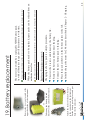
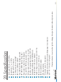
1
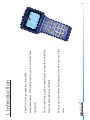
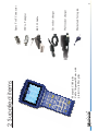
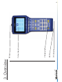
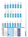
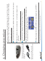
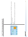
Ver: 1206
User Manual
Advanced Cable Meter
CAM-plus
1
2
3
4
5
6
7
8
9
10
11
12
13
14
15
16
17
18
19
20
Introduction
Supplied items
Overview
Keys
Function keys
Charging procedure
Power up and shut down
Level measurement
QAM measurement
Auto measurement
Spectrum measurement
Tilt measurement
Volt measurement
C/N measurement
File managment
Setup
Setup
Setup
Battery replacement
Specification
Chapter
Table of contents
2
3
4
5
6
7
8
9
10
11
12
13
14
15
16
17
18
19
20
21
Page
1
rain.
Take care of the meter by keeping it warm and out of the
features and options available.
Please read this guide to familiarize yourself with all the
operation.
alignment meter. It should provide years of trouble free
Thank you for purchasing our cable
1. Introduction
2
Maxpeak CAM-plus
Cable Alignment Meter with
protective rubber grips
2. Supplied items
Mains lead for region
Wall socket charger
Car socket charger
RS 232 Cable
IEC to F adapter
Spare F to F Connector
3
3. Overview
DC charging
RS232
Charging light
Colour dispaly
RF-input
4
5
7
4
6
4. Keys
5
1 Soft Function Keys
2 Up Arrow Key
3 Down Arrow Key
4 MHz Key: Frequency key uses for direct frequency input, enter
frequency number and then press frequency key in single
frequency measurement mode. The cursor key uses for moving the
cursor to the frequency number digit which you can turn up or turn
down by pressing the arrow keys in the single frequency and
channel measurement mode.
5 Channel/Enter Key: Channel key uses for direct channel number
input, enter channel number and then press channel key in single
channel measurement mode. It also acts as the ENTER key for
most functions.
6 Left Arrow Key and Clear Key. Clear key uses for deleting any
keyed input made prior to pressing the ENTER key.
7 Right Arrow Key and Decimal Key: Decimal key uses for
entering decimal point in direct frequency input.
8 1-9 Numeric button and Letter Input Key. The key toggles between numeric key and
appropriate English letters.
9 Menu Key. Uses for entering the main menu in any mode.
10 0/* Key. Numeric key “0” and channel setting shortcut key in
single channel measurement mode.
11 Power Key
These symbols explains
the function in the
corresponding function key
In the display window at
the bottom there is
symbols just above the
function buttons
5. Functions keys
Delete file
Load file
Video
measurments
Speaktrum
Left
Go back
QAM
measurments
Right
Speaker vol
Single freq.
measurments
Down
Enter
V/A
measurments
Up
Decrease
value
Increase
value
6
Zoom out
Zoom in
Star to test
Edit
Save file
Only use the included car or wall
socket chargers for charging the meter.
The charging socket is located at the
bottom on the right hand side of the
instrument
1 Some vehicles need ignition turned on in order to provide power to the cigarette lighter socket.
2 Using the instrument while charging may result in less accurate measurements.
During charging the indicator is RED once fully charged it goes GREEN
Press Power key to put the meter in meter mode2 while charging, after
10 minutes the meter returns to the charge screen
Removing the charger from the charging socket puts the instrument in Standby-mode.
Now the battery is charging. A full charge will take 3 hours.
Please note that warranty is not valid if another non supplied charger is used.
Plug the lead from either the included car1 or wall socket chargers to the
instrument.
Locate thecharging socket at the right hand side at the bottom of the instrumet
Charging procedure:
The meter is delivered with a nominal charge only. It needs 24 hours of initial
charge before usage. The battery reaches full capacity after a couple of charges.
6. Charging procedure
7
Press the Power key to switch ON and
OFF the instrument
To turn meter off, keep the “Power Key” button pressed for one
second.
1. LEVEL (Keypad “1”) - Signal level measurement of both analog channel and
digital channel.
2. AUTO (Keypad “2”) - Auto measurement
3. SPECT (Keypad “3”) – Spectrum analysis
4. SCAN (Keypad “4”) –Scan measurement
5. TILT (Keypad “5”) – Tilt measurement
6. VOLT (Keypad “6”) – Voltage measurement
7. C/N (Keypad “7”) – Carrier to noise ratio measurement
8. FILE (Keypad “8”) – File management
9. SETUP (Keypad “9”) – Setup menu
Now use the “Function keys” or arrows to select desired function.
Also the following short keys can be used:
Then the meter moves to the main select screen:
To turn the meter on, keep the “Power Key” button pressed for one
second.
At startup, there will be a welcome screen.
7. Power up and shut down
8
At first set the current channel type. Press “0/*” to display channel setting window.
If the channel type is digital channel, it will display:
Channel – channel number
Select – Marked “√” if the current channel is available.
Type – Digital or analog channels
Freq – Center frequency.
BW – Bandwidth of digital channel.
Mode – Modulation type.
SR – Symbol rate
Save & Return
If the channel type is analog channel, it will display:
Channel – channel number
Select – Marked “√” if the current channel is available
Type – Digital or analog channel
Freq – Video carrier frequency
AIF – Audio IF
Save & Return
Using UP/DOWN arrow key move the cursor and using LEFT/RIGHT arrow key toggle
options or directly enter parameter using keypad. Move the cursor to “Save & Return” and
press F3 or CH/ENTER key after setting the parameters.
In the single digital channel measurement mode, the channel number is shown “CHD”
instead of “CHV” that the analog channel number is shown.
8. Level measurement
9
are is shown
BER value
MER value
In this case both the
If the channel is Digital the QAM measurments can be selected.
9. QAM measurement
10
11
Using UP/DOWN arrow key select an existing file and press F3
to implement the auto test. After the test is finished, press F3 to
save the tested result. The saved file can be viewed in the “FILE
MANAGEMENT” mode.
Using UP/DOWN arrow key select an existing file and press F1
to edit the saved auto test file.
The unit will show the list of files in storage. Using UP/DOWN
arrow key select an empty file and press F1 to create a new auto
test file. Using keypad enter file name, using UP/DOWN arrow
key move the cursor, using LEFT/RIGHT key select the channel
number of No.1 to No.5 channels; Select “Save & Return” and
press F3.
10. Auto measurement
Press F4 to return to the main menu.
Press F3 to save file.
Press UP/DOWN arrow key to change the reference level by 5dB
step.
12
Press LEFT/RIGHT key to move the cursor to see the tested signal
strength.
Press F1 to zoom in and press F2 to zoom out, the BW (bandwidth)
toggles among 15MHz,30MHz, 150MHz.
Using keypad input center frequency and press MHz key, or input
channel number and press CH/ENTER, the unit will show spectrum
analysis.
11. Spectrum measurement
Press F4 to return to the main menu.
13
The max signal strength, min signal strength and their difference display
on the screen.
Signal strengths of 12 channels display in the screen simultaneously.
Press F1 or F2 to select the channel in TILT measurement and press the
LEFT or RIGHT arrow key to change the channel number of selected
channel.
Press F4 to return to the main menu.
Press F3 to save file.
Move cursor to select a channel and press UP/DOWN key to change the
channel number.
The unit will display the max channel number and signal strength; the
min channel number and the signal strength; the difference between the
max and the min.
12. Tilt measurement
Press F4 to return to the main menu.
14
Typically at the cable demarcation point outside the structure, there will
be no trunk voltage.
The battery voltage is also display.
The meter will automatically identify “AC” or “DC” of the trunk
voltage, and display the actual voltage on the screen.
13. Volt measurement
Note:
The function affects when the signal input level is greater than 60 dBuV.
15
Directly input channel number and press “CH/ENTER” key to select the
channel to be tested.
14. C/N measurement.
Press F4 to return to the main menu.
Using UP/DOWN arrow key highlight one file and press F3 to
read the file.
Using UP/DOWN arrow key highlight the file and press F1 to
select one or more files, press F2 to delete selected files.
All the files saved in different measurement modes will be
listed.
15. File managment.
16
16. Setup.
SELECT USER PLAN
Using LEFT/RIGHT key highlight the icon “SELECT USER PLAN” and
press the CH/ENTER key, the meter enters the “SELECT USER PLAN”
menu.
Using UP/DOWN key select the user plan you want and press CH/ENTER
to confirm.
17
LEVEL UNITS
You can select the unit of the meter among:
dBuV
dBmV
dBm
VOLUME SETTINGS
Set the sound volume of the speaker.
DATE & TIME
Set the date & time of the meter.
SHUTDOWN TIME
You can select the auto shutdown time among below options:
3MIN
5MIN
10MIN
ALWAYS ON
17 Setup.
user may also need to re-edit it.
18
to user channel plan, recognizing analog or digital channel. However, due to the complexity of the actual signal, the
The unit will automatically select the channels which signal strength is greater than 40dBuV and collect them in
LEARN USER PLAN
In the main SETUP menu, using the LEFT/RIGHT key highlight the icon
“LEARN USER PLAN” and press the CH/ENTER key, the meter enters the
“LEARN USER PLAN” menu.
Select “USER PLAN 1” or “USER PLAN 2” that you want to create to fit
your CATV system.
The unit will show below content:
1: Please connect to CATV
2: Select channel plan
3. Press F3 to Start
Using the F1, F2 keys to select the channel plan of your TV system and then
press CH/ENTER key to start. After finished select “YES” and press
CH/ENTER key to confirm in the pop-up menu.
Note: The unit needs to access cable television system.
EDIT USER PLAN
In the main SETUP menu, using the LEFT/RIGHT key highlight the icon
“EDIT USER PLAN” and press the CH/ENTER key, the meter enters the
“EDIT USER PLAN” menu.
Using UP/DOWN arrow key highlight the channel and press F3 to enter the
CHANNEL SETUP menu.
Disable the checkbox of “Select” of the channel if you want to omit the
channel in test.Select “Save & Return” after setting up.
18 SETUP.
19
LOAD DEFAULT
If the settings are unexpected and you want to restore the initial settings, select this item and
press F3. The unit will display a confirmation menu:
Are you sure? Yes / No
LIMIT SETUP
In the SETUP menu select LIMIT SETUP and press F3 to enter, it displays the max value
and min value of limitation. Max / Min /Save&Return
The set Limit value will reflect in the SCAN test result.
VALUE AMENDMENT
The meter supplies you such a function to calibrate it manually. The user just needs a
accurate meter or signal generator to compare the measurement value and save calibration
value.
The unit enters value amendment menu.
On the lower left of the screen it displays the amendment value of current channel as “Single
Amend: +0.0” press F1 or F2 to adjust the amendment value and press F3 to save. When
saved successfull green value number turns black.
In this mode you can change the channel number using LEFT/RIGHT arrow key or directly
input the channel number using keypad.
Continue to adjust the amendment value of other channels until finished.
PROBE COMPENSATION
The probe compensation value shows in the bottom of the screen, press F3 to enter. Using
LEFT key or RIGHT key move the cursor and using F1/UP key or F2/DOWN key to increase
or decrease the value. Press F3 to save and return.
Attach the socket of the new battery
to the connector on the instrument.
Put the battery pack in place and put
back the lid and screw.
Take away the battery lid and
disconnect
ne the current battery pack.
Remove the 4 screws located at the
upper back side of the instrument.
Initially charge the meter for 24 hours as described in Chapter 2 - Charging.
Place the pack as shown in the bottom picture to the left.
Connect the new battery pack to the plug.
Remove the battery and disconnect the plug.
Unscrew the 4 screws and take away the battery lid.
Changing the battery pack is a simple procedure.
Battery Replacement:
Do not use any other kind of non original batteries. A different pack can damage the meter and
invalidate the warranty.
20
When the battery pack needs to be replaced, spare packs can be ordered from an
authorised reseller.
To maximize the lifetime of the battery pack, make sure to use/discharge and recharge the meter
frequently
The meter is powered by a replacable NiMH battery pack.
As with all batteries the pack will deteriorate in with time.
19. Battery replacement
The manufacturer reserves the right to change this specification without prior notice
Full band 5 MHz to 870 MHz
Bandwidth 6, 7 or 8 MHz
Replaceable F-connector
75 Ohm imp 20 to 120 dBuV
RF Level as dBm or dBuV
True MER or SNR displayed in dB
RF, BER, MER displayed together
Scan mode to show found channels
Pre and Post BER in numerical value
Full spectrum pixels (zoom 1x2x or 4x)
Backlit colour graphics display 320*240
Integrated rechargeable NiMH battery
Charged from wall or car adaptor
Trunk voltage measurment upto 100 V Ac
Run time in excess of 4 hours
Built in audible sounder
200 channel plans
Tilt mode (up to 12 channels)
Upgrade of settings, firmware and language via computer
210 * 95 * 50 mm , 600 grams
20. Specification
21
Recycle:
Please recycle the carton and packaging.
Do not throw out the NiMH battery, recycle!
Do not discard the meter at the end of useful life, recycle!
Technical department 1:st of February 2012
EN610 10-1:2001 & EMC 61326:1997 & RoHS
We, the manufacturer, Maxpeak AB (publ) Box71, SE-135 22 Tyresö SWEDEN
declares that CAM (cable meter) meets the following standards and directives:
Declaration of conformity:
This product carries a manufactures warranty against faults or manufacturing defects for a period of 12 month
from first registration of the product on the support website www.maxpeak.tv.
Maxpeak reserve the right to replace or repair a faulty meter. The warranty does not cover misuse or damage
caused by dropping the meter or if the meter has been opened.
Warranty
22
[email protected]
23
www.maxpeak.tv