1
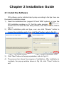
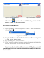
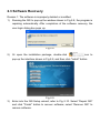
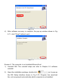
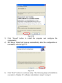
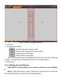
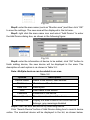
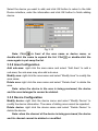
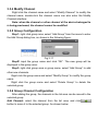
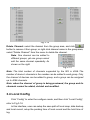
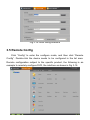
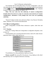
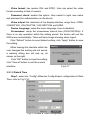
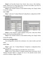
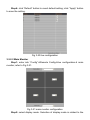
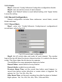
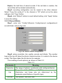
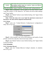
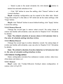
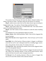
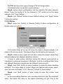
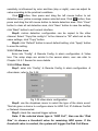
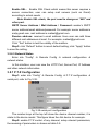
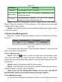
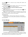
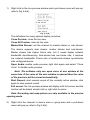
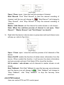
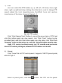
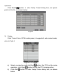
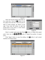
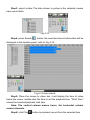
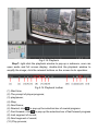
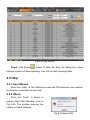
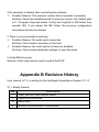
Statement: Contents in this manual may be different from the edition that you are using. There may be technical inaccuracies, or typographical errors in the manual. Should any unsolved problem occur given that the product is used according to this manual, please contact our technical support department or your product suppliers. The content of this manual may be updated at irregular intervals without prior notice. Table of Contents Chapter 1 Welcome to ISS ............................................................................ 6 1.1 Overview .......................................................................................... 6 1.2 Main Features .................................................................................. 6 1.3 Computer Disposition Request ........................................................ 7 1.4 Audience .......................................................................................... 7 1.5 Convention ....................................................................................... 7 Chapter 2 Installation Guide .......................................................................... 9 2.1 Install the Software .......................................................................... 9 2.2 Uninstall Software .......................................................................... 10 2.3 Software Recovery .......................................................................... 11 Chapter 3 Operation and Config ................................................................. 14 3.1 User Login...................................................................................... 14 3.2 Control Panel ................................................................................. 14 3.2.1 Interface Introduction ........................................................... 14 3.2.2 Alarm and Event .................................................................. 16 3.3 Device Manage .............................................................................. 17 3.3.1 Adding Area and Device....................................................... 18 3.3.2 Area Configuration ............................................................... 20 3.3.3 Device Configuration............................................................ 20 3.3.4 Modify Channel .................................................................... 21 3.3.5 Group Configuration............................................................. 21 3.3.6 Group Channel Configuration .............................................. 21 3.4 Local Config ................................................................................... 22 3.5 Remote Config ............................................................................... 23 3.5.1 Basic Configuration .............................................................. 24 3.5.1.1 System ....................................................................... 24 3.5.1.2 Date & Time ............................................................... 25 3.5.1.3 DST ........................................................................... 26 3.5.2 Live Configuration ................................................................ 26 3.5.2.1 Live ............................................................................ 26 3.5.2.2 Main Monitor .............................................................. 27 3.5.2.3 Spot ........................................................................... 28 3.5.2.4 Audio ......................................................................... 29 3.5.3 Record Configuration ........................................................... 29 3.5.3.1 Record Basic ............................................................. 29 3.5.3.2 Record Bitrate ............................................................ 30 3.5.3.3 Snap .......................................................................... 31 3.5.4 Schedule .............................................................................. 31 3.5.4.1 Schedule Record ....................................................... 31 3.5.4.2 Sensor Record ........................................................... 34 3.5.4.3 Motion Record ........................................................... 34 3.5.5 Alarm Configuration ............................................................. 34 3.5.5.1 Sensor ....................................................................... 34 3.5.5.2 Motion ........................................................................ 36 3.5.5.3 Video Loss ................................................................. 37 3.5.5.4 Other Alarm................................................................ 37 3.5.5.5 Alarm Out ................................................................... 38 3.5.6 Network Configuration ......................................................... 38 3.5.6.1 Network ..................................................................... 38 3.5.6.2 Sub Stream ................................................................ 39 3.5.6.3 DDNS ........................................................................ 40 3.5.6.4 Mail ............................................................................ 41 3.5.6.5 Network Status .......................................................... 42 3.5.7 P.T.Z Configuration .............................................................. 42 3.5.8 Account Management .......................................................... 43 3.5.8.1 Add Account............................................................... 43 3.5.8.2 Modify Account .......................................................... 43 3.5.8.3 Delete Account .......................................................... 44 3.5.8.4 Modify Password ....................................................... 44 3.5.9 Advanced ............................................................................. 44 3.6 User Manage ................................................................................. 44 Chapter 4 Software User Guide .................................................................. 46 4.1 Status Icons ................................................................................... 46 4.2 Preview .......................................................................................... 47 4.2.1 Interface Introduction ........................................................... 47 4.2.2 Preview Mode ...................................................................... 48 4.2.3 Stop Previewing ................................................................... 49 4.2.4 Preview Control ................................................................... 49 4.2.5 PTZ Control ......................................................................... 51 4.2.6 Color Adjustment ................................................................. 55 4.3 Video Search ................................................................................. 55 4.3.1 Time Search ......................................................................... 55 4.3.2 File Manage ......................................................................... 58 4.3.3 Event Search ....................................................................... 59 4.3.4 Data Backup ........................................................................ 60 4.4 Log Search..................................................................................... 61 4.5 Help ............................................................................................... 62 4.5.1 User Manual ........................................................................ 62 4.5.2 About.................................................................................... 62 Appendix A FAQ .......................................................................................... 63 Appendix B Revision History ....................................................................... 64 Chapter 1 Welcome to ISS 1.1 Overview The ISS (Intelligent Surveillance System) is the client application specially developed for the embedded network monitoring equipment. The client management software is using C/S architecture, and web-based video management platform. The end user use this system to achieve centralized monitoring, storage, data forwarding, management and control for multiple IP Camera and DVR simultaneously in the LAN or Internet environment, and achieve real-time monitoring, recording, snap picture, two-way voice intercom, data backup, search and playback, remote configuration, PTZ control, alarm control and motion detection, etc. 1.2 Main Features Powerful remote management function Monitor 128 channels at most; manage as many as 4096 channels; preview 64 channels of real-time video monitoring at most, and self-select the quality of preview image and screen display mode Different channels in different devices can be organized to the same group for previewing simultaneously Support two-way voice intercom and audio switch Support electronic amplification, real-time snap picture, color adjustment and other functions in live preview (ISS didn't do electronic amplification temporarily) local store video and audio for real-time preview Support configure snap picture and local record Support dwell configuration for real-time preview (ISS didn't do it temporarily) Support real-time display alarm status of device Support various PTZ protocols and PTZ control Support search and playback in local and remote mode (ISS didn't do local playback temporarily) Support basic playback control, snap picture, fixed-point play, electronic amplification, switching audio, multi-channel comparison and other function when playback (ISS didn't do electronic amplification temporarily) Support remote backup (backup into AVI files) Support remote reboot, remote online upgrade, remote modify parameters, remotely modify the boot LOGO, remote import and export data, remote access to state information, etc (ISS didn't do remote reboot, remote online upgrade and modify LOGO temporarily) Support customize user permissions to view the configuration log, operation log, alarm log and export saved Record modes: Manual, Schedule, Motion detection and Sensor alarm recording Support video cloud function (ISS didn't do it temporarily) Configurable SMTP, DDNS, PPPoE dial-up for devices. 1.3 Computer Disposition Request Operating System: Microsoft Windows XP/ Windows 7; CPU:Intel Pentium IV 3.0 GHz or models above; RAM: 1G or above; Video card:Graphics card is required, and support DirectX 9.0 or above; Audio card:Essential to voice monitoring or two-way voice intercom; 1.4 Audience End users, retailers, professional users and ordinary civilian users, etc. 1.5 Convention Conventions are as follows in this manual: Intelligent Surveillance System referred to as ISS IP Camera、DVR are all referred to as device Click refers to left click mouse; double click refers to double left click the mouse; right click refers to right click mouse Some pictures in this manual is a diagram for reference only, if the picture does not match with the real interface of the software, please make the real interface as the standard Chapter 2 Installation Guide 2.1 Install the Software ISS software can be installed step by step according to the tips. Here are the specific installation steps: 1) Insert the installation disc (support XP and WIN7 system), or copy the 2) 3) 4) ISS installation package to PC, find the setup program , double click it to enter the ISS Setup Wizard, click "Next" button; refer to Fig 2-1: Select installation path and type, user can click "Browse" button to change the installation path, then click "Next" button; refer to Fig 2-2: Fig 2-1 ISS Setup Wizard Fig 2-2 Select Installation Path Click "Next" button in the pop-up window; refer to Fig 2-3: The process bar shows the progress of installation. After installation is complete, the pop-up window shown in Fig 2-4, click "Close" button to exit. Fig 2-3 Confirm Installation Fig 2-4 Installation Complete ISS shortcut appears on the user's PC desktop; double-click this shortcut to enter the user login interface. 2.2 Uninstall Software 1) 2) 3) 4) Go to Start Menu, select “All programs” “ISS” click “Uninstall ISS”; refer to Fig 2-5: Fig 2-5 Uninstall ISS Or go to Start Menu “Control Panel” “Increase / Remove Programs” “ISS” click "delete" button; Pop-up a dialog box, click "Yes" button. When uninstall completed, progress window disappears automatically, and ISS shortcut does not exist in the PC desktop. Note: If user has installed a different version of ISS, please uninstall the previous version and delete the installation directory, and then start the installation. 2.3 Software Recovery Reason 1: The software is improperly deleted or modified. 1) Running the ISS to pop-up the window shown in Fig 2-8, the program is repairing automatically. After completion of the software recovery, the user login dialog box pops up. Fig 2-8 2) Or open the installation package, double-click icon to pop-up the interface shown in Fig 2-9, and then click "install" button. 3) Fig 2-9 Enter into the ISS Setup wizard; refer to Fig 2-10. Select “Repair ISS” and click "Finish" button to recover software; select “Remove ISS” to remove software. 4) Fig 2-10 After software recovery is complete, the pop-up window shown in Fig 2-11, click "Close" button to exit. Fig 2-11 Reason 2: The computer is not installed Microsoft.net. 1) Uninstall ISS. The uninstall steps can refer to Chapter 2.2 software uninstall. 2) Open the installation package, double-click icon to pop-up the ISS Setup interface shown in Fig 2-12. Program has searched the .net components automatically which computer is not installed. 3) Fig 2-12 Click “Accept” button to install the program and configure the 4) components. ISS Setup Wizard will pop-up automatically after the configuration is successful; refer to Fig 2-13: 5) Fig 2-13 Click "Next" button to continue setup. The following steps of installation can refer to Chapter 2.1 software installation step 2 to step 5. Chapter 3 Operation and Config 3.1 User Login When user double-click the ISS shortcut on the desktop or select the ISS in the start menu to run the client program, the user login dialog box pops up, as shown in Fig 3-1: Language: Select the system language of ISS, including Simplified Chinese and English; User: Input the user name. The default user name is “admin”; Password: Input the password. The default password is blank; Input user name and password, and then click “Login” button to enter the ISS client; click "Exit" button to cancel login. Click to automatically save the user name and password, then user does not need to input them again for future login. Note: If the user name or password is incorrect, the warning dialog will pop up. Fig 3-1 User Login 3.2 Control Panel 3.2.1 Interface Introduction The interface of control panel is described as follows: Fig 3-2 control panel interface ① Menu Bar The menu bar includes all functional modules of the software, including control panel, live, video search, config, log search and help. ② Toolbar : Minimize button : Maximize button : Exit button ③ Tab Bar After selecting any function module in the menu bar, they will be added to the tab bar. User can view and switch between multiple functional tabs. The tab of control panel is opened by default after landing; it is always at the first label. The current tab is displayed in orange, non-current labels display in black and gray. When user opens more than five tabs, button appears to the right of the tab bar. Click button to open the drop-down menu, user can switch to already open tabs. When the mouse points to the upper right corner of label, there will appear button, click this button to close label. ④ Functional Area User can enter the system functions and configuration through control panel. The control panel includes 10 common functions, including Live, Time Search, File Manage, Event Search, Remote Backup, etc. ⑤ Alarm Info Area 3.2.2 Alarm and Event 1) Click "Alarm" button to pop up alarm information list; refer to Fig 3-3: Fig 3-3 Alarm information list User can select the alarm type, including motion detection, sensor alarm, video loss, and other alarm. When enabled alarm and triggered an alarm, a small icon will be displayed on the preview area, and the alarm list shows the alarm information of equipment. As shown below: 2) Fig 3-4 Click "Event" button to pop up event information list; refer to Fig 3-5: Fig 3-5 event information list The list shows the record information of equipment. User can select the record type, including motion record, sensor record, schedule record, and manual record. Fig 3-6 The meaning of other buttons in the interface as shown in Table 3-1: Table 3-1 Button Meaning Audio switch, and set the volume Click this button to display more alarm information, click again to hide the list. Switching list display mode Note: Layout and function of Menu Bar, Toolbar, Tab Bar and Alarm Info Area is the same as other tabs. 3.3 Device Manage Config includes four submenus: device manage, local config, remote config and user manage. Click “Config” to enter the configure mode, and then click “Device Manage” to manage the device; refer to Fig 3-7: Fig 3-7 device manage interface ① List area ② Configuration buttons Add the channel to group button Remove the channel from group button Import device info button Export device info button User can export the device information into PC as a local file for backup function, or import device information from PC to the ISS system. ③ Group area 3.3.1 Adding Area and Device Note: Before any operations, you need to add device and configure it. Step1: right click list area, select “Add Area” from the menu to enter the Add Area dialog box, as shown in the following figure: Fig 3-8 Step2: enter the area name (such as “Monitor area”) and then click “OK” to save the settings. The new area will be displayed in the list area. Step3: right click the area name icon and select “Add Device” to enter the Add Device dialog box, as shown in the following figure: Fig 3-9 Step4: enter the information of device to be added, click “OK” button to finish adding device, the new device will be displayed in the area. The description of each option is as shown in Table 3-2: Note: Multiple devices can be added to an area. Table 3-2 Options Device Name Description Name of the device; user‐defined IP Address IP address of the device Data Port Device port User User name of the device Password Password of the device Channel Number Belong Area The channel number of the device Display the area to which the current device belongs; gray meanings disabled Step5: user can also add device by searching device. Click “Search Device” button of Add Device dialog box to search device online. The searched device will be displayed in the list, as shown below. Select the device you want to add, and click OK button to return to the Add Device interface, enter the information and click OK button to finish adding device. Fig 3-10 Note: Click in front of the area name or device name, or double-click the name to expand the list. Click or double-click the name again to put away the list. 3.3.2 Area Configuration Add sub-area: right click the area name and select “Add Area” to add a sub-area; the sub-area may also add sub-area. Modify area: right click the area name and select “Modify Area” to modify the area name; Delete area: right click the area name and select “Delete Area” to delete the area. Note: when the device in the area is being previewed, the device and the area belonged to cannot be deleted. 3.3.3 Device Configuration Modify device: right click the device name and select “Modify Device” to modify the device information. The name of sibling area cannot be repeated. Delete device: right click the device name and select “Delete Device” to delete the device. Note: when the channel of the device is being previewed, the device and its channel cannot be deleted or modified. 3.3.4 Modify Channel Right click the channel name and select “Modify Channel” to modify the channel name; double-click the channel name can also enter the Modify Channel interface. Note: when the channel or other channel of the device belonged to is being previewed, the channel cannot be modified. 3.3.5 Group Configuration Step1: right click group area, select “Add Group” from the menu to enter the Add Group dialog box, as shown in the following figure: Fig 3-11 Step2: input the group name and click “OK”. The new group will be displayed in the group area. Step3: right click group area or group name, select “Add Group” to add other new channels. Right click the group name and select “Modify Group” to modify the group name. Right click the group name and select “Delete Group” to delete the selected group. 3.3.6 Group Channel Configuration After adding the group, the channels in the list area can be moved to the selected group. Add Channel: select the channel from the list area, and click button to move it to the selected group. As shown below: Fig 3-12 Delete Channel: select the channel from the group area, and click button to remove it from group; or right click channel name in the group area, select “Delete Channel” from the menu to delete the channel. Note: One channel can be added to different groups, yet one group cannot add the same channel repeatedly. As shown on the right: Fig 3-13 Note: The total number of channels supported by the ISS is 4096. The number of device’s channels is the number can be added to each group. Only the channel of devices can be added to group, and a group can be assigned up to 4096 channels. Note: when the channel of group is being previewed, the group and its channels cannot be added, deleted and modified. 3.4 Local Config Click “Config” to enter the configure mode, and then click “Local Config”; refer to Fig 3-14: In this interface, user can setup the save path of local snap, data backup and local record, setup the packing time of local record and the hold time of log. Fig 3-14 Local config interface 3.5 Remote Config Click “Config” to enter the configure mode, and then click “Remote Config”. Double-click the device needs to be configured in the list area. Remote configuration subject to the specific product, the following is an example to remotely configure DVR, the interface as shown in Fig 3-15: Fig 3-15 Remote config interface The interface lists all actionable items of remote configuration; user can click item into the relevant configuration. User can also select those items by clicking button of ; click “Remote Config” to return to the interface of Figure 3-15. Note: The user who has the authority of remote configuration double-clicks the device in order to enter the main interface of remote configuration, otherwise it will prompt this user has not operating authority. “Remote Config” includes nine submenus: Basic, Live, Record, Schedule, Alarm, Network, P.T.Z, Account and Advanced. 3.5.1 Basic Configuration Basic configuration includes three submenus: system, date time and DST. 3.5.1.1 System Enter into “Config”Remote Configbasic configurationsystem; refer to Fig 3-16. In this interface user can setup the device name, device ID, video format, password check, video output and so on. Fig 3-16 system configuration The definitions for every parameters display as below: Device name/ID: the name/ID of the device. It may display on the client end that help user to recognize the device remotely. Video format: two modes: PAL and NTSC. User can select the video format according to that of camera. Password check: enable this option. User needs to input user name and password for authentication on the device. Video output: the resolution of live display interface, range from: CVBS, VGA800*600, VGA1024*768, VGA1280*1024 and HDMI. Device Language: setup the menu language. Here is disabled. Screensaver: setup the screensaver interval time (30/60/180/300s). If there is no any operation within the setting period, the device will exit the OSD menu automatically. There will have image showing when logout. Click “Default” button to resort default setting; click “Apply” button to save the setting. When leaving the interface within the user changed the setting and not saved, a warning dialog box will pop up, as shown on the right: Click "OK" button to save the setting; click "Cancel" button to exit the current interface. Fig 3-17 3.5.1.2 Date & Time Step1: enter into “Config”Remote Configbasic configuration Date Time; refer to Fig 3-18: Fig 3-18 Date & Time configuration Step2: set the date format, time format, time zone in this interface, enable “Manual set” to setup device time; user also can enable “sync time” to synchronize device time with NTP server. Step3: Click “Default” button to resort default setting; click “Apply” button to save the setting. 3.5.1.3 DST Step1: enter into “Config”Remote Configbasic configuration DST; refer to Fig 3-19: Fig 3-19 DST configuration Step2: in this interface, enable daylight saving time, setup time offset, mode, start & end month/week/date, etc. Step3: Click “Default” button to resort default setting; click “Apply” button to save the setting. 3.5.2 Live Configuration Live configuration includes four submenus: live, main monitor, spot and audio. 3.5.2.1 Live Step1: enter into “Config”Remote Configlive configurationlive; refer to Fig 3-20: Step2: click Camera Name to self-define the camera name. Step3: tick off “Show Name” to display camera name in preview; tick off “Display Records Status” to appear an icon in the preview screen when manual recording or trigger recording. Step4: click “Default” button to resort default setting; click “Apply” button to save the setting. Fig 3-20 live configuration 3.5.2.2 Main Monitor Step1: enter into “Config”Remote Configlive configuration main monitor; refer to Fig 3-21: Fig 3-21 main monitor configuration Step2: select display mode. Selection of display mode is related to the channel number of the connected device. Step3: setup current picture group. Click previous channel groups of dwell picture, click channel groups of dwell picture. button to setup the button to setup the latter Step4: dwell time: the time interval for a certain dwell picture display switching to next dwell picture display. Step5: click “Default” button to resort default setting; click “Apply” button to save the setting. 3.5.2.3 Spot Step1: enter into “Config”Remote Configlive configuration spot; refer to Fig 3-22: Fig 3-22 spot configuration Step2: select display mode and channel. Step3: setup current picture group. Click previous channel groups of dwell picture, click channel groups of dwell picture. button to setup the button to setup the latter Step4: dwell time: the time interval for a certain dwell picture display switching to next dwell picture display. Step5: click “Default” button to resort default setting; click “Apply” button to save the setting. 3.5.2.4 Audio Step1: enter into “Config”Remote Configlive configurationaudio. Step2: user can set the volume of each channel. Step3: click “Default” button to resort default setting; click “Apply” button to save the setting. 3.5.3 Record Configuration Record configuration includes three submenus: record basic, record bitrate and snap. 3.5.3.1 Record Basic Step1: enter into “Config”Remote Configrecord configuration record basic; refer to Fig 3-23: Fig 3-23 record basic configuration Step2: tick off record video and audio for each channel. The number keys at the top left show the device channel number; it is relate to the device model. This figure takes the 4ch device for example. The definitions for every parameters display as below: Record Video: record switch of every channel. Record Audio: enable live record audio. Previous Alarm Time: set the record time before event happen i.e. record time before motion detection or sensor alarm is triggered. Six options: 5s, 10s, 15s, 20s, 25s, 30s. After Alarm Time: set the post recording time after the alarm is finished. Eight options: 10s, 15s, 20s, 30s, 60s, 120s, 180s and 300s. Expire: the hold time of saved records. If the set date is overdue, the record files will be deleted automatically. Step3: recording configuration can be copied to the other channel. Select "Copy this config to" to the channel or "All" which set as the same settings, click "Copy" button. Step4: click “Default” button to resort default setting; click “Apply” button to save the setting. 3.5.3.2 Record Bitrate Step1: enter into “Config”Remote Configrecord configuration record bitrate; refer to Fig 3-24: Fig 3-24 record bitrate configuration Step2: setup resolution, fps, quality, encode and bitrate. The number keys at the top left show the device channel number; it is relate to the device model. This figure takes the 4ch device for example. The meaning of each option is as shown in Table 3-3: Table 3-3 Parameter Resolution Fps Encode Meaning The range of options: synchronize with configured device Range from 1-30(NTSC)or 1-25(PAL) (Resolution and frame rate are determined by the parameter specifications of specific type) Two options: VBR and CBR Quality Max Bitrate The higher the grade is, the clearer the recorded image is. Six grades: lowest, lower, low, medium, higher and highest. The default is higher grade. The range of options: synchronize with configured device Step3: bitrate configuration can be copied to the other channel. Select "Copy this config to" to the channel or "All" which set as the same settings, click "Copy" button. Step4: click “Default” button to resort default setting; click “Apply” button to save the setting. Note: If the rate value set is over high the maximum resources of the device, the value will be adjusted automatically. 3.5.3.3 Snap Step1: enter into “Config”Remote Configrecord configuration snap; refer to Fig 3-25: Fig 3-25 snap configuration Step2: In this interface, user can set the resolution and quality of snap pictures, and set the snap time interval and snap number. Step3: click “Default” button to resort default setting; click “Apply” button to save the setting. 3.5.4 Schedule 3.5.4.1 Schedule Record Step1: enter into “Config”Remote Config schedule schedule; refer to Fig 3-26: Fig 3-26 schedule configuration The row means the seven days of a week from Monday to Sunday; the column means 24 hours of a day. Step2: select channel; click button, press and drag the left mouse button in the grid area to add the time period of schedule; click button, press and drag the left mouse button to delete added time period. Blue means checked area, gray means unchecked area. As shown below: Fig 3-27 Step3: click “Edit Plan” button to pop-up a dialog box, user can edit week schedule; refer to Fig 3-28: Fig 3-28 edit week schedule ① Select a date, such as Tuesday, shown in Figure 3-28. ② Click add button to enter the Add Plan dialog box, as shown in the following figure. User can set start & end time and click OK button to add a certain day schedule. Note: The schedule could not have been associated with the existing schedule, or need to re-input. ③ Select a plan in the week schedule list, click modify button to enter the Edit Plan dialog box, as shown in the following figure. User can modify start & end time and click OK button to modify the selected schedule. Fig 3-29 ④ Select a plan in the week schedule list, click delete button to delete the selected schedule of list. ⑤ Click “OK” button to save the setting, click “Cancel” button to exit current interface. Step4: schedule configuration can be copied to the other date. Select "Copy this config to" to the date or "All" which set as the same settings, click "Copy" button. Step5: click “Default” button to resort default setting; click “Apply” button to save the setting. 3.5.4.2 Sensor Record Change the record type to sensor alarm record; the setup steps of sensor are familiar with schedule; user can refer to Chapter 3.5.4.1 Schedule for details. Note: The default schedule of sensor alarm is full-selected, that is, the color of schedule setting interface is blue. 3.5.4.3 Motion Record Change the record type to motion detection record; the setup steps of motion are familiar with schedule; user can refer to Chapter 3.5.4.1 Schedule for details. Note: The default schedule of motion detection is full-selected, that is, the color of schedule setting interface is blue. 3.5.5 Alarm Configuration Alarm configuration includes five submenus: sensor, motion, video loss, other alarm and alarm out. 3.5.5.1 Sensor Step1: enter into “Config”Remote Config alarm configuration sensor; refer to Fig 3-30: Fig 3-30 sensor alarm configuration The number keys at the top left show the device channel number; it is relate to the device model. This figure takes the 8ch device for example. Step2: enable sensor alarm and set the alarm device type according to triggered alarm type. Two options: Normal Open and Normal Close. Step3: select alarm delay time: 5/10/20/30/60/120s. Click alarm device name to self-define the device name. Step4: click “Edit” button of alarm treatment to enter the alarm handling interface. The definitions for every parameters display as below: Buzzer Alarm: after selecting Buzzer Alarm, there will be triggered the buzzer buzzing; Show Full Screen: when triggered alarm, there will pop up full screen alarm; Send Mail: tick of this function. When an alarm is trigged, a notification email will be sent to user’s designed email box including trigger events, time, snap pictures, device name, ID, camera name etc. To Alarm Out: when selecting the channel, there will be triggered alarm out in the designated channel. To Snap: select channels. When an alarm is trigged, the device will snap the image of the selected channel. If user tick off Email function, these pictures will also be sent to user’s designed email box. To Record: tick off recoding channels. When an alarm is trigged, the device will record the camera of the selected channel. To PTZ: set the action type of linkage PTZ for linkage alarm. Click Back button to exit the current interface. Step5: sensor alarm configuration can be copied to the other channel. Select "Copy this config to" to the channel or "All" which set as the same settings, click "Copy" button. Step6: click “Default” button to resort default setting; click “Apply” button to save the setting. 3.5.5.2 Motion Step1: enter into “Config” Remote Config alarm configuration Motion; refer to Fig 3-31: Fig 3-31 motion detection configuration The number keys at the top left show the device channel number; it is relate to the device model. This figure takes the 4ch device for example. Step2: enable motion alarm and set alarm delay time which means time interval between two adjacent detective motions. If there is other motion detected during the interval period which is considered continuous movement; otherwise, it will be considered that those two adjacent detective motions are two different motion events. Step3: click “Edit” button of alarm treatment to enter the alarm handling interface. The setup steps of motion trigger are familiar with sensor alarm; user can refer to Chapter 3.5.5.1 Sensor Step4 for more details. Step4: click “Edit” button of area config to enter the motion area interface. In the area setting interface, user can drag slide bar to set the sensitivity value. The higher the value is, the higher sensitivity you get. Due to the sensitivity is influenced by color and time (day or night), user can adjust its value according to the practical conditions. Click button, then press and drag the left mouse button to set detection area; yellow coverage means selected area. Click button, then press and drag the left mouse button to delete detection area. Click “Clear” button to clear all set detection area, click “Save” button to save the setting, click “Back” button to exit current interface. Step5: motion detection configuration can be copied to the other channel. Select "Copy this config to" to the channel or "All" which set as the same settings, click "Copy" button. Step6: click “Default” button to resort default setting; click “Apply” button to save the setting. 3.5.5.3 Video Loss Enter into “Config” Remote Config alarm configuration Video loss. The setup steps are similar to the sensor alarm; user can refer to Chapter 3.5.5.1 Sensor for more details. 3.5.5.4 Other Alarm Step1: enter into “Config” Remote Config alarm configuration other alarm; refer to Fig 3-32: Fig 3-32 other alarm configuration Step2: use the dropdown menu to select the type of the alarm event. This tab gives a choice to configure alarm for HDD Full, IP Address Conflict or Network Unconnected. Step3: check the required trigger options. Note: If the selected alarm type is “HDD Full”, then use the “Disk Size” to choose a threshold value for remaining HDD space. If the threshold value is reached, the system will trigger the Disk Full Alarm. Step4: Click “Default” button to resort default setting; click “Apply” button to save the setting. 3.5.5.5 Alarm Out Step1: enter into “Config” Remote Config alarm configuration alarm out; refer to Fig 3-33: Fig 3-33 alarm out configuration Step2: in this interface, user can self-define the alarm out name, select delay time which means the duration of alarm output. The number of alarm output is determined by device model. Step3: user can also setup all alarm out with same parameters. Tick off “All” to do relevant setup. Step4: tick off “Voice Alarm” and select delay time, the alarm output will trigger an audible alarm. Step5: Click “Default” button to resort default setting; click “Apply” button to save the setting. 3.5.6 Network Configuration Network configuration includes five submenus: network, sub stream, DDNS, mail and network status. 3.5.6.1 Network Step1: enter into “Config” Remote Config network configuration network; refer to Fig 3-34: Fig 3-34 network configuration Step2: User can set the HTTP port and server port; after selecting “Use DHCP”, the device will distribute IP address, subnet mask, DNS server and gateway. Step3: enable “Use PPPoE” and input the user name and password to directly connect the device to internet via ADSL. Step4: Click “Default” button to resort default setting; click “Apply” button to save the setting. 3.5.6.2 Sub Stream Step1: enter into “Config” Remote Config network configuration sub stream; refer to Fig 3-35: Fig 3-35 sub stream configuration The number keys at the top left show the device channel number; it is relate to the device model. This figure takes the 4ch device for example. Step2: user can select relevant parameters according to the following table: Table 3-4 Parameter Resolution Fps Encode Meaning Support CIF The range of options: synchronize with configured device Two options: VBR and CBR The higher the grade is, the clearer the image is. Six grades: lowest, lower, low, medium, higher and highest. The default is higher grade. The range of options: synchronize with configured Max Bitrate device Step3: sub stream configuration can be copied to the other channel. Select "Copy this config to" to the channel or "All" which set as the same settings, click "Copy" button. Quality Step4: click “Default” button to resort default setting; click “Apply” button to save the setting. 3.5.6.3 DDNS Step1: enter into “Config” Remote Config network configuration DDNS; refer to Fig 3-36: Fig 3-36 DDNS configuration Step2: enable DDNS server; user needs to input user name and password of the registered website, setup DDNS update period and DDNS server address. Step3: click “Default” button to resort default setting; click “Apply” button to save the setting. 3.5.6.4 Mail Step1: enter into “Config” Remote Config network configuration mail; refer to Fig 3-37: Fig 3-37 mail configuration Step2: setup relevant parameters. The definitions for every parameters display as below: SMTP Server Port: the port number of SMTP server. The default value is 25. Enable SSL: Enable SSL Check which means this server requires a secure connection; user can setup mail servers (such as Gmail) according to actual needs. Note: Enable SSL check, the port need to change as “465” and other port. SMTP Server Address / Mail Address / Password: sender’s SMTP server address/email address/password. For example: server address is smtp.gmail.com, mail address is [email protected]. Receive address: receiver’s email address. Here user can add three different mail addresses at most. For example: [email protected]. Click “Test” button to test the validity of the mailbox. Step3: click “Default” button to resort default setting; click “Apply” button to save the setting. 3.5.6.5 Network Status Enter into “Config” Remote Config network configuration network status. In this interface, user can view the HTTP Port, Server Port, IP Address and other network information. 3.5.7 P.T.Z Configuration Step1: enter into “Config” Remote Config P.T.Z configuration serial port; refer to Fig 3-38: Fig 3-38 serial port configuration The number keys at the top left show the device channel number; it is relate to the device model. This figure takes the 4ch device for example. Step2: enable P.T.Z control of any channel; setup relevant parameters, the meaning of parameters is shown as table 3-5: Table 3-5 Meaning Parameter Address Baud Rate Protocol The address of the PTZ device. Baud rate of the PTZ device: synchronize with configured device Communication protocol of the synchronize with configured device PTZ device: Step3: serial port configuration can be copied to the other channel. Select "Copy this config to" to the channel or "All" which set as the same settings, click "Copy" button. Step4: click “Default” button to resort default setting; click “Apply” button to save the setting. 3.5.8 Account Management Enter into “Config” Remote Config Account edit account; refer to Fig 3-39: Fig 3-39 The interface lists User name, Group and Mac Address of users who can login to the device for operation. 3.5.8.1 Add Account Step1: click Add button to enter the edit new user interface; input user name and password; select user type: Advance User or Usual User; enable this account and bind Mac address, input the MAC address of the PC as required. Step2: assign the operation right for that account. Step3: click OK button, this user will be added into the account list box; click Exit button to exit the current interface. Note: If you set the binding Mac address for the user, only the PC with this Mac address can visit the device through network. 3.5.8.2 Modify Account In the account management interface, select a user in the account list, click Modify button to modify user type, binding MAC address and operation right. 3.5.8.3 Delete Account In the account management interface, select a user in the account list and then click Delete button to delete this account. Note: The administrator cannot be modified and deleted. 3.5.8.4 Modify Password Step1: select a user in the account list, click change password to enter the modify password interface. button Step2: input the old password and a new password, then re-enter the new password to confirm, click OK button to modify the password of this account; click Exit button to exit the current interface. 3.5.9 Advanced Enter into “Config” Remote Config Advanced import/export. In this interface, user can set the path of import/export, and import/export device parameters. 3.6 User Manage Enter into “Config” User Manage; refer to Fig 3-40: Fig 3-40 user manage interface The interface lists the users who can login to ISS for operation. Ordinary users can only modify their own password, only an administrator can add, edit, and delete users, and set permissions for ordinary users. Click add user button to input user name and password, click OK button, this user will be added into the user list box; click Cancel button to exit the current interface. Click edit user button, if selected administrator, user can modify the user name and password; if selected other users, user can only set the password empty and cannot modify the user name. Select a user in the user list, to change password. Select a user in the user list, click delete user button to delete this user. Note: The administrator cannot be deleted. Note: The account in account management can login to the device for operation. The user in user management can login to ISS for operation. Chapter 4 Software User Guide 4.1 Status Icons The following table introduces you the status icons and their meanings: Table 4-1 Icon Meaning Area icon the icon in the front of device: Light gray indicates that the device is not connected or disconnected from the network Dark gray indicates that the device is connected the icon in the front of channel: Light gray indicates that the preview channel is closed Light gray indicates that the preview channel is open Red indicates that the channel is recording the icon in preview window: Manual record Schedule record Sensor alarm record Motion detection record Motion detection Sensor alarm Video loss Open audio Open intercom 4.2 Preview After configuring the device, click “Live” button in menu bar to enter the preview interface, shown in Figure 4-1. User can monitor 128 channels of real-time video monitoring, preview 64 channels on the screen at most, and PTZ control, color adjustment, etc. 4.2.1 Interface Introduction Fig 4-1 live interface ① Menu Bar ② Toolbar ③ Tab Bar ④ Device Area Click “List” and “Group” keys to switch between two modes. The description of modes is shown as table 4-2: Table 4-2 Mode Description List Display by list Sort by group Display by group ⑤ Preview Area The play windows are divided into 2×2 mode by default and up to 64 window divisions can be configured according to screen display mode. Click a window as the currently active window with orange border. ⑥ Control Button Area The area contains the PTZ control panel and Color adjustment panel. User can refer to Chapter 4.2.5 PTZ control and 4.2.6 Color adjustment. ⑦ Window Division Fig 4-2 The preview area can be divided into 1/4/6/8/9/13/16/25/36/49/64 pictures preview mode. There is some digital following the window division buttons. The number before "/" meanings the group number of current preview screen in that division mode. The number after "/" meanings the total number of groups in current division mode. Press the current division mode button again to switch the preview group. ⑧ Basic Functional Buttons: Click Close All Preview button to close all view window Click Start Record button to start manual record, click again to stop manual record. Click Snap button to manually snap live picture. ⑨ Alarm Info Area Note: Some functions of live preview are the same as control panel and not repeat them here. User can refer to Chapter 3.2 Control Panel. 4.2.2 Preview Mode 1) Double-click the channel Click a display window, and then double click the channel in device area or group area to preview the real-time video in the current window. 2) Drag channel Drag the channel in device area or group area to the play window to preview. 3) Right-click menu Right-click channel or device in device area or group area, select “Open” in the right-click menu to preview. 4.2.3 Stop Previewing 1) Close preview Right click in the play window and a pull-down menu will pop up. Click “Close preview” to close the live view. Or right-click channel or device in device area or group area, select “Close” in the right-click menu to stop previewing. 2) Close all preview Right click in the play window and a pull-down menu will pop up. Click “Close All preview” to close all live view. Or click button to close all live view. 4.2.4 Preview Control Images can drag to any place to display in the live preview window. Double-click the live window to amplify the image, double-click again to return to the previous interface. Live preview interface is shown below: Fig 4-3 live preview - example diagram 1) Right click in the live preview window and a pull-down menu will pop up; refer to Fig 4-4(a): Fig 4-4(a) The definitions for every options display as below: Close Preview: close the live view Close All Preview: close all live view Master/Sub Stream: set the channel to master stream or sub stream. The device supports dual stream: master stream and sub-stream. Master stream has higher frame rate, but it needs higher network bandwidth simultaneously; Sub-stream has low frame rate, it requires low network bandwidth. Frame rate of master/sub stream synchronize with configured device. Open Audio: enable audio preview; right click again and select “Close Voice” to disable audio preview. Note: The software only can open voice of one window at the same time. If the voice of the next window is opened then the voice of the previous will be closed automatically. Start Record: start manual record of the currently active window, click again to stop manual record. Full screen: the live preview window will display with full screen and the tool bar will be hided; double click or right click to return. Note: Recording and snap picture are only available in the preview opening mode. 2) Right click the channel in device area or group area and a pull-down menu will pop up; refer to Fig 4-4(b): Fig 4-4(b) Open / Close: open / close the real-time preview of channel. Start Record: Click "Start Record" to start the manual recording of channel, and the icon will change to , " Start Record " will change to "Stop Record", click "Stop Record" to stop the manual recording of channel. Master / Sub Stream: set the channel to master stream or sub stream. Note: When the real-time preview of channel is not open, “Start Record ", “Master Stream" and "Sub Stream” are invalid. 3) Right click the device in device area or group area and a pull-down menu will pop up; refer to Fig 4-4(c): Fig 4-4(c) Open / Close: open / close the real-time preview of all channels of the device. Alarm On/Off: enable the function of obtain alarm information from the device. When enable this function, it will receive the alarm information and give prompts actively. Click Alarm Off to close this function. All to master / sub stream: set all channels to master stream or sub stream. Start Talkback: Click Start Talkback to open the two-way voice intercom, and the device icon will change to , “Start Talkback” will change to “Stop Talkback”, click "Stop Talkback" to stop the two-way voice intercom. 4.2.5 PTZ Control User can control PTZ via PTZ control panel. 1) PTZ user can control the PTZ rotates up, up left, left , left down, down, right down, right, up right and stop rotating; the slide bar is used to change PTZ speed; adjust the focal largen/decrease, back/front focus and aperture zoom/narrow of the dome; shown in Figure 4-5. Fig 4-5 PTZ control Click “Start Saving Track” button to record the move track of PTZ and click this button again can stop record; click “Start Track” button to play recorded track and click this button again can stop play; click “Start Auto Scanning” button to start auto scan, and click this button again can stop scan. Note: PTZ control is effective only for PTZ devices and users who have PTZ control privileges, otherwise PTZ buttons are invalid. 2) Preset Click "Preset" tab of PTZ control panel, it supports 128 PTZ preset points; refer to Fig 4-6: Fig 4-6 PTZ preset Select a preset point, click Run button, the PTZ run the preset operation. Click Modify button to enter Setup Preset dialog box, set preset points in the list, as shown below: Fig 4-7 3) Cruise Click “Cruise" tab of PTZ control panel, it supports 8 auto cruise tracks; refer to Fig 4-8: Fig 4-8 PTZ cruise a) b) Select a cruise line and click Run button, the PTZ run the cruise operation, click Stop button to stop the PTZ cruising action. Click Add button to enter Setup Cruise dialog box, as shown below: Fig 4-9 User can set the number and name of the cruise line. Click Add button to set the speed rate and time of preset point in Add to Cruise window, as shown on the right. Then click OK button to add this preset point to the cruise, or click Cancel button to cancel adding. Fig 4-10 Select a preset point and click Delete button to delete that preset point. User can click button to adjust the position of preset point. Click “Apply” button to save the setting; click interface. As shown below: Fig 4-11 button to exit current c) Select a cruise line, then click Modify settings of the cruise line. d) Select a cruise line, then click Delete line. button to modify the button to delete this cruise 4.2.6 Color Adjustment Click “Color” tab of PTZ control panel, user can drag the slide bar to adjust the parameters of active window, including brightness, hue, saturation and contrast. Click default button to resort the default value; click save save the adjustment. Refer to Fig 4-12: button Fig 4-12 Color adjustment 4.3 Video Search Click “Video Search” button in menu bar to enter the search mode. Video search includes four submenus: Time Search, File Manage, Event Search and Data Backup. Note: User can only search for channels on a device once. When users search for other devices, the users need to clear the selected state of the previous search channels. 4.3.1 Time Search Step1: enter into “Video Search” Time Search. Step2: select the device and channel in device area. Step3: select a date. The date shown in yellow in the calendar means have record data. Fig 4-13 Step4: press Search button, the searched record information will be displayed in the timeline panel; refer to Fig 4-14: Fig 4-14 time search Step5: Place the mouse to video bar, it will display the time of video below the cursor, double-click the time to set the playback time, "Start Time" shows the selected playback start time. Note: The vertical column means hours, the horizontal column means channels. Step6: click Play button to playback record from the selected time. Fig 4-15 Playback Step7: right-click the playback window to pop-up a submenu, user can open audio and full screen display; double-click the playback window to amplify the image; click the relevant buttons on the screen to do operation: Fig 4-16 Playback toolbar (1) Start time; (2) The prompt of player progress; (3) play/pause; (4) Stop; (5) Next frame; (6) Rewind; click to pop-up the selection box of rewind progress (7) Fast forward; click to pop-up the selection box of fast forward progress (8) Last segment of record; (9) Next segment of record; (10) Play process; (11) Full screen; click this button to full screen display the playback panel, double-click to restore (12) Snap; (13) Split screen mode; (14) End Time; 4.3.2 File Manage Step1: enter into “Video Search” File Manage. Step2: select the device and channel in device area. Step3: select a date. The date shown in yellow in the calendar means have record data. Fig 4-17 Step4: press Search button, the searched file information will be displayed in the file list box; refer to Fig 4-18: Fig 4-18 file manage Step 5: select the file to do corresponding operations. Lock: select a file and click Lock button, then click OK button in the pop-up message box to lock this file, after that, that file will not be deleted or covered. Unlock: select a locked file and click Unlock button to unlock this file. Delete: select an unlocked file and click Delete button, then click OK button in the pop-up message box to delete this file. Step6: double click an item to playback. Step7: click the relevant buttons on the screen to do operation. User can refer to Chapter 4.3.1 Time Search Step7 for details. 4.3.3 Event Search Step1: enter into “Video Search” Event Search. Step2: select the device and channel in device area. Step3: select a date and event type. The date shown in yellow in the calendar means have record data; tick off Motion, Sensor or All accordingly. Fig 4-19 Step4: press Search button, the searched event information will be displayed in the event list box; refer to Fig 4-20: Fig 4-20 Event Search Step5: double click a certain record file in the event list box to playback. Step6: click the relevant buttons on the screen to do operation. User can refer to Chapter 4.3.1 Time Search Step7 for details. 4.3.4 Data Backup Step1: enter into “Video Search” Data Backup to enter the Remote Backup interface. Step2: select the device and channel in device area. Step3: select a date. The date shown in yellow in the calendar means have record data. Fig 4-21 Step4: press Search button, the searched event information will be displayed in the data backup list box; refer to Fig 4-21: Fig 4-22 data backup Step5: select any data file or click “All” to select all data files, then click Backup button to backup, and a backup progress window will pop-up, press Cancel button to cancel the backup. 4.4 Log Search Step1: click “Log Search” button in menu bar to enter the log search interface. Step2: select the user, log type, and start & end time. Step3: press Log Search button, the searched log information will be displayed in the log list box; refer to Fig 4-23: Fig 4-23 log search Step3: click Export button to open the Save As dialog box, select storage location of data exporting, click OK to start exporting data. 4.5 Help 4.5.1 User Manual Enter into “Help” User Manual to open the ISS electronic user manual, provide the convenient on-line help. 4.5.2 About Enter into “Help” About to pup-up About ISS interface; refer to Fig 4-24. The window displays the version of client software. Fig 4-24 about ISS Appendix A FAQ 1 Can’t visit IP Camera and DVR via ISS (Intelligent Surveillance System) Software. Possible Reason: Network is disconnected. Solution: Connect your PC to network, checking whether it works properly or not. Check whether there is cable failure and network failure caused by PC virus, until PCs can be connected with the command of Ping. Possible Reason: IP Address has been occupied by other devices. Solution: Stop the connection between device and Network, hook up the device to PC separately, and reinstall IP address according to the proper operations recommended. Possible Reason: IP addresses are in different subnets. Solution: Check IP address, subnet masking address of the device and check the settings of Gateway. Possible Reason: Web port has been modified. Solution: Contact Netware Administrator to obtain the related information. Possible Reason: Unknown. Solution: Restore the default settings and then connect it again. 2 The color of images is abnormal (green or other colors). Possible Reason: The settings of color adjustment are not properly. Solution: Restore the default settings. 3 PTZ, Lens out of control. Possible Reason: Signal cable is not properly or correctly connected. Solution: Reconnect the control cable that connects PTZ or dome camera to server. Possible Reason: Related decoder protocol, address or baud rate are not correctly. Solution: Check whether the settings are correct. 4 An exception is started after reinstalling the software. Possible Reason: The previous version did not uninstall completely. Solution: Select the installation path of previous version (the default path is C: \ Program Files) and delete “config” and “LogFile” in ISS folder, then reinstall ISS. If you delete the ISS folder, the previous configuration information will also be deleted. 5 There is no sound while monitoring. Possible Reason: No audio input connection Solution: Check audio connection of the host Possible Reason: the audio option of device is disabled Solution: Check audio parameter settings to open the audio 6 Audio Effects is poor. Solution: Audio input device need to match the DVR. Appendix B Revision History User manual (V1.1) is writing for the Intelligent Surveillance System V1.1.0. V1.1 Modify Record Item Modification 1 "Help" add the User Manual option 2 Update some pictures 3 Add a FAQ 4 Modify a small amount of instructions There may be technical inaccuracies, or typographical errors in the manual. The contents including description of products and program will be updated without prior notice.