1
37389A
DTSC-200 Series
Interfaces
Interface Description
Software Version 1.0006
Manual 37389A
Manual 37389A
DTSC-200 Series - Interfaces
WARNING
Read this entire manual and all other publications pertaining to the work to be performed before installing, operating, or servicing this equipment. Practice all plant and safety instructions and precautions.
Failure to follow instructions can cause personal injury and/or property damage.
The engine, turbine, or other type of prime mover should be equipped with an overspeed (overtemperature, or overpressure, where applicable) shutdown device(s), that operates totally independently of the
prime mover control device(s) to protect against runaway or damage to the engine, turbine, or other
type of prime mover with possible personal injury or loss of life should the mechanical-hydraulic governor(s) or electric control(s), the actuator(s), fuel control(s), the driving mechanism(s), the linkage(s),
or the controlled device(s) fail.
Any unauthorized modifications to or use of this equipment outside its specified mechanical, electrical,
or other operating limits may cause personal injury and/or property damage, including damage to the
equipment. Any such unauthorized modifications: (i) constitute "misuse" and/or "negligence" within
the meaning of the product warranty thereby excluding warranty coverage for any resulting damage,
and (ii) invalidate product certifications or listings.
CAUTION
To prevent damage to a control system that uses an alternator or battery-charging device, make sure
the charging device is turned off before disconnecting the battery from the system.
Electronic controls contain static-sensitive parts. Observe the following precautions to prevent damage to these parts.
•
Discharge body static before handling the control (with power to the control turned off, contact a
grounded surface and maintain contact while handling the control).
•
Avoid all plastic, vinyl, and Styrofoam (except antistatic versions) around printed circuit boards.
•
Do not touch the components or conductors on a printed circuit board with your hands or with
conductive devices.
OUT-OF-DATE PUBLICATION
This publication may have been revised or updated since this copy was produced. To verify that you
have the latest revision, be sure to check the Woodward website:
http://www.woodward.com/pubs/current.pdf
The revision level is shown at the bottom of the front cover after the publication number. The latest
version of most publications is available at:
http://www.woodward.com/publications
If your publication is not there, please contact your customer service representative to get the latest
copy.
Important definitions
WARNING
Indicates a potentially hazardous situation that, if not avoided, could result in death or serious injury.
CAUTION
Indicates a potentially hazardous situation that, if not avoided, could result in damage to equipment.
NOTE
Provides other helpful information that does not fall under the warning or caution categories.
Woodward reserves the right to update any portion of this publication at any time. Information provided by Woodward is believed to be
correct and reliable. However, Woodward assumes no responsibility unless otherwise expressly undertaken.
© Woodward
All Rights Reserved.
Page 2/97
© Woodward
Manual 37389A
DTSC-200 Series - Interfaces
Revision History
Rev. Date
NEW 07-12-12
A
08-11-25
Editor
TP
TE
Changes
Release
Implementation of the changes starting with SW version 1.0006
Contents
CHAPTER 1. GENERAL INFORMATION .......................................................................................... 6 Related Documents.................................................................................................................................. 6 Interface Overview ................................................................................................................................... 7 Modbus Half/Full Duplex Application ............................................................................................. 8 CAN Bus .................................................................................................................................................. 9 CHAPTER 2. DATA TELEGRAMS ................................................................................................ 10 Interface Monitoring ............................................................................................................................... 10 Transmit Telegram ................................................................................................................................. 10 Modbus ........................................................................................................................................ 10 CAN (CAL) ................................................................................................................................... 10 CANopen ..................................................................................................................................... 10 Receive Telegram .................................................................................................................................. 11 Modbus ........................................................................................................................................ 11 CAN (CAL) ................................................................................................................................... 12 CANopen ..................................................................................................................................... 12 CHAPTER 3. SERIAL INTERFACE ............................................................................................... 13 Overview ................................................................................................................................................ 13 Modbus RTU Slave ................................................................................................................................ 14 General Information ..................................................................................................................... 14 Configuration................................................................................................................................ 14 Modbus Addressing and Data Model ..................................................................................................... 15 Visualization ........................................................................................................................................... 16 Configuration .......................................................................................................................................... 17 Exception Responses ............................................................................................................................ 20 CHAPTER 4. CAN (CAL) .......................................................................................................... 21 CHAPTER 5. CANOPEN ............................................................................................................ 22 Introduction ............................................................................................................................................ 22 Server Data Objects (SDO) - Communication ............................................................................. 23 Process Data Objects (PDO) ....................................................................................................... 25 Setting the Transmit PDO (Examples) ........................................................................................ 26 SYNC Message ........................................................................................................................... 27 Using a CANopen Configuration Program................................................................................... 27 Settings for Connection with External Devices ...................................................................................... 28 Expansion with One IKD 1 (8 Additional External DI/DO) ........................................................... 29 Expansion with Two IKD 1 (16 Additional External DI/DO) ......................................................... 30 Expansion with the Phoenix terminal IL CAN BK / ILB CO 24 16DI 16DO (16 DI/DO) .............. 32 Description of the DTSC Parameters .................................................................................................... 34 Interfaces: General ...................................................................................................................... 34 General CANopen Parameters .................................................................................................... 35 CANopen Receive PDO (RPDO) {x} ({x} = 1/2) .......................................................................... 37 Combine Functions with Each Other ........................................................................................... 37 CANopen Transmit PDO (TPDO) {x} ({x} = 1 to 4) ...................................................................... 38 © Woodward
Page 3/97
Manual 37389A
DTSC-200 Series - Interfaces
FAQ CAN Bus........................................................................................................................................ 40 Recommendations of Woodward ................................................................................................ 40 Device Combinations and Bus Load ........................................................................................... 40 APPENDIX A. TELEGRAMS ....................................................................................................... 43 Transmission Telegram ......................................................................................................................... 43 Data Protocol 4700 ...................................................................................................................... 43 Data Protocol 4701 ...................................................................................................................... 52 Data Protocol 4800 (Source 1 Data) ........................................................................................... 61 Data Protocol 4801 (Source 2 Data) ........................................................................................... 63 Data Protocol 4802 (Source 1 Data) ........................................................................................... 66 Data Protocol 4803 (Source 2 Data) ........................................................................................... 68 Remote Control Telegram ..................................................................................................................... 71 APPENDIX B. CANOPEN .......................................................................................................... 72 Description of the Common Data Types ............................................................................................... 72 Structure of the PDO-COB-ID Entry (UNSIGNED32) ................................................................. 72 Description of the Object Parameter ..................................................................................................... 73 Data Format of Different Functions ....................................................................................................... 80 Receiving Messages ................................................................................................................... 80 Definition of Protocol Descriptions ........................................................................................................ 81 Unsigned Integer ......................................................................................................................... 81 Signed Integer ............................................................................................................................. 82 Transmission Telegram ............................................................................................................... 83 CANopen: Mapping Parameter ................................................................................................... 85 APPENDIX C. APPLICATION EXAMPLES..................................................................................... 90 Remote Control...................................................................................................................................... 90 Configuration of the LogicsManager Functions .......................................................................... 90 Remote Control Telegram ..................................................................................................................... 91 Remote Control via CAN ....................................................................................................................... 91 Remote Acknowledgement ......................................................................................................... 91 Remote Control via Modbus .................................................................................................................. 94 Sending a Data Protocol via TPDO ....................................................................................................... 96 Cyclically Sending of Data........................................................................................................... 96 Sending of Data on Request ....................................................................................................... 96 Page 4/97
© Woodward
Manual 37389A
DTSC-200 Series - Interfaces
Illustrations And Tables
Illustrations
Figure 1-1: Interface overview .............................................................................................................................. 7 Figure 1-2: Interface overview - serial interface Modbus full-duplex .................................................................. 8 Figure 1-3: Interface overview - serial interface Modbus half-duplex .................................................................. 8 Figure 1-4: CAN bus topology .............................................................................................................................. 9 Figure 1-5: Interface - The CAN bus loop ............................................................................................................ 9 Figure 2-1: Data telegrams - remote control via CAN ........................................................................................ 12 Figure3-1: Serial interface - overview ................................................................................................................ 13 Figure 3-2: Modbus - visualization configurations ............................................................................................. 16 Figure 3-3: Modbus - configuration example 1................................................................................................... 18 Figure 3-4: Modbus - configuration example 2................................................................................................... 18 Figure 3-5: Modbus - configuration example 3................................................................................................... 19 Figure 4-1: CAN (CAL) interface - overview ..................................................................................................... 21 Figure 5-1: CANopen interface - overview......................................................................................................... 24 Figure 5-2: CANopen interface - CANopen configuration software .................................................................. 27 Figure 5-3: CANopen interface - external devices .............................................................................................. 28 Figure 5-4: CANopen Schnittstelle - Einstellungen für externe Geräte .............................................................. 29 Figure 5-5: CANopen interface - expansion with two IKD 1 ............................................................................. 30 Figure 5-6: CANopen interface - expansion with Phoenix terminal ................................................................... 32 Figure 5-7: Display screen - Ext. acknowledge .................................................................................................. 90 Figure 5-8: Display screen - configure CAN interface ....................................................................................... 91 Figure 5-9: CANopen request data for Node ID 1 .............................................................................................. 92 Figure 5-10: Display screen - configure device number ..................................................................................... 92 Figure 5-11: CANopen request data for Node ID 2 ............................................................................................ 92 Figure 5-12: Display screen - configure Server SDOs ........................................................................................ 93 Figure 5-13: CANopen request data for additional Server SDO ......................................................................... 94 Figure 5-14: Modbus - remote control parameter 503 ........................................................................................ 95 Figure 5-15: Modbus - write register .................................................................................................................. 95 Figure 5-16: Cyclical sending of data - Sync Message request........................................................................... 96 Figure 5-17: Cyclical sending of data - reply...................................................................................................... 96 Tables
Table 1-1: Manual - overview ............................................................................................................................... 6 Table 3-1: Modbus - address range block read ................................................................................................... 16 Table 3-2: Modbus - address calculation ............................................................................................................ 17 Table 3-3: Modbus - data types........................................................................................................................... 17 Table 3-4: Modbus - exception responses ........................................................................................................... 20 © Woodward
Page 5/97
Manual 37389A
DTSC-200 Series - Interfaces
Chapter 1.
General Information
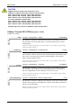
Related Documents
≡≡≡≡≡≡≡≡≡≡≡≡≡≡≡≡≡≡≡≡≡≡≡≡≡
Type
DTSC-200 Series
DTSC-200 - Installation
DTSC-200 - Configuration
DTSC-200 - Operation
DTSC-200 - Application
DTSC-200 - Interfaces
Additional Manuals
IKD 1 - Manual
this manual
English
German
37385
37386
37387
37388
37389
-
37135
GR37135
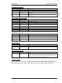
Discrete expansion board with 8 discrete inputs and 8 relay outputs that can be coupled via the CAN bus to the control unit. Evaluation of the discrete inputs as well as control of the relay outputs is done via the control unit.
LeoPC1 - User Manual
37146
GR37146
PC program for visualization, configuration, remote control, data logging, language upload, alarm and user management, and management of the event recorder. This manual describes the set up of the program and interfacing with the control unit.
LeoPC1 - Engineering Manual
37164
GR37164
PC program for visualization, configuration, remote control, data logging, language upload, alarm and user management, and management of the event recorder. This manual describes the configuration and customization of the program.
Table 1-1: Manual - overview
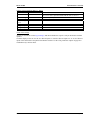
Intended Use The unit must only be operated in the manner described by this manual. The prerequisite for a
proper and safe operation of the product is correct transportation, storage, and installation as well as careful operation and maintenance.
NOTE
This manual has been developed for a unit fitted with all available options. Inputs/outputs, functions,
configuration screens, and other details described, which do not exist on your unit, may be ignored.
The present manual has been prepared to enable the installation and commissioning of the unit. Due to
the large variety of parameter settings, it is not possible to cover every combination. The manual is
therefore only a guide. In case of incorrect entries or a total loss of functions, the default settings may
be taken from the list of parameters enclosed in the configuration manual 37386.
Page 6/97
© Woodward
Manual 37389A
DTSC-200 Series - Interfaces
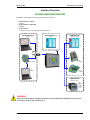
Interface Overview
≡≡≡≡≡≡≡≡≡≡≡≡≡≡≡≡≡≡≡≡≡≡≡≡≡
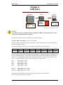
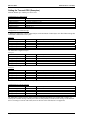
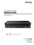
The DTSC-200 provides the following communication interfaces:
• Serial interface 1 (DPC)
LeoPC1
• Serial interface 2 (RS-485)
Modbus
• CAN interface
CANopen or CAN CAL (dependent on application)
Serial interface 1
Serial interface 2
CAN interface
RS-232
RS-485
CANopen protocol
PLC
Modbus RTU Slave
LeoPC1 protocol
DPC
IKD 1
IO module
Modem (RS-232)
PC
Modem
Phoenix
IO module
CAN interface
CAN CAL protocol
GW 4
Gateway to
- LeoPC1
- Profibus
(PLC)
Figure 1-1: Interface overview
WARNING
When connecting the direct configuration interface, the Woodward DPC with RJ45 connector must be
used. Failure to do so may destroy the unit.
© Woodward
Page 7/97
Manual 37389A
DTSC-200 Series - Interfaces
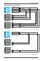
Modbus Half/Full Duplex Application
RS-485 A (TxD-)
RS-485 B (TxD+)
RS-485 A’ (RxD-)
RS-485 B’ (RxD+)
R=120 Ohms
R=120 Ohms
PLC (Master)
5
6
7
8
DTSC (Slave 1)
5
6
7
8
R=120 Ohms
R=120 Ohms
DTSC (Slave 2)
Figure 1-2: Interface overview - serial interface Modbus full-duplex
RS-485 A (TxD-)
RS-485 B (TxD+)
R=120 Ohms
PLC (Master)
7
8
DTSC (Slave 1)
7
8
R=120 Ohms
DTSC (Slave 2)
Figure 1-3: Interface overview - serial interface Modbus half-duplex
Page 8/97
© Woodward
Manual 37389A
DTSC-200 Series - Interfaces
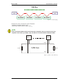
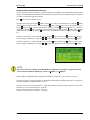
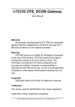
CAN Bus
≡≡≡≡≡≡≡≡≡≡≡≡≡≡≡≡≡≡≡≡≡≡≡≡≡
Terminantion
resistor
Terminantion
resistor
Bus line
Bus line
Bus line
Bus line
Figure 1-4: CAN bus topology
Characteristics of the CAN interface used by Woodward:
• Standard: Compatible with ISO 11898
• Electrically isolated: Isolation voltage 1,500 VDC
NOTE
Please note that the CAN bus must be terminated with an impedance which corresponds to the wave
impedance of the cable (e.g. 120 Ohm, ¼ W). The CAN bus is terminated between CAN-H and CAN-L.
Node 30
Node 1
CAN_H
120 Ohm
CAN bus
120 Ohm
CAN_L
Figure 1-5: Interface - The CAN bus loop
© Woodward
Page 9/97
Manual 37389A
DTSC-200 Series - Interfaces
Chapter 2.
Data Telegrams
Interface Monitoring
≡≡≡≡≡≡≡≡≡≡≡≡≡≡≡≡≡≡≡≡≡≡≡≡≡
It is possible to monitor the CAN interface for received data of an external I/O board. Refer to the configuration
manual for more information about this monitoring function.
Transmit Telegram
≡≡≡≡≡≡≡≡≡≡≡≡≡≡≡≡≡≡≡≡≡≡≡≡≡
The transmit telegram provides all measuring and status data of the DTSC. The data have different addresses and
will be transmitted in the respective format depending on the selected interface.
Modbus
Data transmission in Modbus format is performed in the order of the transmit telegram (refer to Appendix A:
Transmission Telegram on page 43). The data addresses may be taken from the respective column of the transmit
telegram.
CAN (CAL)
The DTSC sends its data via cyclic CAN messages. If a GW 4 is used, the baud rate must be configured to
125 kBaud.
NOTE
Instead of using a GW 4, a CAN to USB (or RS-232) converter may be used.
CANopen
Using the mapped objects, which are described in detail starting on page 25, enables you to send data by setting
the object ID 2C76h on the basis of the CANopen protocol.
This document contains tables of further mapped objects, which may be configured. Refer to Appendix A:
Transmission Telegram on page 43.
NOTE
When using the mapped objects listed in the appendix instead of the complete transmit telegram, the
refresh rate of the messages may be reduced.
Page 10/97
© Woodward
Manual 37389A
DTSC-200 Series - Interfaces
Receive Telegram
≡≡≡≡≡≡≡≡≡≡≡≡≡≡≡≡≡≡≡≡≡≡≡≡≡
The receive telegram enables to acknowledge alarm messages, which are no longer active, via remote control
In order to execute the desired command, a rise of the pulse of the respective signal from Low to High is required.
An acknowledgement command must be sent twice. The first rise of the pulse resets the horn. The second rise of
the pulse acknowledges the unit, if the fault is not present anymore.
NOTE
Please note that the respective remote control parameters must be configured in the LogicsManager of
the unit. Refer to the application manual 37388 for more detailed information about this.
Modbus
It is possible to remote control the DTSC using the bits 2 to 4 of control word 1 on address 503. The Remote
Control Telegram in Appendix A on page 71 is valid for both, CANopen as well as Modbus, and indicates the arrangement of the remote control bits.
© Woodward
Page 11/97
Manual 37389A
DTSC-200 Series - Interfaces
CAN (CAL)
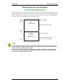
The Woodward LeoPC1 software may be used to remote control the DTSC via a connected PC. After selecting
the desired remote control command, the remote control command must be confirmed by selecting the "Set" button.
Figure 2-1: Data telegrams - remote control via CAN
NOTE
The control words "Remote stop" and "Remote start" have no effect on the DTSC-200.
CANopen
It is possible to remote control the DTSC using the bits 2 to 4 of control word 1 on address 503. The Remote
Control Telegram in Appendix A on page 71 is valid for both, CANopen as well as Modbus, and indicates the arrangement of the remote control bits.
Page 12/97
© Woodward
Manual 37389A
DTSC-200 Series - Interfaces
Chapter 3.
Serial Interface
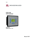
Overview
≡≡≡≡≡≡≡≡≡≡≡≡≡≡≡≡≡≡≡≡≡≡≡≡≡
PLC RS-232 port
Serial 1
via DPC
Serial 2
PLC RS-485 port
Modem RS-232 port
PC RS-232 port
LeoPC1
Figure3-1: Serial interface - overview
© Woodward
Page 13/97
Manual 37389A
DTSC-200 Series - Interfaces
Modbus RTU Slave
≡≡≡≡≡≡≡≡≡≡≡≡≡≡≡≡≡≡≡≡≡≡≡≡≡
General Information
Modbus is a serial communications protocol published by Modicon in 1979 for use with its programmable logic
controllers (PLCs). It has become a de facto standard communications protocol in industry, and is now the most
commonly available means of connecting industrial electronic devices. The DTSC supports a Modbus RTU
Slave module. This means that a Master node needs to poll the DTSC slave node. Modbus RTU can also be multi-dropped, or in other words, multiple Slave devices can exist on one Modbus RTU network, assuming that the
serial interface is a RS-485. Detailed Information about the Modbus protocol are available on the following website:
http://www.modbus.org/specs.php
There are also various tools available on the internet. We recommend to use ModScan32 which is a Windows
application designed to operate as a Modbus Master device for accessing data points in a connected Modbus
Slave device. It is designed primarily as a testing device for verification of correct protocol operation in new or
existing systems. It is possible to download a trial version from the following website:
http://www.win-tech.com/html/modscan32.htm
DE
EN
Configuration
Baudrate
Baudrate
3170
EN
2.4 / 4.8 / 9.6 / 14.4 / 19.2 / 38.4 / 56 / 115 kBaud
This parameter defines the baud rate for communications. Please note, that all
participants on the service interface must use the same baud rate.
CL2
DE
Serial interface 2: Baud rate
Parity
Parity
Serial interface 2: Parity
no / even / odd
The used parity of the service interface is set here.
CL2
DE
EN
3171
Stop bits
Stop Bits
Serial interface 2: Stop bits
one / two
The number of stop bits is set here.
CL2
EN
3172
Serial interface 2: Full-/halfduplex mode
Fullduplex / Halfduplex
DE
Full-, halfduplex mode
Voll-, Halbduplex Modus
CL2
DE
EN
3173
ModBus Slave ID
ModBus Slave ID
CL2
EN
3185
Serial interface: Modbus Slave ID
0 to 255
The Modbus device address is entered here, which is used to identify the device
via Modbus. If 0 is entered here, the Modbus Slave module is disabled.
Serial interface: Reply delay time
0,00 to 1,00 s
DE
Modbus Reply delay time
Modbus Zeitverzöger. der Antwort
CL2
Fullduplex ... Fullduplex mode is enabled.
Halfduplex... Halfduplex mode is enabled.
3186
Page 14/97
This is the minimum delay time between a request from the Modbus master and
the sent response of the slave. This time is also required if an external interface
converter to RS-485 is used for example. Please note that you also need the
DPC in this case.
© Woodward
Manual 37389A
DTSC-200 Series - Interfaces
Modbus Addressing and Data Model
≡≡≡≡≡≡≡≡≡≡≡≡≡≡≡≡≡≡≡≡≡≡≡≡≡
The DTSC Modbus slave module distinguishes between visualization data and configuration & remote control
data. The different data is accessible over a split address range and may be read via the "Read Holding Register"
function. Furthermore, DTSC parameters and remote control data can be written with the "Preset Single Registers" function or "Preset Multiple Registers" (refer to figure below).
Modbus commands:
Modicon
address
DTSC
visualization data
Read Holding Register (0x03)
450001
450000
DTSC
remote control
&
configuration data
Read Holding (0x03)
Preset Multiple Registers (0x10)
Preset Single Register (0x06)
40001
NOTE
All addresses in this document comply with the Modicon address convention. Some PLCs or PC programs use different address conventions depending on their implementation. Then the address must
be increased and the leading 4 may be omitted.
Please refer to your PLC or program manual for more information. This determines the address sent
over the bus in the Modbus telegram. The Modbus starting address 450001 of the visualization data
may become bus address 50000 for example.
© Woodward
Page 15/97
Manual 37389A
DTSC-200 Series - Interfaces
Visualization
≡≡≡≡≡≡≡≡≡≡≡≡≡≡≡≡≡≡≡≡≡≡≡≡≡
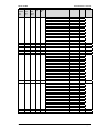
The visualization over Modbus is provided in a very fast data protocol where important system data like alarm
states, AC measurement data, switch states and various other information may be polled. According to the DTSC
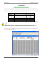
Modbus addressing range, the visualization protocol can be reached on addresses starting at 450001. On this address range it is possible to do block reads from 1 up to 128 Modbus registers at a time.
Modbus Read
Addresses
450001
450002
............
............
............
............
450088
Description
Multiplier
Units
Protocol-ID
Source 2: Voltage VL12
.........
.........
.........
.........
Timer state feedback signals
0.1
.....
.....
.....
.....
-
-V
.....
.....
.....
.....
-
Table 3-1: Modbus - address range block read
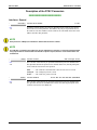
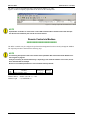
NOTE
Table 3-1 is only an excerpt of the data protocol. It conforms to the data protocol, that is also used by
CAN bus. Refer to Appendix A: Transmission Telegram on page 43 for the complete protocol.
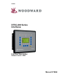
The following exemplary ModScan32 screenshot shows the configurations made to read the visualization protocol with a block read of 128 registers.
Figure 3-2: Modbus - visualization configurations
Page 16/97
© Woodward
Manual 37389A
DTSC-200 Series - Interfaces
Configuration
≡≡≡≡≡≡≡≡≡≡≡≡≡≡≡≡≡≡≡≡≡≡≡≡≡
The Modbus interface can be used to read/write parameters of the DTSC. According to the DTSC Modbus addressing range for the configuration addresses, the range starts at 40001 and ends at 450000. You can always
access only one parameter of the system in this address range. The Modbus address can be calculated depending
on the parameter ID as illustrated below:
Modbus address =
Parameter ID < 10000
40000 + (Par. ID+1)
Parameter ID >= 10000
400000 + (Par. ID+1)
Table 3-2: Modbus - address calculation
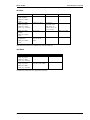
Block reads in this address range depend on the data type of the parameter. This makes it important to set the correct length in Modbus registers which depends on the data type (UNSIGNED 8, INTEGER 16, etc.). Refer to
Table 3-3 for more information.
DTSC types
UNSIGNED 8
UNSIGNED 16
INTEGER 16
UNSIGNED 32
INTEGER 32
LOGMAN
TEXT/X
Modbus
registers
1
1
1
2
2
7
X/2
Table 3-3: Modbus - data types
NOTE
The parameters of the following examples are an excerpt of the parameter list in the appendix of the
Configuration Manual 37386. Please refer to this manual for the complete parameter list.
NOTE
Be sure to enter the password for code level 2 or higher for the corresponding interface to get access
for changing parameter settings.
NOTE
The new entered value must comply with the parameter setting range when changing the parameter
setting.
© Woodward
Page 17/97
Manual 37389A
DTSC-200 Series - Interfaces
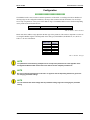
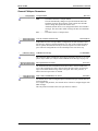
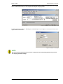
Example 1: Addressing the password for the CAN interface:
Par.
ID.
10402
Parameter
Password for CAN interface1
Setting range
Data type
0000 to 9999
UNSIGNED 16
Modbus address = 400000 + (Par. ID +1) = 410403
Modbus length = 1 (UNSIGNED 16)
The following Modscan32 screenshot shows the configurations made to address parameter 10402.
Figure 3-3: Modbus - configuration example 1
Example 2: Addressing the rated voltage of source 1:
Par.
ID.
1774
Parameter
Rated voltage S1
Setting range
Data type
50 to 650000 V
UNSIGNED 32
Modbus address = 40000 + (Par. ID +1) = 41775
Modbus length = 2 (UNSIGNED 32)
The following Modscan32 screenshot shows the configurations made to address parameter 1774.
Figure 3-4: Modbus - configuration example 2
Page 18/97
© Woodward
Manual 37389A
DTSC-200 Series - Interfaces
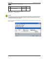
Example 3: Addressing source 2 voltage measuring:
Par.
ID.
1861
Parameter
S2 voltage measuring
Setting range
Data type
3Ph 4W {0}
3Ph 3W {1}
1Ph 2W {2}
1Ph 3W {3}
UNSIGNED 16
Modbus address = 40000 + (Par. ID +1) = 41862
Modbus length = 1 (UNSIGNED 16)
NOTE
If the setting range contains a list of parameter settings like in this example, the parameter settings are
numbered and start with 0 for the first parameter setting. The number corresponding with the respective parameter setting must be configured.
The following Modscan32 screenshot shows the configurations made to address parameter 1861, which is configured to "3Ph 4W".
Figure 3-5: Modbus - configuration example 3
© Woodward
Page 19/97
Manual 37389A
DTSC-200 Series - Interfaces
Exception Responses
≡≡≡≡≡≡≡≡≡≡≡≡≡≡≡≡≡≡≡≡≡≡≡≡≡
The DTSC Modbus interface has multiple exception responses to show that a request could not be executed. Exception responses can be recognized if the response telegram contains the request function code with an offset
of 128 (0x80 hex).
Table 3-4 explains possible reasons for an exception response that occurred.
DTSC Modbus
Exception Responses
Code
01
Name
ILLEGAL FUNCTION
02
ILLEGAL ADDRESS
•
•
03
ILLEGAL DATA VALUE
•
•
•
Reason
The sent request function code is not supported by the DTSC
Modbus interface.
Permission to read/write the parameter is denied.
The amount of requested registers is wrong to read/write this registers.
The data value exceeds the min. and max. limitations of the parameter upon a write request.
There is no parameter on the requested address.
Table 3-4: Modbus - exception responses
Page 20/97
© Woodward
Manual 37389A
DTSC-200 Series - Interfaces
Chapter 4.
CAN (CAL)
DTSC 200
-
Baudrate :
Transmit -ID
Protocol type
Expand block 1
CAN :
CAN Protocol
Baudrate :
LeoPC1
GW 4
125kBd
831
3
YES
Baudrate : 9600Bd
Device : Gateway
RS-232
LeoPC1
125kBd
Figure 4-1: CAN (CAL) interface - overview
NOTE
The transmission rate is configurable (default: 125 kBaud). If a GW 4 is used for data transfer, a transmission rate of 125 kBaud must be configured.
The CAN ID, on which the DTSC is transmitting is calculated as follows:
CAN-ID = d‘800 + Item number (or H‘320 + item number)
(The item number is an adjustable parameter in the DTSC, which directly influences the CAN ID that the unit
sends the visualization message).
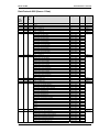
A visualization message which is send out of an DTSC has got 8 Byte and is built as follows:
Byte 0
H‘DD
Byte 1
MUX
number
Byte 2
Data word 1
High-Byte
Byte 3
Data word 1
Low Byte
Byte 4
Data word 2
High-Byte
Byte 5
Data word 2
Low Byte
Byte 6
Data word 3
High-Byte
Byte 7
Data word 3
Low Byte
The byte 0 is always used to show the hexadecimal value H'DD in a visualization message. This defines the message as a visualization message. As the complete transmission telegram of the DTSC includes more than three
words byte 1 sends additionally a MUX number starting with 0. Therefore it is theoretically possible to send
(256 × 3 = 768) words via the CAN ID. The whole telegram is built up as follows:
line 1:
line 2:
line 3:
line 4:
line 5:
.
line (n):
line (n+1):
line (n+2):
MUX number 0, word 1
MUX number 0, word 2
MUX number 0, word 3
MUX number 1, word 1
MUX number 1, word 2
MUX number (n-1/3), word 1
MUX number (n-1/2), word 2
MUX number (n-1/1), word 3
(n) depends on the total length of the unit special telegram and can not be larger than H’FF.
Refer to Appendix A for the interface telegram.
© Woodward
Page 21/97
Manual 37389A
DTSC-200 Series - Interfaces
Chapter 5.
CANopen
Introduction
≡≡≡≡≡≡≡≡≡≡≡≡≡≡≡≡≡≡≡≡≡≡≡≡≡
Extract from: Controller Area Network; Basics, Protocols, Chips and Applications; By Prof. Dr.-Ing. K. Etschberger; ISBN: 3-00-007376-0;
also see IXXAT GmbH (http://www.ixxat.de)
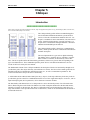
The CANopen family profile defines a standardized application for distributed industrial automation systems based on
CAN as well as the communication standard CAN CAL. CANopen is a standard of CAN-in-Automation (CiA) that after its
release, found a broad acceptance, especially in Europe. CANopen can be considered the leading standard for CAN based
industrial and embedded system solutions.
The CANopen family profile is based on a "Communication
Profile", which specifies the basic communication mechanisms
and their description.
The most important device types such as digital and analog
I/O modules, drives, operating devices, controllers, programmable controls or encoders, are described by "Device Profiles". The device profiles define the functionality, parameters, and access to process data corresponding to the
types of standard devices. These standardized profiles permit devices from different manufacturers to be accessed via the bus in exactly the same manner.
The fundamental element of the CANopen standard is the description of the device functionality through an object dictionary (OD). The object dictionary is divided into two sections. The first section contains general device
information like device identification, manufacturer name, etc., as well as communication parameters. The
second section describes the specific device functionality.
A 16-Bit index and an 8-Bit sub-index identify the entry ("object") in the object dictionary. Each entry in the object dictionary provide a basis for a standardized network access to the "Application Objects" of a device, such as
input and output signals, device parameters, device functions or network variables.
The functionality and characteristics of a CANopen device can be described by means of an "Electronic Data
Sheet" (EDS) using the ASCII-format. The EDS acts as a kind of template that describes the data and features,
which are accessible via the network. The "Device Configuration File" (DCF) describes the actual device settings. EDS and DCF can be provided in the form of a data carrier, which can be downloaded from the Internet or
stored inside the device.
Page 22/97
© Woodward
Manual 37389A
DTSC-200 Series - Interfaces
Similar to other well-known field bus systems CANopen also distinguishes two basic data transfer mechanisms:
The high-speed exchange of small process data portions through "Process Data Objects (PDO)" as well as the
access to entries in the object dictionary through "Service Data Objects (SDO)". The latter ones are primarily
used for the transmission of parameters during the device configuration as well as in general for the transmission
of larger data portions. Process data object transmissions are generally event triggered, cyclic or requested as
broadcast objects without the additional protocol overhead. A PDO can be used for the transmission of a maximum of 8 data bytes. In connection with a synchronization message, the transmission as well as the acceptance of
PDOs can be synchronized through the entire network ("Synchronous PDOs"). The assignment of application
objects to a PDO (Transmission Object) is adjustable through a structure description ("PDO Mapping") which is
stored in the object dictionary, thus allowing the adjustment of a device to the corresponding application requirements.
The transmission of SDOs is performed as a confirmed data transfer with two CAN objects in form of a peer-topeer connection between two network nodes. The addressing of the corresponding object dictionary entries is accomplished by specifying the index and the sub-index of the entry. Transmitted messages can be unlimited in
length. The transmission of SDO messages involves an additional protocol overhead.
Standardized event-triggered "Emergency Messages" of high priority are reserved to report device malfunctions.
A common system time can be provided through a central timing message (not included yet).
Management functionality like controlling and monitoring the communication status of the nodes is accomplished by a network management protocol (NMT) organized according to a logical master-slave relationship.
Two alternative mechanisms ("Node-Guarding" and "Heartbeat-messages") are available to implement nodemonitoring functionality.
The assignment of CAN message identifiers to PDOs and SDOs is possible by direct modifications of entries inside the data structure of the object dictionary or, for simple system structures, through the use of pre-defined
identifiers.
Server Data Objects (SDO) - Communication
As already mentioned in the introduction, each CANopen device has an object directory.
All parameters, status variables, measurement values, and input values of the device are stored in this object directory. These parameters are called objects in the CANopen protocol description.
The single objects may contain up to 254 values. If an object has more than one value, these contain a sub-index.
Example: Object 1017h with One Value
Name of the object: Producer Heartbeat Time
Contains a value, which may be read and written.
Example: Object 1200h with Several Values
Name of the object: Server SDO parameter
Sub-index 0 contains the number of sub-indices.
Sub-index 1 contains the COB-ID Client -> Server (rx)
Sub-index 2 contains the COB-ID Server -> Client (tx)
Reading out and changing these objects is performed using an SDO.
This data exchange will be implemented using at least two CAN telegrams, where each on is using an own CAN
identifier.
The CAN identifiers of the default service data object are fixed in the object 1200h and are changed using the
Node ID.
The values are:
CAN identifier for the reception (Client -> Server): Node ID + 1536 (600h)
CAN identifier for the reply (Server -> Client): Node ID + 1408 (580h)
© Woodward
Page 23/97
Manual 37389A
DTSC-200 Series - Interfaces
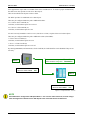
Some applications require that several SDO clients access one SDO server. To ensure a proper communication,
the SDO server must provide several service data objects.
These are described in the objects 1201h to 127Fh.
The DTSC provides five additional service data objects.
These may be configured under the point "Additional S-SDO".
2 to 5 Client->Server COP-ID (tx)
CAN-IDs, on which SDO requests are received.
2 to 5 Server->Client COP-ID (rx)
CAN-IDs, on which SDO replies are sent.
If a unit is not only intended to work as a server, but also as a client, it requires client service data objects.
These may be configured under the point "Additional C-SDO (client SDO)".
1. Client->Server COP-ID (rx)
CAN-IDs, on which SDO requests are sent.
1. Server -> Client COP-ID (tx)
CAN-IDs, on which SDO replies are received.
By entering 80000000h (2147483648 dec) for the CAN ID, the CAN identifiers can be disabled if they are not
necessary.
Client Server: configurable Master / Slave
Server Client: configurable Connection
Master 1
Device number: 1
1.Client Server COB-ID:
1.Server Client COB-ID:
free
free
Slave 2
PLC
1.Client Server COB-ID:
1.Server Client COB-ID:
free
free
Figure 5-1: CANopen interface - overview
NOTE
If the DTSC-200 is configured to CAN-Open Master = "Yes" and one external terminal, it sends configuration messages to the default service data objects to the connected terminal as SDO client.
Page 24/97
© Woodward
Manual 37389A
DTSC-200 Series - Interfaces
Process Data Objects (PDO)
Process data objects are used to transmit real-time data. No, one, or several recipients are possible with this.
Process data objects may be sent cyclically or continuously (other transmission types are not supported by the
DTSC), this is configured using the parameter "Transmission Type".
The values 254 and 255 define an asynchronous transmission.
In case of the asynchronous transmission, the PDOs are sent after a certain time. This will be configured using
the event timer.
The values 1 to 240 are used for a synchronous transmission. The PDO will be sent as a response to a received
SYNC message here. If the value is configured to 1, the PDO will be sent for every received SYNC message, if
the value is configured to 2, the PDO will only be sent for every 2nd SYNC message, and so on.
No PDOs will be sent for the remaining values.
Data in the PDO
The data, which is transmitted with the PDO, is to be configured at the unit. The parameters "Mapped Object" are
provided for this.
The parameter "Number of Mapped Objects" is used to configure the number of mapped objects.
Then, up to four objects may be entered, whose data is to be transmitted. The identifiers of the objects may be
found in the operating instructions.
© Woodward
Page 25/97
Manual 37389A
DTSC-200 Series - Interfaces
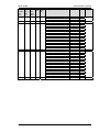
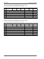
Setting the Transmit PDO (Examples)
With the TPDOs up to 8 data bytes can be send.
Configuration of a data protocol
Parameter
Number of mapped objects
1. Mapped Object
2. Mapped Object
3. Mapped Object
4. Mapped Object
Value
Parameter no. 1 to 4
for example parameter no. 3191
Parameter no. 0
Parameter no. 0
Parameter no. 0
Configuration of a TPDO message
A TPDO can contain one or more mapped objects with a maximum of 4 data bytes each. The TDPO message has
a maximum combined total of 8 bytes.
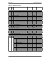
Example 1
Parameter
Number of mapped objects
1. Mapped Object
2. Mapped Object
3. Mapped Object
4. Mapped Object
Value
Parameter no. 2
Parameter no. 108
Parameter no. 160
Parameter no. 0
Parameter no. 0
Number of bytes
unsigned32 -> 4byte
unsigned16 -> 2byte – total 6 bytes
The TPDO has a length of 6 bytes.
Example 2:
Parameter
Number of mapped objects
1. Mapped Object
2. Mapped Object
3. Mapped Object
4. Mapped Object
Value
Parameter no. 2
Parameter no. 108
Parameter no. 109
Parameter no. 0
Parameter no. 0
Number of bytes
unsigned32 -> 4Byte
unsigned32 -> 4Byte – total 8 bytes
The TPDO has a length of 8 bytes.
Example 3:
Parameter
Number of mapped objects
1. Mapped Object
2. Mapped Object
3. Mapped Object
4. Mapped Object
Value
Parameter no. 3
Parameter no. 108
Parameter no. 109
Parameter no. 110
Parameter no. 0
Number of bytes
unsigned32 -> 4byte
unsigned32 -> 4byte – total 8 bytes
unsigned32 -> 4byte – total 12 bytes !FAULT!
The TPDO has a length of 12 bytes, as only 8 bytes are admissible, an idle TPDO is sent.
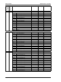
Configuration of a SYNC message
Parameter
Number of mapped objects
1. Mapped Object
2. Mapped Object
3. Mapped Object
4. Mapped Object
Value
Parameter no. 0
Parameter no. 0
Parameter no. 0
Parameter no. 0
Parameter no. 0
Number of bytes
The TPDO has a length of 0 bytes. If the COP ID is configured accordingly for example 80h = 128dez, it is
working like a SYNC message. Thereby the DTSC has the possibility to send a SYNC message to the attached
devices to arrange a reaction with a PDO, however the time of the transmission is not appraised.
Page 26/97
© Woodward
Manual 37389A
DTSC-200 Series - Interfaces
SYNC Message
The SYNC message is a CAN message without data. The CAN ID on which the DTSC sends appropriately configured PDOs, is configured with the parameter "COB-ID SYNC Message".
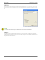
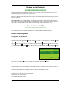
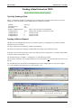
Using a CANopen Configuration Program
If the DTSC is used as a single unit, the default settings provide useful operation possibilities already. If the
DTSC is used together with other CANopen devices, a detailed configuration will be necessary.
An *.eds file is enclosed with the unit for this purpose. An example of this file being used with the CANopen
Configuration Studio of IXXAT is shown in the following.
Please refer to IXXAT for a more detailed explanation about this tool.
Figure 5-2: CANopen interface - CANopen configuration software
The DTSC parameters may be changed after loading the *.eds file. The values are only overwritten by the DTSC
if the correct password has been entered prior to attempting to make any changes; otherwise, a fault message will
be issued, which states that the parameter may not be overwritten.
The configuration of the mapped objects of a send PDO is very clear and easy with this program.
Configuration of the transmission type:
The following transmission types are supported:
• "asynchronous (Profile Event)" and "asynchronous (Manuf. Event)" – both send a message after the
event timer has expired
• "synchronous cyclic" with the according transmission rate
© Woodward
Page 27/97
Manual 37389A
DTSC-200 Series - Interfaces
Settings for Connection with External Devices
≡≡≡≡≡≡≡≡≡≡≡≡≡≡≡≡≡≡≡≡≡≡≡≡≡≡≡≡≡≡≡≡≡≡≡≡≡≡≡
Name
Device number
Protocol
Baudrate
Description
Determines the node ID for CANopen
Determines the protocol – select this for CANopen
Determines the baud rate
NOTE
The standard values of the DTSC enable to connect devices on the basis of the CANopen protocol
quickly and easily.
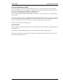
Figure 5-3 shows an overview of the different device combinations, which are possible:
PLC
1st IKD 1
extension card
8 DIs
8 DOs
2nd IKD 1
extension card
8 DIs
8 DOs
Phoenix
extension card
16 DIs
16 DOs
Figure 5-3: CANopen interface - external devices
PLC:
IKD 1:
Phoenix extension card:
PLC of the plant
2 extension cards, each for 8 additional external inputs and outputs
Extension card for 16 additional external inputs and outputs
NOTE
The parameters, which are highlighted red in the following figures, must be observed particularly, because these are essential for a communication with the respective device and may differ the default
values.
CAUTION
The ID settings are entered in hexadecimal format in the DTSC and are therefore listed in decimal and
hexadecimal format in the following tables.
Page 28/97
© Woodward
Manual 37389A
DTSC-200 Series - Interfaces
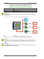
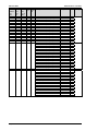
Expansion with One IKD 1 (8 Additional External DI/DO)
CANopen
1st IKD 1
extension card
Receive PDO1 :
RPDO1 function :
COB ID :
1st IKD
513
CAN N ode ID:
CAN ID receive data :
CAN ID send data :
Physical state only:
0
385
513
Yes
Transmit PDO1 :
COB ID :
Transmission Type:
Event Timer:
Number mapp . objects:
1. Mapped object :
2./3./4. Mapped object :
385
255
20 ms
4
8001
8000
Figure 5-4: CANopen Schnittstelle - Einstellungen für externe Geräte
Configuration of the receive PDO 1
Parameter
Value
COB-ID
201h = 513 Dec
Function
1. IKD
Node-ID of the de- 2
vice
RPDO-COB-ID
282h = 642 Dec
ext. device 1
Comment
CAN-ID on which the data are received
The data received on the COB-ID were assigned to the external DI 1 to DI 8
The IKD is not configured by the DTSC; the suggested value is therefore a
default value.
The IKD is not configured by the DTSC; the suggested value is therefore a
default value.
Configuration of transmit PDO (e.g. PDO1)
Parameter
COB-ID
Transmission type
Event-timer
Number of mapped
objects
1. Mapped Object
2. Mapped Object
3. Mapped Object
4. Mapped Object
Value
181h = 385 Dec
FFh = 255 Dec
20
4
Comments
CAN-ID on which the data was sent
The PDO is sent circular
The PDO is sent every 20 ms
Parameter no. 8001
Parameter no. 8000
Parameter no. 8000
Parameter no. 8000
DI 1 to 8 is issued
Settings at the IKD
Parameter
Node-ID
CAN-ID transmitting data
© Woodward
Value
0
201h = 513 Dec
Comments
So that the entries of the CAN IDs are taken over
The DTSC receives on this ID.
Page 29/97
Manual 37389A
DTSC-200 Series - Interfaces
Settings for DIs on IKD
Parameter
Physical state
Value
YES
Comments
Only the physical state of the inputs is transmitted. (The settings under idle
current, tripping delay, revert delay, enabling, self-resetting and acknowledge
input are without effect). These settings have to be selected for devices, which
include these parameters (e.g. the DTSC-200).
Check of the settings
Actuate an external DO via the LogicsManager and check whether the respective relay at the IKD operates.
Scroll the display screens to view the ext. discrete inputs 1 to 8. A set of discrete inputs will be shown that correspond to the IKD. Use the "FAQ CAN Bus" chapter on page 40 to troubleshoot any CAN bus faults.
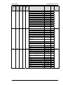
Expansion with Two IKD 1 (16 Additional External DI/DO)
The first IKD will be adjusted like described above. For the second IKD the following settings must be configured.
CAN Open
Receive PDO1 :
RPDO1 function :
COB ID :
1st IKD
513
1st IKD 1
Receive PDO2 :
RPDO2 function :
COB ID :
extension card
2st IKD
514
Transmit PDO1 :
COB ID :
Transmission Type:
Event Timer:
Number mapp . objects:
1. Mapped object :
2./3./4. Mapped object :
385
255
20 ms
4
8001
8000
Transmit PDO2 :
COB ID :
Transmission Type:
Event Timer:
Number mapp . objects:
1. Mapped object :
2./3./4. Mapped object :
386
255
20 ms
4
8002
8000
CAN N ode ID:
CAN ID receive data :
CAN ID send data :
Physical state only:
0
385
513
Yes
2nd IKD 1
extension card
CAN N ode ID:
CAN ID receive data :
CAN ID send data :
Physical state only:
0
386
514
Yes
Figure 5-5: CANopen interface - expansion with two IKD 1
Page 30/97
© Woodward
Manual 37389A
DTSC-200 Series - Interfaces
Setting of the receive PDO 2
Parameter
COB-ID
Function
Node-ID of the
device
RPDO-COB-ID
ext. device 1
Value
202h = 514 Dec
2. IKD
3
283h = 643 Dec
Comments
CAN-ID on which the data are received
The data received on the COB-ID were assigned to the external DI 9 to DI 16
The IKD is not configured by the DTSC; the suggested value is therefore a
default value.
The IKD is not configured by the DTSC; the suggested value is therefore a
default value.
Settings of transmit PDO (e.g. PDO 2)
Parameter
COB-ID
Transmission type
Event-timer
Number of mapped
objects
1. Mapped Object
2. Mapped Object
3. Mapped Object
4. Mapped Object
Value
182h = 386 Dec
FFh = 255 Dec
20
4
Comments
CAN-ID on which the data was sent
The PDO is sent circular
The PDO is sent every 20 ms
Parameter no. 8002
Parameter no. 8000
Parameter no. 8000
Parameter no. 8000
DI 9 to 16 is issued
Settings of DIs on IKD 1 #2
Parameter
Node-ID
CAN-ID receiving
data
Relay 1 as ready
for operation
Value
0
182h = 386 Dec
Comments
That the entries of CAN-IDs are accepted
DTSC receives on this ID
NO
Otherwise the DTSC cannot be controlled correctly.
Settings on IKD 1 #2
Parameter
Node-ID
CAN-ID transmitting data
Value
0
202h = 514 Dec
Comments
So that the entries of the CAN IDs are taken over
The DTSC receives on this ID.
Settings for DIs on IKD 1 #2
Parameter
Physical state
Value
YES
Comments
Only the physical state of the inputs is transmitted. (The settings under idle
current, tripping delay, revert delay, enabling, self-resetting and acknowledgeinput are without effect). These settings have to be selected for devices,
which include these parameters (e.g. the DTSC-200).
Check of the settings
Actuate an external DO via the LogicsManager and check whether the respective relay at the IKD operates.
Scroll the display screens to view the ext. discrete inputs 9 to 16. A set of discrete inputs will be shown that correspond to the IKD. Use the "FAQ CAN Bus" chapter on page 40 to troubleshoot any CAN bus faults.
© Woodward
Page 31/97
Manual 37389A
DTSC-200 Series - Interfaces
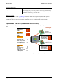
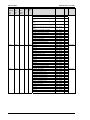
Expansion with the Phoenix terminal IL CAN BK / ILB CO 24 16DI 16DO (16
DI/DO)
The specified settings are valid for a Phoenix terminal with Node ID 2.
CAN Open
Phoenix
extension card
Node ID :
Receive PDO1 :
RPDO1 function :
COB ID :
Node ID:
COB ID ext. :
2
Phoenix
513
2
385
Transmit PDO1 :
COB ID :
Transmission Type:
Event Timer:
Number mapp . objects:
1. Mapped object :
2./3./4. Mapped object :
385
255
20 ms
4
8003
8000
Figure 5-6: CANopen interface - expansion with Phoenix terminal
Parameter
CAN-open Master
Max time for reply ext. devices
Time for re-init ext. devices
Value
YES
1.0
100
Comments
If this time is set 0, the attached Phoenix terminal may not be
configured correctly.
Setting of the receiving PDO 1
Parameter
Value
COB-ID
201h = 513 Dec
Function
BK16DIDO
Node-ID of the de- 2
vice
RPDO-COB-ID
181h = 385 Dec
ext. device 1
Note
CAN-ID to receive data
The received data (via the COB-ID) are copied to the ext. DI 1 to 16
According to the setting of the terminals
The Phoenix terminal must be configured in that way that it can receive a
PDO on that COB-ID
CAUTION
The 2nd PDO this function must be configured to OFF.
NOTE
The DTSC is the CANopen master.
Page 32/97
© Woodward
Manual 37389A
DTSC-200 Series - Interfaces
Settings of the transmitting PDO (i.e. PDO3)
Parameter
COB-ID
Value
381h = 385 Dec
Transmission type
Event-timer
Number of mapped
objects
1. Mapped Object
2. Mapped Object
3. Mapped Object
4. Mapped Object
FFh = 255 Dec
20
1
Parameter no. 8003
Parameter no. 0
Parameter no. 0
Parameter no. 0
Note
CAN-ID which is used to send data
Has to be the same as parameter RPDO-COB-ID of the ext. device 1
The PDO is cyclically sent
The PDO is sent every 20 ms
The status of DI 1 to 16 is issued
Check of the settings
Actuate an external DO via the LogicsManager and check whether the respective relay at the Phoenix terminal
operates.
Scroll the display screens to view the ext. discrete inputs 1 to 8 and ext. discrete inputs 9 to 16. A set of discrete
inputs will be shown that correspond to the Phoenix terminal. Use the "FAQ CAN Bus" chapter on page 40 to
troubleshoot any CAN bus faults.
© Woodward
Page 33/97
Manual 37389A
DTSC-200 Series - Interfaces
Description of the DTSC Parameters
≡≡≡≡≡≡≡≡≡≡≡≡≡≡≡≡≡≡≡≡≡≡≡≡≡
DE
EN
Interfaces: General
Device number
Gerätenummer
CL2
1702
CAN bus: Device number
1 to 127
So that this control unit may be positively identified on the CAN bus, the unit address must be set in this parameter. The address may only be represented once on
the CAN bus. All other addresses on the CAN bus are calculated on the basis of the
address entered in this parameter.
NOTE
If the protocol is CANopen, the Node ID is defined with the device number.
NOTE
DE
EN
The CAN bus is a field bus and subject to various disturbances. Therefore, it cannot be guaranteed that
every request will be answered. We recommend to repeat a request, which is not answered within reasonable time.
Protocol
Protocol
CL2
3155
CAN bus: Protocol
OFF / CANopen / LeoPC
The CAN bus of this unit may be operated with different protocols and Baud rates.
This parameter defines the protocol to be utilized. Please note, that all participants
on the CAN bus must use the same protocol.
DE
EN
OFF ..............The CAN bus is disconnected. Values are not sent or received.
CANopen .....The CANopen protocol is used.
LeoPC ..........The CAN CAL protocol is used.
CL2
3156
Page 34/97
Baudrate
Baudrate
CAN bus: Baudrate
20 / 50 / 100 / 125 / 250 / 500 / 800 / 1,000 kBaud
The CAN bus of this unit may be operated with different protocols and Baud rates.
This parameter defines the used Baud rate. Please note, that all participants on the
CAN bus must use the same Baud rate.
© Woodward
Manual 37389A
DTSC-200 Series - Interfaces
DE
EN
General CANopen Parameters
CAN-Open Master
CAN-open Master
CL2
DE
EN
9000
CAN bus: Producer heartbeat time
COB-ID SYNC Message
COB-ID SYNC Message
COB-ID SYNC Message
EN
9120
CL2
EN
9100
20 to 65,530 ms
Independent from the CANopen Master configuration, the unit transmits a heartbeat message with this configured heartbeat cycle time. If the producer heartbeat
time is equal 0, the heartbeat will only be sent as response to a remote frame request. The time configured here will be rounded up to the next 20 ms step.
1 to FFFFFFFF
This parameter defines whether the unit generates the SYNC message or not. Complies to object 1005h (see "Object 1005h: COB-ID SYNC Message" on page 74).
Max response time ext. devices
0.1 to 9.9 s
DE
Max. answer time ext. devices
Max. Antwortzeit ext. Geräte
CL2
YES / NO
YES .............. The DTSC-200 is the CANopen Master.
The unit automatically changes into operational mode and sends
broadcast messages (Start_Remote_Node), which cause all other
units to change into operational mode as well.
Attached external devices were configured from the unit with SDO
messages. The unit sends a SYNC message all 20ms on COB ID 80
Hex.
NO................ The DTSC-200 is a CANopen Slave.
Producer heartbeat time
Producer heartbeat time
CL2
DE
CANopen Master
DE
EN
9010
Time re-init. ext. devices
Zeit Re-init. ext- Geräte
CL2
9009
© Woodward
The maximum time that an attached external device has to answer an SDO message. If the external device fails to answer before this time expires, an abort message is sent and the SDO message will be sent again. This is only effective, if
DTSC-200 CAN open master is enabled.
Time re-init (re-initialization) ext. devices
0 to 9,999 s
An external device will be configured again with SDO messages after the time set
for this parameter.
If 0 is input in this parameter, the external device will not be configured again with
SDO messages
This only functions if DTSC-200 CAN open master is enabled.
Page 35/97
EN
Manual 37389A
CAN bus: Client->Server COB-ID (rx)
1 to FFFFFFFF
DE
2nd Client->Server COB-ID (rx)
2. Client->Server COB-ID (rx)
CL2
DTSC-200 Series - Interfaces
EN
9020
CAN bus: Server-> Client COB-ID (tx)
1 to FFFFFFFF
DE
2nd Server->Client COB-ID (tx)
2. Server->Client COB-ID (tx)
CL2
In a multi-master application, each Master needs its own identifier (Node ID) from
the unit. in order to send remote signals (i.e. acknowledge) to the unit. The additional SDO channel will be made available by configuring this Node ID to a value
different than zero. This is the additional CAN ID for the PLC.
EN
9022
CAN bus: Client->Server COB-ID (rx)
1 to FFFFFFFF
DE
3rd Client->Server COB-ID (rx)
3. Client->Server COB-ID (rx)
CL2
In a multi-master application, each Master needs its own identifier (Node ID) from
the unit. in order to receive remote signals (i.e. acknowledge). The additional SDO
channel will be made available by configuring this Node ID to a value different
than zero. This is the additional CAN ID for the unit.
EN
9024
CAN bus: Server-> Client COB-ID (tx)
1 to FFFFFFFF
DE
3rd Server->Client COB-ID (tx)
3. Server->Client COB-ID (tx)
CL2
In a multi-master application, each Master needs its own identifier (Node ID) from
the unit. in order to send remote signals (i.e. acknowledge) to the unit. The additional SDO channel will be made available by configuring this Node ID to a value
different than zero. This is the additional CAN ID for the PLC.
EN
9026
CAN bus: Client->Server COB-ID (rx)
1 to FFFFFFFF
DE
4th Client->Server COB-ID (rx)
4. Client->Server COB-ID (rx)
CL2
In a multi-master application, each Master needs its own identifier (Node ID) from
the unit. in order to receive remote signals (i.e. acknowledge). The additional SDO
channel will be made available by configuring this Node ID to a value different
than zero. This is the additional CAN ID for the unit.
EN
9028
CAN bus: Server-> Client COB-ID (tx)
1 to FFFFFFFF
DE
4th Server->Client COB-ID (tx)
4. Server->Client COB-ID (tx)
CL2
In a multi-master application, each Master needs its own identifier (Node ID) from
the unit. in order to send remote signals (i.e. acknowledge) to the unit. The additional SDO channel will be made available by configuring this Node ID to a value
different than zero. This is the additional CAN ID for the PLC.
EN
9030
CAN bus: Client->Server COB-ID (rx)
1 to FFFFFFFF
DE
5th Client->Server COB-ID (rx)
5. Client->Server COB-ID (rx)
CL2
In a multi-master application, each Master needs its own identifier (Node ID) from
the unit. in order to receive remote signals (i.e. acknowledge). The additional SDO
channel will be made available by configuring this Node ID to a value different
than zero. This is the additional CAN ID for the unit.
EN
9032
CAN bus: Server-> Client COB-ID (tx)
1 to FFFFFFFF
DE
5th Server->Client COB-ID (tx)
5. Server->Client COB-ID (tx)
CL2
In a multi-master application, each Master needs its own identifier (Node ID) from
the unit. in order to send remote signals (i.e. acknowledge) to the unit. The additional SDO channel will be made available by configuring this Node ID to a value
different than zero. This is the additional CAN ID for the PLC.
9034
In a multi-master application, each Master needs its own identifier (Node ID) from
the unit. in order to receive remote signals (i.e. acknowledge). The additional SDO
channel will be made available by configuring this Node ID to a value different
than zero. This is the additional CAN ID for the unit.
NOTE
The COB IDs must be entered in decimal numbers in LeoPC1!
Page 36/97
© Woodward
Manual 37389A
DTSC-200 Series - Interfaces
CANopen Receive PDO (RPDO) {x} ({x} = 1/2)
EN
Two RPDOs are available.
DE
COB-ID
COB-ID
CL2
9300
9310
Receive PDO 1/2 - COB-ID
1 to FFFFFFFF
This parameter contains the communication parameters for the PDOs, the device is
able to receive. This corresponds to object 1400h sub index 1h (see "Object 1400h
– 141Fh: Receive PDO Communication Parameter" on page 76).
CAUTION
EN
The COB-IDs have to be configured different, even if one RPDO is configured to "no func."2.
DE
Function
Funktion
CL2
9050
9051
Function for RPDO 1/2
no func. / 1st IKD /2nd IKD / Bk 16DIDO / Co 16DIDO
The unit provides pre-configured CAN bus settings for the connection of different
units. The unit to be connected must be selected here.
no func. ........ No external unit is selected for connection. The CAN bus is disabled.
Values are not sent or received.
1st IKD ........ The unit is pre-configured for the connection of a Woodward IKD 1
expansion board.
2nd IKD....... The unit is pre-configured for the connection of a second Woodward
IKD 1 expansion board.
BK 16 DIDO The unit is pre-configured for the connection of a Phoenix Contact
BK 16 DIDO expansion board.
Co 16 DIDO The unit is pre-configured for the connection of a Phoenix Contact
Co 16 DIDO expansion board.
Combine Functions with Each Other
PDO1
PDO2
1. IKD
2. IKD
Bk 16DIDO
Co 16DIDO
no func.
1. IKD
NO
YES
NO
NO
YES
2. IKD
YES
NO
NO
NO
YES
OFF
YES
YES
YES
YES
YES
DE
EN
Read: If PDO1 is configured as 1. IKD, then PDO2 can only be configured as either 2. IKD or "no func.".
Node-ID of the device
Node-ID des Gerätes
CL2
EN
9060
9061
1 to 127
Node-ID of the attached device. The SDO messages were sent on the standard
SDO-IDs or the answers were expected.
RPDO-COB-ID ext. device 1
1 to FFFFFFFF
DE
RPDO-COP-ID ext. device {x}
RPDO-COP-ID ext. Gerät {x}
CL2
Node-ID of the device
Value to be written in the object 1800h sub index 1h of the external device.
9070
9072
© Woodward
Page 37/97
Manual 37389A
DTSC-200 Series - Interfaces
CAUTION
COB-IDs, which are already used, should not be used.
COB-IDs in a CANopen device after loading the standard values:
280h + Node-ID = 640 + Node-ID Object 1801h Subindex 1
380h + Node-ID = 896 + Node-ID Object 1802h Subindex 1
480h + Node-ID = 1152 + Node-ID Object 1803h Subindex 1
The receiving COB-IDs are preallocated:
300h + Node-ID = 768 + Node-ID Object 1401h Subindex 1
400h + Node-ID = 1024 + Node-ID Object 1402h Subindex 1
500h + Node-ID = 1280 + Node-ID Object 1403h Subindex 1.
Problems may be encountered if a COB-ID is assigned multiple times.
CANopen Transmit PDO (TPDO) {x} ({x} = 1 to 4)
DE
EN
4 TPDOs are available.
COB-ID
COB-ID
CL2
9600
9610
9620
9630
CAN bus 1: Transmit PDO 1 - COB ID
1 to FFFFFFFF
This parameter contains the communication parameters for the PDOs the unit is
able to transmit. The unit transmits data (i.e. visualization data) on the CAN ID
configured here.
DE
EN
Complies with CANopen specification: object 1800 for (TPDO 1, 1801 for TPDO 2, 1802 for TPDO 3,
and 1803 for TPDO 4), subindex 1.
Transmission type
Transmission type
CL2
9602
9612
9622
9632
CAN bus 1: Transmit PDO 1 - Transmission type
0 to 255
This parameter contains the communication parameters for the PDOs the unit is
able to transmit. It defines whether the unit broadcasts all data automatically (value
254 or 255) or only upon request with the configured address of the COB ID
SYNC message (parameter 9100).
DE
EN
Complies with CANopen specification: object 1800 (for TPDO 1, 1801 for TPDO 2, 1802 for TPDO 3,
and 1803 for TPDO 4), subindex 2.
Event-timer
Event-timer
CL2
9604
9614
9624
9634
CAN bus 1: Transmit PDO 1 – Event timer
0 to 65000 ms
This parameter contains the communication parameters for the PDOs the unit is
able to transmit. The broadcast cycle for the transmitted data is configured here.
The time configured here will be rounded up to the next 5 ms step.
EN
Complies with CANopen specification: object 1800 (for TPDO 1, 1801 for TPDO 2, 1802 for TPDO 3,
and 1803 for TPDO 4), subindex 5
CAN bus 1: Transmit PDO 1 - Number of mapped objects
0 to 4
DE
Number of Mapped Objects
Anzahl der Mapped Objekte
CL2
9609
9619
9629
9639
This parameter contains the mapping for the PDOs the unit is able to transmit. This
number is also the number of the application variables, which shall be transmitted
with the corresponding PDO.
Complies with CANopen specification: object 1A00 (for TPDO 1, 1A01 for TPDO 2, 1A02 for TPDO 3,
and 1A03 for TPDO 4), subindex 0
Page 38/97
© Woodward
EN
Manual 37389A
DTSC-200 Series - Interfaces
DE
1. Mapped Object
1. Mapped Objekt
CL2
9605
9615
9625
9635
CAN bus 1: Transmit PDO 1 - 1. mapped object
0 to 65535
This parameter contains the information about the mapped application variables.
These entries describe the PDO contents by their index. The sub-index is always 1.
The length is determined automatically.
EN
Complies with CANopen specification: object 1A00 (for TPDO 1, 1A01 for TPDO 2, 1A02 for TPDO 3,
and 1A03 for TPDO 4), subindex 1
DE
2. Mapped Object
2. Mapped Objekt
CL2
9606
9616
9626
9636
CAN bus 1: Transmit PDO 1 - 2. mapped object
0 to 65535
This parameter contains the information about the mapped application variables.
These entries describe the PDO contents by their index. The sub-index is always 1.
The length is determined automatically.
EN
Complies with CANopen specification: object 1A00 (for TPDO 1, 1A01 for TPDO 2, 1A02 for TPDO 3,
and 1A03 for TPDO 4), subindex 2
DE
3. Mapped Object
3. Mapped Objekt
CL2
9607
9617
9627
9637
CAN bus 1: Transmit PDO 1 - 3. mapped object
0 to 65535
This parameter contains the information about the mapped application variables.
These entries describe the PDO contents by their index. The sub-index is always 1.
The length is determined automatically.
EN
Complies with CANopen specification: object 1A00 (for TPDO 1, 1A01 for TPDO 2, 1A02 for TPDO 3,
and 1A03 for TPDO 4), subindex 3
DE
4. Mapped Object
4. Mapped Objekt
CL2
9608
9618
9628
9638
CAN bus 1: Transmit PDO 1 - 4. mapped object
0 to 65535
This parameter contains the information about the mapped application variables.
These entries describe the PDO contents by their index. The sub-index is always 1.
The length is determined automatically.
Complies with CANopen specification: object 1A00 (for TPDO 1, 1A01 for TPDO 2, 1A02 for TPDO 3,
and 1A03 for TPDO 4), subindex 4
NOTE
CANopen allows to send 8 byte of data with each Transmit PDO. These may be defined separately if no
pre-defined data protocol is used.
All data protocol parameters with a parameter ID may be sent as an object with a CANopen Transmit
PDO.
In this case, the data length will be taken from the data byte column (refer to the Data Protocols section
in the Interface Manual 37389):
•
1,2
UNSIGNED16 or SIGNED16
•
3,4
UNSIGNED16 or SIGNED16
•
5,6
UNSIGNED16 or SIGNED16
•
1,2,3,4 UNSIGNED32 or SIGNED32
•
3,4,5,6 UNSIGNED32 or SIGNED32
•
etc.
The object ID is identical with the parameter ID when configuring via front panel or LeoPC 1.
NOTE
Configuration examples may be found on page 26 "Setting the Transmit PDO (Examples)".
© Woodward
Page 39/97
Manual 37389A
DTSC-200 Series - Interfaces
FAQ CAN Bus
≡≡≡≡≡≡≡≡≡≡≡≡≡≡≡≡≡≡≡≡≡≡≡≡≡
The following are reason that no data is transmitted:
• T structure bus is utilized
• CAN-L and CAN-H are interchanged
• Not all devices on the bus are using identical Baud rates
• Terminating resistor are missing
• Baud rate to high for wiring length
Recommendations of Woodward
The maximum length of the communication bus wiring is dependent on the configured Baud rate.
Baud rate
1000 kbit/s
800 kbit/s
500 kbit/s
125 kbit/s
50 kbits/s
20 kbit/s
Max. length
25 m
50 m
100 m
250 m
1000 m
2500 m
Source: CANopen; Holger Zeltwanger (Hrsg.); 2001 VDE VERLAG GMBH, Berlin und Offenbach; ISBN 3-8007-2448-0
The maximum specified length for the communication bus wiring might not be achieved if wire of poor quality is
utilized, there is high contact resistance, or other conditions exist. Reducing the baud rate may overcome these issues.
Device Combinations and Bus Load
The baud rate has a direct effect on the number of messages, which may be exchanged via the bus per time unit.
A bus load should not exceed approx. 40% capacity to prevent long waiting times or loss of messages.
The following information provides clues for reasonable device configurations at certain baud rates. The exact
configuration is to be taken from the respective operation manuals.
20 kBaud
DTSC
1 PDO every 50ms
2 PDOs every 100 ms
2 PDOs every 150 ms
2 PDOs every 150 ms
PLC
only receiver
only receiver
1 PDO every 150 ms
only receiver
IKD (8DIDO)
---1 PDO every 160 ms
If the IKD sends only every 160ms, the respective discrete inputs have a jitter of 160ms, it is recommended to receive two messages, therefore, the delay of the ext. discrete inputs should also be configured greater than 160ms.
Page 40/97
© Woodward
Manual 37389A
DTSC-200 Series - Interfaces
50 kBaud
DTSC
1 PDO every 20ms
(for BK 16DIDO)
1 PDO every 200ms
for PLC
1 PDO every 20ms
for PLC (e.g. DOs)
1 PDO every 150ms
for PLC (e.g. visu data)
PLC
only receiver
BK 16DIDO
1 PDO every 20ms
IKD (8DIDO)
--
1 PDO every 20 ms
--
1 PDO every 20ms
(for IKD)
1 PDO every 200ms
for PLC
2 PDO every 40ms
(for IKD/PLC)
1 PDO every 200ms
for PLC
only receiver
Not existing,
if the DTSC is the
NMT master, set
"Time re-init ext. devices" to 0 (off).
---
1 PDO every 20ms
---
1 PDO every 40ms
1 PDO every 40ms
(may also be the
2.IKD)
Sometimes the Phoenix CO 16DIDO fails with this baud rate.
100 kBaud
DTSC
1 PDO every 20ms
for PLC (e.g. DOs)
1 PDO every 20ms
for PLC (e.g. visu data)
2 PDO every 20ms
for PLC (e.g. DOs)
1 PDO every 40ms
for PLC (e.g. visu data)
PLC
1 PDO every 20 ms
IKD (8DIDO)
1 PDO every 20ms
(may also be the 2.IKD)
1 PDO every 20ms
The Phoenix terminals do not support this baud rate.
© Woodward
Page 41/97
Manual 37389A
DTSC-200 Series - Interfaces
125 kBaud
DTSC
4 PDO every 20ms
for DO, visualization
4 PDO every 20ms
for DO, visualization
PLC / Phoenix BK 16 DIDO
1 PDO every 20 ms
IKD (8DIDO)
PLC with
1 PDO every 20ms
1 PDO every 20ms
Sometimes the Phoenix CO 16DIDO fails with this baud rate.
250kBaud and above
The maximum load of the CAN bus cannot be reached with combinations of DTSC and external terminals.
A maximum baud rate of 500kBaud may be configured at the IKD.
Page 42/97
© Woodward
Manual 37389A
DTSC-200 Series - Interfaces
Appendix A.
Telegrams
Transmission Telegram
≡≡≡≡≡≡≡≡≡≡≡≡≡≡≡≡≡≡≡≡≡≡≡≡≡
Data Protocol 4700
NOTE
Data Protocol 4700 is only present until DTSC-200 Software Version 1.0005. In all newer Software Versions Data Protocol 4700 is replaced by Data Protocol 4701.
Modbus
Modbus
CAN
Modicon
start
addr.
450001
450002
450004
450005
450007
450008
450010
450011
450013
Start
addr.
(*1)
450000
450001
450003
450004
450006
450007
450009
450010
450012
Data
Byte 0
(Mux )
0
0
1
1
2
2
3
3
4
450014
450016
450013
450015
© Woodward
4
5
Data
Byte
Parameter
ID
Description
Multiplier
Units
Data Type
1,2
3,4,5,6
1,2
3,4,5,6
1,2
3,4,5,6
1,2
3,4,5,6
1,2
3190
108
144
114
147
109
160
115
10166
Protocol ID, always 4700
Source 2: Voltage 12
Source 2: Frequency
Source 2: Voltage 1-N
Source 1: Frequency
Source 2: Voltage 23
Source 2: power factor
Source 2: Voltage 2-N
Actual Alarm: S1 open failure
Actual Alarm: S2 open failure
Actual Alarm: S1 close failure
Actual Alarm: S2 close failure
Actual Alarm: Transfer switch mechanical
failure
internal
internal
internal
Actual Alarm: S1 Overvoltage
Actual Alarm: S1 Undervoltage
Actual Alarm: S1 Overfrequency
Actual Alarm: S1 Underfrequency
Actual Alarm: S2 Overvoltage
Actual Alarm: S2 Undervoltage
Actual Alarm: S2 Overfrequency
Actual Alarm: S2 Underfrequency
Source 2: Voltage 31
Latched Alarm: S1 open failure
Latched Alarm: S2 open failure
Latched Alarm: S1 close failure
Latched Alarm: S2 close failure
Latched Alarm: Transfer switch mechanical
failure
internal
internal
internal
Latched Alarm: S1 Overvoltage
Latched Alarm: S1 Undervoltage
Latched Alarm: S1 Overfrequency
Latched Alarm: S1 Underfrequency
Latched Alarm: S2 Overvoltage
Latched Alarm: S2 Undervoltage
Latched Alarm: S2 Overfrequency
1
0.1
0.01
0.1
0.01
0.1
0.001
0.1
Mask : 8000h
Mask : 4000h
Mask : 2000h
Mask : 1000h
Mask : 0800h
V
Hz
V
Hz
V
V
Bit
Bit
Bit
Bit
Bit
unsigned16
signed32
signed16
signed32
signed16
signed32
signed16
signed32
unsigned16
Mask : 0400h
Mask : 0200h
Mask : 0100h
Mask : 0080h
Mask : 0040h
Mask : 0020h
Mask : 0010h
Mask : 0008h
Mask : 0004h
Mask : 0002h
Mask : 0001h
0.1
Mask : 8000h
Mask : 4000h
Mask : 2000h
Mask : 1000h
Mask : 0800h
Bit
Bit
Bit
Bit
Bit
Bit
Bit
Bit
Bit
Bit
Bit
V
Bit
Bit
Bit
Bit
Bit
Mask : 0400h
Mask : 0200h
Mask : 0100h
Mask : 0080h
Mask : 0040h
Mask : 0020h
Mask : 0010h
Mask : 0008h
Mask : 0004h
Mask : 0002h
Bit
Bit
Bit
Bit
Bit
Bit
Bit
Bit
Bit
Bit
3,4,5,6 110
1,2
10167
signed32
unsigned16
Page 43/97
Manual 37389A
DTSC-200 Series - Interfaces
Modbus
Modbus
CAN
Data
Byte
Parameter
ID
Modicon
start
addr.
Start
addr.
(*1)
Data
Byte 0
(Mux )
450017
450019
450020
450022
450016
450018
450019
450021
5
6
6
7
3,4,5,6
1,2
3,4,5,6
1,2
116
10110
118
10168
450023
450025
450022
450024
7
8
3,4,5,6 121
1,2
10169
450026
450028
450025
450027
8
9
3,4,5,6 119
1,2
10106
450029
450028
9
3,4,5,6 122
Page 44/97
Description
Multiplier
Units
Latched Alarm: S2 Underfrequency
Source 2: Voltage 3-N
Battery voltage
Source 1: Voltage 12
Actual Alarm: S1 voltage imbalance
Actual Alarm: S2 voltage imbalance
Actual Alarm: S1 Phase rotation mismatch
Actual Alarm: S2 Phase rotation mismatch
Actual Alarm: Inphase-Check timeout
Actual Alarm: Startfailure S2
Actual Alarm: Unintended Stop S2
Actual Alarm: Startfailure S1
Actual Alarm: Unintended Stop S1
Actual Alarm: Overlap time exceeded
internal
internal
internal
internal
internal
internal
Source 1: Voltage 1-N
Latched Alarm: S1 voltage imbalance
Latched Alarm: S2 voltage imbalance
Latched Alarm: S1 Phase rotation mismatch
Latched Alarm: S2 Phase rotation mismatch
Latched Alarm: Inphase-Check timeout
Latched Alarm: Startfailure S2
Latched Alarm: Unintended Stop S2
Latched Alarm: Startfailure S1
Latched Alarm: Unintended Stop S1
Latched Alarm: Overlap time exceeded
internal
internal
internal
internal
internal
internal
Source 1: Voltage 23
Digital input 1
Digital input 2
Digital input 3
Digital input 4
Digital input 5
Digital input 6
Digital input 7
Digital input 8
Digital input 9
Digital input 10
Digital input 11
Digital input 12
internal
internal
internal
internal
Source 1: Voltage 2-N
Mask : 0001h
0.1
0.1
0.1
Mask : 8000h
Mask : 4000h
Mask : 2000h
Mask : 1000h
Mask : 0800h
Mask : 0400h
Mask : 0200h
Mask : 0100h
Mask : 0080h
Mask : 0040h
Mask : 0020h
Mask : 0010h
Mask : 0008h
Mask : 0004h
Mask : 0002h
Mask : 0001h
0.1
Mask : 8000h
Mask : 4000h
Mask : 2000h
Mask : 1000h
Mask : 0800h
Mask : 0400h
Mask : 0200h
Mask : 0100h
Mask : 0080h
Mask : 0040h
Mask : 0020h
Mask : 0010h
Mask : 0008h
Mask : 0004h
Mask : 0002h
Mask : 0001h
0.1
Mask : 8000h
Mask : 4000h
Mask : 2000h
Mask : 1000h
Mask : 0800h
Mask : 0400h
Mask : 0200h
Mask : 0100h
Mask : 0080h
Mask : 0040h
Mask : 0020h
Mask : 0010h
Mask : 0008h
Mask : 0004h
Mask : 0002h
Mask : 0001h
0.1
Bit
V
V
V
Bit
Bit
Bit
Bit
Bit
Bit
Bit
Bit
Bit
Bit
Bit
Bit
Bit
Bit
Bit
Bit
V
Bit
Bit
Bit
Bit
Bit
Bit
Bit
Bit
Bit
Bit
Bit
Bit
Bit
Bit
Bit
Bit
V
Bit
Bit
Bit
Bit
Bit
Bit
Bit
Bit
Bit
Bit
Bit
Bit
Bit
Bit
Bit
Bit
V
Data Type
signed32
signed16
signed32
unsigned16
signed32
unsigned16
signed32
unsigned16
signed32
© Woodward
Manual 37389A
DTSC-200 Series - Interfaces
Modbus
Modbus
CAN
Data
Byte
Description
Multiplier
Units
Data Type
Data
Byte 0
(Mux )
10
Parameter
ID
Modicon
start
addr.
450031
Start
addr.
(*1)
450030
1,2
10107
10
11
11
12
12
13
13
14
3,4,5,6
1,2
3,4,5,6
1,2
3,4,5,6
1,2
3,4,5,6
1,2
120
Mask : 8000h
Mask : 4000h
Mask : 2000h
Mask : 1000h
Mask : 0800h
Mask : 0400h
Mask : 0200h
Mask : 0100h
Mask : 0080h
Mask : 0040h
Mask : 0020h
Mask : 0010h
Mask : 0008h
Mask : 0004h
Mask : 0002h
Mask : 0001h
0.1
Bit
Bit
Bit
Bit
Bit
Bit
Bit
Bit
Bit
Bit
Bit
Bit
Bit
Bit
Bit
Bit
V
unsigned16
450031
450033
450034
450036
450037
450039
450040
450042
0.1
0.1
0.001
V
V
A
450044
450046
450043
450045
14
15
3,4,5,6 113
1,2
10134
0.001
Mask : 8000h
Mask : 4000h
Mask : 2000h
Mask : 1000h
Mask : 0800h
Mask : 0400h
Mask : 0200h
Mask : 0100h
Mask : 0080h
Mask : 0040h
Mask : 0020h
Mask : 0010h
Mask : 0008h
Mask : 0004h
Mask : 0002h
Mask : 0001h
0.001
Mask : 8000h
Mask : 4000h
Mask : 2000h
Mask : 1000h
Mask : 0800h
Mask : 0400h
Mask : 0200h
Mask : 0100h
Mask : 0080h
Mask : 0040h
Mask : 0020h
Mask : 0010h
Mask : 0008h
Mask : 0004h
Mask : 0002h
Mask : 0001h
A
Bit
Bit
Bit
Bit
Bit
Bit
Bit
Bit
Bit
Bit
Bit
Bit
Bit
Bit
Bit
Bit
A
Bit
Bit
Bit
Bit
Bit
Bit
Bit
Bit
Bit
Bit
Bit
Bit
Bit
Bit
Bit
Bit
450047
450048
450049
450046
450047
450048
15
15
16
3,4
5,6
1,2
Relay-Output 1
Relay-Output 2
Relay-Output 3
Relay-Output 4
Relay-Output 5
Relay-Output 6
Relay-Output 7
Relay-Output 8
Relay-Output 9
internal
internal
internal
internal
internal
internal
internal
Source 1: Voltage 31
internal
Source 1: Voltage 3-N
internal
Source 2 : Current Phase A
internal
Source 2 : Current Phase B
internal
internal
internal
internal
internal
internal
internal
internal
internal
internal
internal
internal
internal
internal
internal
CAN interface Error
Source 2 : Current Phase C
internal
internal
internal
internal
internal
internal
internal
internal
Load Overcurrent Limit 1
Load Overcurrent Limit 2
Load Overcurrent Limit 3
internal
internal
Load Overload Limit 1
Load Overload Limit 2
internal
Internal
Internal
internal
450032
450034
450035
450037
450038
450040
450041
450043
© Woodward
123
111
112
10133
signed32
signed32
signed16
signed32
unsigned16
signed32
unsigned16
signed32
unsigned16
Page 45/97
Manual 37389A
DTSC-200 Series - Interfaces
Modbus
Modbus
CAN
Modicon
start
addr.
450050
450052
450053
450055
Start
addr.
(*1)
450049
450051
450052
450054
Data
Byte 0
(Mux )
16
17
17
18
3,4,5,6 136
1,2
3,4,5,6 135
1,2
10141
450056
450057
450058
450059
450060
450061
450062
450064
450065
450067
450055
450056
450057
450058
450059
450060
450061
450063
450064
450066
18
18
19
19
19
20
20
21
21
22
3,4
5,6
1,2
3,4
5,6
1,2
3,4,5,6
1,2
3,4,5,6
1,2
450068
450070
450071
450072
450073
450074
450067
450069
450070
450071
450072
450073
22
23
23
23
24
24
3,4,5,6 2522
1,2
3,4
5,6
1,2
3,4,5,6 10308
Page 46/97
Data
Byte
Parameter
ID
10306
10302
2520
10140
Description
Multiplier
Units
Data Type
Source 2 : Reactive power
internal
Source 2 : Real power
internal
internal
internal
internal
internal
internal
internal
internal
internal
internal
internal
internal
Battery overvoltage Limit 2
Battery undervoltage Limit 2
Battery overvoltage Limit 1
Battery undervoltage Limit 1
internal
internal
Source 2 : Power factor
internal
internal
Source 2 real power
Source 2 reactive power
internal
Source 2 : Real energy counter
Logicsmanager Flag 1 is TRUE
Logicsmanager Flag 2 is TRUE
Logicsmanager Flag 3 is TRUE
Logicsmanager Flag 4 is TRUE
Logicsmanager Flag 5 is TRUE
Logicsmanager Flag 6 is TRUE
Logicsmanager Flag 7 is TRUE
Logicsmanager Flag 8 is TRUE
internal
internal
internal
internal
internal
internal
internal
internal
Source 2 : Reactive energy counter
internal
internal
internal
internal
internal
1
var
signed32
1
Mask : 8000h
Mask : 4000h
Mask : 2000h
Mask : 1000h
Mask : 0800h
Mask : 0400h
Mask : 0200h
Mask : 0100h
Mask : 0080h
Mask : 0040h
Mask : 0020h
Mask : 0010h
Mask : 0008h
Mask : 0004h
Mask : 0002h
Mask : 0001h
W
Bit
Bit
Bit
Bit
Bit
Bit
Bit
Bit
Bit
Bit
Bit
Bit
Bit
Bit
Bit
Bit
signed32
unsigned16
0.01
signed16
0.1
0.1
kW
kvar
signed16
signed16
0.01
Mask : 8000h
Mask : 4000h
Mask : 2000h
Mask : 1000h
Mask : 0800h
Mask : 0400h
Mask : 0200h
Mask : 0100h
Mask : 0080h
Mask : 0040h
Mask : 0020h
Mask : 0010h
Mask : 0008h
Mask : 0004h
Mask : 0002h
Mask : 0001h
0.01
MWh
Bit
Bit
Bit
Bit
Bit
Bit
Bit
Bit
Bit
Bit
Bit
Bit
Bit
Bit
Bit
Bit
Mvarh
unsigned32
unsigned16
unsigned32
unsigned16
© Woodward
Manual 37389A
DTSC-200 Series - Interfaces
Modbus
Modbus
CAN
Data
Byte
Description
Multiplier
Units
Data Type
Data
Byte 0
(Mux )
25
Parameter
ID
Modicon
start
addr.
450076
Start
addr.
(*1)
450075
1,2
8003
25
3,4
8013
Mask : 8000h
Mask : 4000h
Mask : 2000h
Mask : 1000h
Mask : 0800h
Mask : 0400h
Mask : 0200h
Mask : 0100h
Mask : 0080h
Mask : 0040h
Mask : 0020h
Mask : 0010h
Mask : 0008h
Mask : 0004h
Mask : 0002h
Mask : 0001h
Mask : 8000h
Mask : 4000h
Mask : 2000h
Mask : 1000h
Mask : 0800h
Mask : 0400h
Mask : 0200h
Mask : 0100h
Mask : 0080h
Mask : 0040h
Mask : 0020h
Mask : 0010h
Mask : 0008h
Mask : 0004h
Mask : 0002h
Mask : 0001h
Bit
Bit
Bit
Bit
Bit
Bit
Bit
Bit
Bit
Bit
Bit
Bit
Bit
Bit
Bit
Bit
Bit
Bit
Bit
Bit
Bit
Bit
Bit
Bit
Bit
Bit
Bit
Bit
Bit
Bit
Bit
Bit
unsigned16
450076
450077
450078
25
26
5,6
1,2
10328
External discrete output 16 [Rex16]
External discrete output 15 [Rex15]
External discrete output 14 [Rex14]
External discrete output 13 [Rex13]
External discrete output 12 [Rex12]
External discrete output 11 [Rex11]
External discrete output 10 [Rex10]
External discrete output 9 [Rex9]
External discrete output 8 [Rex8]
External discrete output 7 [Rex7]
External discrete output 6 [Rex6]
External discrete output 5 [Rex5]
External discrete output 4 [Rex4]
External discrete output 3 [Rex3]
External discrete output 2 [Rex2]
External discrete output 1 [Rex1]
External discrete input 16 [DIex16]
External discrete input 15 [DIex15]
External discrete input 14 [DIex14]
External discrete input 13 [DIex13]
External discrete input 12 [DIex12]
External discrete input 11 [DIex11]
External discrete input 10 [DIex10]
External discrete input 9 [DIex9]
External discrete input 8 [DIex8]
External discrete input 7 [DIex7]
External discrete input 6 [DIex6]
External discrete input 5 [DIex5]
External discrete input 4 [DIex4]
External discrete input 3 [DIex3]
External discrete input 2 [DIex2]
External discrete input 1 [DIex1]
internal
Source 1 is Available and Stable
Source 2 is Available and Stable
Source 1 is available
Source 2 is available
internal
internal
Source priority is S1
Source priority is S2
internal
internal
internal
internal
internal
internal
internal
internal
450077
450078
450079
Mask : 8000h
Mask : 4000h
Mask : 2000h
Mask : 1000h
Mask : 0800h
Mask : 0400h
Mask : 0200h
Mask : 0100h
Mask : 0080h
Mask : 0040h
Mask : 0020h
Mask : 0010h
Mask : 0008h
Mask : 0004h
Mask : 0002h
Mask : 0001h
Bit
Bit
Bit
Bit
Bit
Bit
Bit
Bit
Bit
Bit
Bit
Bit
Bit
Bit
Bit
Bit
© Woodward
unsigned16
unsigned16
unsigned16
Page 47/97
Manual 37389A
DTSC-200 Series - Interfaces
Modbus
Modbus
CAN
Modicon
start
addr.
450080
Start
addr.
(*1)
450079
450081
450080
450082
450081
Page 48/97
Data
Byte
Description
Multiplier
Units
Data Type
Data
Byte 0
(Mux )
26
Parameter
ID
2,3
10329
Mask : 8000h
Mask : 4000h
Mask : 2000h
Mask : 1000h
Mask : 0800h
Mask : 0400h
Mask : 0200h
Mask : 0100h
Mask : 0080h
Mask : 0040h
Mask : 0020h
Mask : 0010h
Mask : 0008h
Mask : 0004h
Mask : 0002h
Mask : 0001h
Bit
Bit
Bit
Bit
Bit
Bit
Bit
Bit
Bit
Bit
Bit
Bit
Bit
Bit
Bit
Bit
unsigned16
26
4,5
10330
internal
internal
S1 Start delay timer is timing or expired
S2 Start delay timer is timing or expired
S1 Stable timer is timing or expired
S2 Stable timer is timing or expired
S1 Outage timer is timing or expired
S2 Outage timer is timing or expired
internal
internal
Load is powered by S1
Load is powered by S2
internal
internal
internal
A transfer failure occured [OPEN/CLOSE
failure]
internal
internal
internal
Gen-2-Gan application mode is active
Motor Load Disconnect direction is: S1->S2
Motor Load Disconnect direction is: S2->S1
Motor Load Disconnect direction is: BOTH
Synchronicity has been established
Inphase check in progress for transfer direction S1->S2
Inphase check in progress for transfer direction S2->S1
S1 start fail delay counter timing or expired
S2 start fail delay counter timing or expired
Sources OK for inphase-transfer
(Both Sources are available and stable)
internal
internal
internal
internal
internal
internal
internal
Transfer to S1 is inhibited [for display system]
Transfer to S2 is inhibited [for display system]
internal
internal
internal
internal
S1 cooldown timer is timing or expired
S2 cooldown timer is timing or expired
internal
internal
internal
internal
Mask : 8000h
Mask : 4000h
Mask : 2000h
Mask : 1000h
Mask : 0800h
Mask : 0400h
Mask : 0200h
Mask : 0100h
Mask : 0080h
Bit
Bit
Bit
Bit
Bit
Bit
Bit
Bit
Bit
unsigned16
Mask : 0040h
Bit
Mask : 0020h
Mask : 0010h
Mask : 0008h
Bit
Bit
Bit
Mask : 0004h
Mask : 0002h
Mask : 0001h
Mask : 8000h
Mask : 4000h
Mask : 2000h
Mask : 1000h
Mask : 0800h
Bit
Bit
Bit
Bit
Bit
Bit
Bit
Bit
Mask : 0400h
Bit
Mask : 0200h
Mask : 0100h
Mask : 0080h
Mask : 0040h
Mask : 0020h
Mask : 0010h
Mask : 0008h
Mask : 0004h
Mask : 0002h
Mask : 0001h
Bit
Bit
Bit
Bit
Bit
Bit
Bit
Bit
Bit
Bit
27
1,2
10331
unsigned16
© Woodward
Manual 37389A
DTSC-200 Series - Interfaces
Modbus
Modbus
CAN
Modicon
start
addr.
450083
Start
addr.
(*1)
450082
Data
Byte 0
(Mux )
27
Data
Byte
Parameter
ID
Description
Multiplier
Units
Data Type
3,4
10332
Neutral timer S1->S2 is timing or expired
Neutral timer S2->S1 is timing or expired
Switch reply timer S1->S2 is timing or expired
Switch reply timer S2->S1 is timing or expired
Transfer pause timer S1->S2 is timing or expired
Transfer pause timer S2->S1 is timing or expired
Standard transition mode is selected.
Delayed transition mode is selected
Closed transition mode is selected
internal
internal
Switch is in S1 position
Switch is in S2 position
Switch is in NEUTRAL position
Switch is in OVERLAP position
internal
internal
internal
internal
internal
internal
internal
Load shed Signal is active
Load shed Situation is present
internal
internal
internal
internal
internal
A Engine Test is requested by HMI
A Load Test is requested by HMI
internal
A Engine Test is active
Shunt trip enable Signal is active
Elevator Pre-Signal is active
Motor Load Disconnect Signal is active
Command: Close Switch to S1
Command: Open switch from S1
Command. Close Switch to S2
Command: Open Switch from S2
Engine 1 Start Signal is active
Engine 2 Start Signal is active
A Load Test is active
internal
internal
internal
internal
internal
Mask : 8000h
Mask : 4000h
Mask : 2000h
Bit
Bit
Bit
unsigned16
Mask : 1000h
Bit
Mask : 0800h
Bit
Mask : 0400h
Bit
Mask : 0200h
Mask : 0100h
Mask : 0080h
Mask : 0040h
Mask : 0020h
Mask : 0010h
Mask : 0008h
Mask : 0004h
Mask : 0002h
Mask : 0001h
Mask : 8000h
Mask : 4000h
Mask : 2000h
Mask : 1000h
Mask : 0800h
Mask : 0400h
Mask : 0200h
Mask : 0100h
Mask : 0080h
Mask : 0040h
Mask : 0020h
Mask : 0010h
Mask : 0008h
Mask : 0004h
Mask : 0002h
Mask : 0001h
Mask : 8000h
Mask : 4000h
Mask : 2000h
Mask : 1000h
Mask : 0800h
Mask : 0400h
Mask : 0200h
Mask : 0100h
Mask : 0080h
Mask : 0040h
Mask : 0020h
Mask : 0010h
Mask : 0008h
Mask : 0004h
Mask : 0002h
Mask : 0001h
Bit
Bit
Bit
Bit
Bit
Bit
Bit
Bit
Bit
Bit
Bit
Bit
Bit
Bit
Bit
Bit
Bit
Bit
Bit
Bit
Bit
Bit
Bit
Bit
Bit
Bit
Bit
Bit
Bit
Bit
Bit
Bit
Bit
Bit
Bit
Bit
Bit
Bit
Bit
Bit
Bit
Bit
450084
450083
27
5,6
10333
450085
450084
28
1,2
10334
© Woodward
unsigned16
unsigned16
Page 49/97
Manual 37389A
DTSC-200 Series - Interfaces
Modbus
Modbus
CAN
Modicon
start
addr.
450086
Start
addr.
(*1)
450085
Data
Byte 0
(Mux )
28
450087
450086
Page 50/97
28
Data
Byte
Parameter
ID
Description
Multiplier
Units
Data Type
3,4
10165
Logicsmanager Output Flag :
ATS Controller is in Inhibit Mode
Logicsmanager Output Flag :
Remote Peak Shave mode is requested
Logicsmanager Output Flag :
Inhibit Transfer to S1 is requested
Logicsmanager Output Flag :
Inhibit Transfer to S2 is requested
Logicsmanager Output Flag :
Interruptable power rate provisions are requested
Logicsmanager Output Flag :
Delayed transition mode is forced
Logicsmanager Output Flag :
Extended parallel time is requested
Logicsmanager Output Flag :
Load shed is requested
Logicsmanager Output Flag :
S1 priority is requested
Logicsmanager Output Flag :
S2 priority is requested
Logicsmanager Output Flag :
External timer Bypass is requested
Logicsmanager Output Flag :
No Load Test is requested
Logicsmanager Output Flag :
Load Test is requested
Logicsmanager Output Flag :
Gen-2-Gen mode is requested
internal
internal
Start Delay timer S1 is timing at the moment
Start Delay timer S2 is timing at the moment
Stable timer S1 is timing at the moment
Stable timer S2 is timing at the moment
Outage timer S1 is timing at the moment
Outage timer S2 is timing at the moment
Cooldown timer S1 is timing at the moment
Cooldown timer S2 is timing at the moment
Neutral timer S1 is timing at the moment
Neutral timer S2 is timing at the moment
Switch reply timer S1 is timing at the moment
Switch reply timer S2 is timing at the moment
Transfer pause timer S1 is timing at the moment
Transfer pause timer S2 is timing at the moment
internal
internal
Mask : 8000h
Bit
unsigned16
Mask : 4000h
Bit
Mask : 2000h
Bit
Mask : 1000h
Bit
Mask : 0800h
Bit
Mask : 0400h
Bit
Mask : 0200h
Bit
Mask : 0100h
Bit
Mask : 0080h
Bit
Mask : 0040h
Bit
Mask : 0020h
Bit
Mask : 0010h
Bit
Mask : 0008h
Bit
Mask : 0004h
Bit
Mask : 0002h
Mask : 0001h
Mask : 8000h
Mask : 4000h
Mask : 2000h
Mask : 1000h
Mask : 0800h
Mask : 0400h
Mask : 0200h
Mask : 0100h
Mask : 0080h
Mask : 0040h
Mask : 0020h
Bit
Bit
Bit
Bit
Bit
Bit
Bit
Bit
Bit
Bit
Bit
Bit
Bit
Mask : 0010h
Bit
Mask : 0008h
Bit
Mask : 0004h
Bit
Mask : 0002h
Mask : 0001h
Bit
Bit
5,6
10336
unsigned16
© Woodward
Manual 37389A
DTSC-200 Series - Interfaces
Modbus
Modbus
CAN
Modicon
start
addr.
450088
Start
addr.
(*1)
450087
Data
Byte 0
(Mux )
29
© Woodward
Data
Byte
Parameter
ID
Description
Multiplier
Units
Data Type
1,2
10337
Start Delay timer S1 is expired
Start Delay timer S2 is expired
Stable timer S1 is expired
Stable timer S2 is expired
Outage timer S1 is expired
Outage timer S2 is expired
Cooldown timer S1 is expired
Cooldown timer S2 is expired
Neutral timer S1 is expired
Neutral timer S2 is expired
Switch reply timer S1 is expired
Switch reply timer S2 is expired
Transfer pause timer S1 is expired
Transfer pause timer S2 is expired
internal
internal
Mask : 8000h
Mask : 4000h
Mask : 2000h
Mask : 1000h
Mask : 0800h
Mask : 0400h
Mask : 0200h
Mask : 0100h
Mask : 0080h
Mask : 0040h
Mask : 0020h
Mask : 0010h
Mask : 0008h
Mask : 0004h
Mask : 0002h
Mask : 0001h
Bit
Bit
Bit
Bit
Bit
Bit
Bit
Bit
Bit
Bit
Bit
Bit
Bit
Bit
Bit
Bit
unsigned16
Page 51/97
Manual 37389A
DTSC-200 Series - Interfaces
Data Protocol 4701
This protocol has been added in Software Version 1.0006, and replaces protocol 4700.
Modbus
Modbus
CAN
Modicon
start
addr.
450001
450002
450004
450005
450007
450008
450010
450011
450013
Start
addr.
(*1)
450000
450001
450003
450004
450006
450007
450009
450010
450012
Data
Byte 0
(Mux )
0
0
1
1
2
2
3
3
4
450014
450016
450017
450019
450020
450022
450013
450015
450016
450018
450019
450021
Page 52/97
4
5
5
6
6
7
Data
Byte
Parameter
ID
Description
Multiplier
Units
Data Type
1,2
3,4,5,6
1,2
3,4,5,6
1,2
3,4,5,6
1,2
3,4,5,6
1,2
3190
108
144
114
147
109
160
115
10166
Protocol ID, always 4701
Source 2: Voltage 12
Source 2: Frequency
Source 2: Voltage 1-N
Source 1: Frequency
Source 2: Voltage 23
Source 2: Power Factor
Source 2: Voltage 2-N
Actual Alarm: S1 open failure
Actual Alarm: S2 open failure
Actual Alarm: S1 close failure
Actual Alarm: S2 close failure
Actual Alarm: Transfer switch mechanical
failure
internal
internal
internal
Actual Alarm: S1 Overvoltage
Actual Alarm: S1 Undervoltage
Actual Alarm: S1 Overfrequency
Actual Alarm: S1 Underfrequency
Actual Alarm: S2 Overvoltage
Actual Alarm: S2 Undervoltage
Actual Alarm: S2 Overfrequency
Actual Alarm: S2 Underfrequency
Source 2: Voltage 31
Latched Alarm: S1 open failure
Latched Alarm: S2 open failure
Latched Alarm: S1 close failure
Latched Alarm: S2 close failure
Latched Alarm: Transfer switch mechanical
failure
internal
internal
internal
Latched Alarm: S1 Overvoltage
Latched Alarm: S1 Undervoltage
Latched Alarm: S1 Overfrequency
Latched Alarm: S1 Underfrequency
Latched Alarm: S2 Overvoltage
Latched Alarm: S2 Undervoltage
Latched Alarm: S2 Overfrequency
Latched Alarm: S2 Underfrequency
Source 2: Voltage 3-N
Battery voltage
Source 1: Voltage 12
Actual Alarm: S1 voltage imbalance
Actual Alarm: S2 voltage imbalance
Actual Alarm: S1 Phase rotation mismatch
Actual Alarm: S2 Phase rotation mismatch
Actual Alarm: Inphase-Check timeout
Actual Alarm: Startfailure S2
Actual Alarm: Unintended Stop S2
Actual Alarm: Startfailure S1
Actual Alarm: Unintended Stop S1
Actual Alarm: Overlap time exceeded
internal
internal
internal
1
0.1
0.01
0.1
0.01
0.1
0.001
0.1
Mask : 8000h
Mask : 4000h
Mask : 2000h
Mask : 1000h
Mask : 0800h
V
Hz
V
Hz
V
V
Bit
Bit
Bit
Bit
Bit
unsigned16
signed32
signed16
signed32
signed16
signed32
signed16
signed32
unsigned16
Mask : 0400h
Mask : 0200h
Mask : 0100h
Mask : 0080h
Mask : 0040h
Mask : 0020h
Mask : 0010h
Mask : 0008h
Mask : 0004h
Mask : 0002h
Mask : 0001h
0.1
Mask : 8000h
Mask : 4000h
Mask : 2000h
Mask : 1000h
Mask : 0800h
Bit
Bit
Bit
Bit
Bit
Bit
Bit
Bit
Bit
Bit
Bit
V
Bit
Bit
Bit
Bit
Bit
Mask : 0400h
Mask : 0200h
Mask : 0100h
Mask : 0080h
Mask : 0040h
Mask : 0020h
Mask : 0010h
Mask : 0008h
Mask : 0004h
Mask : 0002h
Mask : 0001h
0.1
0.1
0.1
Mask : 8000h
Mask : 4000h
Mask : 2000h
Mask : 1000h
Mask : 0800h
Mask : 0400h
Mask : 0200h
Mask : 0100h
Mask : 0080h
Mask : 0040h
Mask : 0020h
Mask : 0010h
Mask : 0008h
Bit
Bit
Bit
Bit
Bit
Bit
Bit
Bit
Bit
Bit
Bit
V
V
V
Bit
Bit
Bit
Bit
Bit
Bit
Bit
Bit
Bit
Bit
Bit
Bit
Bit
3,4,5,6 110
1,2
10167
3,4,5,6
1,2
3,4,5,6
1,2
116
10110
118
10168
signed32
unsigned16
signed32
signed16
signed32
unsigned16
© Woodward
Manual 37389A
DTSC-200 Series - Interfaces
Modbus
Modbus
CAN
Modicon
start
addr.
Start
addr.
(*1)
Data
Byte 0
(Mux )
Data
Byte
Parameter
ID
450023
450025
450022
450024
7
8
3,4,5,6 121
1,2
10169
450026
450028
450025
450027
8
9
3,4,5,6 119
1,2
10106
450029
450028
9
3,4,5,6 122
© Woodward
Description
Multiplier
Units
internal
internal
internal
Source 1: Voltage 1-N
Latched Alarm: S1 voltage imbalance
Latched Alarm: S2 voltage imbalance
Latched Alarm: S1 Phase rotation mismatch
Latched Alarm: S2 Phase rotation mismatch
Latched Alarm: Inphase-Check timeout
Latched Alarm: Startfailure S2
Latched Alarm: Unintended Stop S2
Latched Alarm: Startfailure S1
Latched Alarm: Unintended Stop S1
Latched Alarm: Overlap time exceeded
internal
internal
internal
internal
internal
internal
Source 1: Voltage 23
Digital input 1
Digital input 2
Digital input 3
Digital input 4
Digital input 5
Digital input 6
Digital input 7
Digital input 8
Digital input 9
Digital input 10
Digital input 11
Digital input 12
internal
internal
internal
internal
Source 1: Voltage 2-N
Mask : 0004h
Mask : 0002h
Mask : 0001h
0.1
Mask : 8000h
Mask : 4000h
Mask : 2000h
Mask : 1000h
Mask : 0800h
Mask : 0400h
Mask : 0200h
Mask : 0100h
Mask : 0080h
Mask : 0040h
Mask : 0020h
Mask : 0010h
Mask : 0008h
Mask : 0004h
Mask : 0002h
Mask : 0001h
0.1
Mask : 8000h
Mask : 4000h
Mask : 2000h
Mask : 1000h
Mask : 0800h
Mask : 0400h
Mask : 0200h
Mask : 0100h
Mask : 0080h
Mask : 0040h
Mask : 0020h
Mask : 0010h
Mask : 0008h
Mask : 0004h
Mask : 0002h
Mask : 0001h
0.1
Bit
Bit
Bit
V
Bit
Bit
Bit
Bit
Bit
Bit
Bit
Bit
Bit
Bit
Bit
Bit
Bit
Bit
Bit
Bit
V
Bit
Bit
Bit
Bit
Bit
Bit
Bit
Bit
Bit
Bit
Bit
Bit
Bit
Bit
Bit
Bit
V
Data Type
signed32
unsigned16
signed32
unsigned16
signed32
Page 53/97
Manual 37389A
DTSC-200 Series - Interfaces
Modbus
Modbus
CAN
Data
Byte
Description
Multiplier
Units
Data Type
Data
Byte 0
(Mux )
10
Parameter
ID
Modicon
start
addr.
450031
Start
addr.
(*1)
450030
1,2
10107
10
11
11
12
12
13
13
14
3,4,5,6
1,2
3,4,5,6
1,2
3,4,5,6
1,2
3,4,5,6
1,2
120
Mask : 8000h
Mask : 4000h
Mask : 2000h
Mask : 1000h
Mask : 0800h
Mask : 0400h
Mask : 0200h
Mask : 0100h
Mask : 0080h
Mask : 0040h
Mask : 0020h
Mask : 0010h
Mask : 0008h
Mask : 0004h
Mask : 0002h
Mask : 0001h
0.1
Bit
Bit
Bit
Bit
Bit
Bit
Bit
Bit
Bit
Bit
Bit
Bit
Bit
Bit
Bit
Bit
V
unsigned16
450031
450033
450034
450036
450037
450039
450040
450042
0.1
0.1
0.001
V
V
A
450044
450046
450043
450045
14
15
3,4,5,6 113
1,2
10134
450047
450048
450049
450046
450047
450048
15
15
16
3,4
5,6
1,2
Relay-Output 1
Relay-Output 2
Relay-Output 3
Relay-Output 4
Relay-Output 5
Relay-Output 6
Relay-Output 7
Relay-Output 8
Relay-Output 9
internal
internal
internal
internal
internal
internal
internal
Source 1: Voltage 31
internal
Source 1: Voltage 3-N
internal
Source 2 : Current Phase A
Internal
Source 2 : Current Phase B
internal
internal
internal
internal
internal
internal
internal
internal
internal
internal
internal
internal
internal
internal
internal
CAN interface Error
Source 2 : Current Phase C
internal
internal
internal
internal
internal
internal
internal
internal
Load Overcurrent Limit 1
Load Overcurrent Limit 2
Load Overcurrent Limit 3
internal
internal
Load Overload Limit 1
Load Overload Limit 2
internal
Source 1 : Power factor
Internal
internal
450032
450034
450035
450037
450038
450040
450041
450043
0.001
Mask : 8000h
Mask : 4000h
Mask : 2000h
Mask : 1000h
Mask : 0800h
Mask : 0400h
Mask : 0200h
Mask : 0100h
Mask : 0080h
Mask : 0040h
Mask : 0020h
Mask : 0010h
Mask : 0008h
Mask : 0004h
Mask : 0002h
Mask : 0001h
0.001
Mask : 8000h
Mask : 4000h
Mask : 2000h
Mask : 1000h
Mask : 0800h
Mask : 0400h
Mask : 0200h
Mask : 0100h
Mask : 0080h
Mask : 0040h
Mask : 0020h
Mask : 0010h
Mask : 0008h
Mask : 0004h
Mask : 0002h
Mask : 0001h
0.001
A
Bit
Bit
Bit
Bit
Bit
Bit
Bit
Bit
Bit
Bit
Bit
Bit
Bit
Bit
Bit
Bit
A
Bit
Bit
Bit
Bit
Bit
Bit
Bit
Bit
Bit
Bit
Bit
Bit
Bit
Bit
Bit
Bit
-
Page 54/97
123
111
112
10133
141
signed32
signed32
signed16
signed32
unsigned16
signed32
unsigned16
signed32
unsigned16
signed 16
© Woodward
Manual 37389A
DTSC-200 Series - Interfaces
Modbus
Modbus
CAN
Modicon
start
addr.
450050
450052
450053
450055
Start
addr.
(*1)
450049
450051
450052
450054
Data
Byte 0
(Mux )
16
17
17
18
3,4,5,6 136
1,2
3,4,5,6 135
1,2
10141
450056
450058
450059
450061
450062
450063
450064
450065
450067
450055
450057
450058
450060
450061
450062
450063
450064
450066
18
19
19
20
20
20
21
21
22
3,4,5,6
1,2
3,4,5,6
1,2
3,4
5,6
1,2
3,4,5,6
1,2
450068
450070
450071
450072
450073
450074
450067
450069
450070
450071
450072
450073
22
23
23
23
24
24
3,4,5,6 2522
1,2
3,4
10301
5,6
1,2
3,4,5,6 10308
© Woodward
Data
Byte
Parameter
ID
150
10306
140
10302
10303
2520
10140
Description
Multiplier
Units
Data Type
Source 2 : Reactive Power
Internal
Source 2 : Real Power
internal
internal
internal
internal
internal
internal
internal
internal
internal
internal
internal
internal
Battery overvoltage Limit 2
Battery undervoltage Limit 2
Battery overvoltage Limit 1
Battery undervoltage Limit 1
Source 1 : Reactive Power
Source 2 : Power Factor
Source 1 : Real Power
Source 2 : Real power
Source 2 : Reactive power
internal
internal
Source 2: Positive active energy counter
Logicsmanager Flag 1 is TRUE
Logicsmanager Flag 2 is TRUE
Logicsmanager Flag 3 is TRUE
Logicsmanager Flag 4 is TRUE
Logicsmanager Flag 5 is TRUE
Logicsmanager Flag 6 is TRUE
Logicsmanager Flag 7 is TRUE
Logicsmanager Flag 8 is TRUE
internal
internal
internal
internal
internal
internal
internal
internal
Source 2: Positive re-active energy counter
internal
Source 1 : Power Factor
internal
internal
internal
1
var
signed32
1
Mask : 8000h
Mask : 4000h
Mask : 2000h
Mask : 1000h
Mask : 0800h
Mask : 0400h
Mask : 0200h
Mask : 0100h
Mask : 0080h
Mask : 0040h
Mask : 0020h
Mask : 0010h
Mask : 0008h
Mask : 0004h
Mask : 0002h
Mask : 0001h
1
0.01
1
0.1
0.1
W
Bit
Bit
Bit
Bit
Bit
Bit
Bit
Bit
Bit
Bit
Bit
Bit
Bit
Bit
Bit
Bit
Var
W
kW
kvar
signed32
unsigned16
0.01
Mask : 8000h
Mask : 4000h
Mask : 2000h
Mask : 1000h
Mask : 0800h
Mask : 0400h
Mask : 0200h
Mask : 0100h
Mask : 0080h
Mask : 0040h
Mask : 0020h
Mask : 0010h
Mask : 0008h
Mask : 0004h
Mask : 0002h
Mask : 0001h
0.01
MWh
Bit
Bit
Bit
Bit
Bit
Bit
Bit
Bit
Bit
Bit
Bit
Bit
Bit
Bit
Bit
Bit
Mvarh
0.01
-
signed 32
signed16
signed 32
signed16
signed16
unsigned32
unsigned16
unsigned32
unsigned16
signed 16
Page 55/97
Manual 37389A
DTSC-200 Series - Interfaces
Modbus
Modbus
CAN
Data
Byte
Description
Multiplier
Units
Data Type
Data
Byte 0
(Mux )
25
Parameter
ID
Modicon
start
addr.
450076
Start
addr.
(*1)
450075
1,2
8003
25
3,4
8013
Mask : 8000h
Mask : 4000h
Mask : 2000h
Mask : 1000h
Mask : 0800h
Mask : 0400h
Mask : 0200h
Mask : 0100h
Mask : 0080h
Mask : 0040h
Mask : 0020h
Mask : 0010h
Mask : 0008h
Mask : 0004h
Mask : 0002h
Mask : 0001h
Mask : 8000h
Mask : 4000h
Mask : 2000h
Mask : 1000h
Mask : 0800h
Mask : 0400h
Mask : 0200h
Mask : 0100h
Mask : 0080h
Mask : 0040h
Mask : 0020h
Mask : 0010h
Mask : 0008h
Mask : 0004h
Mask : 0002h
Mask : 0001h
Bit
Bit
Bit
Bit
Bit
Bit
Bit
Bit
Bit
Bit
Bit
Bit
Bit
Bit
Bit
Bit
Bit
Bit
Bit
Bit
Bit
Bit
Bit
Bit
Bit
Bit
Bit
Bit
Bit
Bit
Bit
Bit
unsigned16
450076
450077
450078
25
26
5,6
1,2
10328
External discrete output 16 [Rex16]
External discrete output 15 [Rex15]
External discrete output 14 [Rex14]
External discrete output 13 [Rex13]
External discrete output 12 [Rex12]
External discrete output 11 [Rex11]
External discrete output 10 [Rex10]
External discrete output 9 [Rex9]
External discrete output 8 [Rex8]
External discrete output 7 [Rex7]
External discrete output 6 [Rex6]
External discrete output 5 [Rex5]
External discrete output 4 [Rex4]
External discrete output 3 [Rex3]
External discrete output 2 [Rex2]
External discrete output 1 [Rex1]
External discrete input 16 [DIex16]
External discrete input 15 [DIex15]
External discrete input 14 [DIex14]
External discrete input 13 [DIex13]
External discrete input 12 [DIex12]
External discrete input 11 [DIex11]
External discrete input 10 [DIex10]
External discrete input 9 [DIex9]
External discrete input 8 [DIex8]
External discrete input 7 [DIex7]
External discrete input 6 [DIex6]
External discrete input 5 [DIex5]
External discrete input 4 [DIex4]
External discrete input 3 [DIex3]
External discrete input 2 [DIex2]
External discrete input 1 [DIex1]
internal
Source 1 is Available and Stable
Source 2 is Available and Stable
Source 1 is available
Source 2 is available
internal
internal
Source priority is S1
Source priority is S2
internal
internal
internal
internal
internal
internal
internal
internal
450077
450078
450079
Mask : 8000h
Mask : 4000h
Mask : 2000h
Mask : 1000h
Mask : 0800h
Mask : 0400h
Mask : 0200h
Mask : 0100h
Mask : 0080h
Mask : 0040h
Mask : 0020h
Mask : 0010h
Mask : 0008h
Mask : 0004h
Mask : 0002h
Mask : 0001h
Bit
Bit
Bit
Bit
Bit
Bit
Bit
Bit
Bit
Bit
Bit
Bit
Bit
Bit
Bit
Bit
Page 56/97
unsigned16
unsigned16
unsigned16
© Woodward
Manual 37389A
DTSC-200 Series - Interfaces
Modbus
Modbus
CAN
Modicon
start
addr.
450080
Start
addr.
(*1)
450079
450081
450080
450082
450081
© Woodward
Data
Byte
Description
Multiplier
Units
Data Type
Data
Byte 0
(Mux )
26
Parameter
ID
2,3
10329
Mask : 8000h
Mask : 4000h
Mask : 2000h
Mask : 1000h
Mask : 0800h
Mask : 0400h
Mask : 0200h
Mask : 0100h
Mask : 0080h
Mask : 0040h
Mask : 0020h
Mask : 0010h
Mask : 0008h
Mask : 0004h
Mask : 0002h
Mask : 0001h
Bit
Bit
Bit
Bit
Bit
Bit
Bit
Bit
Bit
Bit
Bit
Bit
Bit
Bit
Bit
Bit
unsigned16
26
4,5
10330
internal
internal
S1 Start delay timer is timing or expired
S2 Start delay timer is timing or expired
S1 Stable timer is timing or expired
S2 Stable timer is timing or expired
S1 Outage timer is timing or expired
S2 Outage timer is timing or expired
internal
internal
Load is powered by S1
Load is powered by S2
internal
internal
internal
A transfer failure occured [OPEN/CLOSE
failure]
internal
internal
internal
Gen-2-Gan application mode is active
Motor Load Disconnect direction is: S1->S2
Motor Load Disconnect direction is: S2->S1
Motor Load Disconnect direction is: BOTH
Synchronicity has been established
Inphase check in progress for transfer direction S1->S2
Inphase check in progress for transfer direction S2->S1
S1 start fail delay counter timing or expired
S2 start fail delay counter timing or expired
Sources OK for inphase-transfer
(Both Sources are available and stable)
internal
internal
internal
internal
internal
internal
internal
Transfer to S1 is inhibited [for display system]
Transfer to S2 is inhibited [for display system]
internal
internal
internal
internal
S1 cooldown timer is timing or expired
S2 cooldown timer is timing or expired
internal
internal
internal
internal
Mask : 8000h
Mask : 4000h
Mask : 2000h
Mask : 1000h
Mask : 0800h
Mask : 0400h
Mask : 0200h
Mask : 0100h
Mask : 0080h
Bit
Bit
Bit
Bit
Bit
Bit
Bit
Bit
Bit
unsigned16
Mask : 0040h
Bit
Mask : 0020h
Mask : 0010h
Mask : 0008h
Bit
Bit
Bit
Mask : 0004h
Mask : 0002h
Mask : 0001h
Mask : 8000h
Mask : 4000h
Mask : 2000h
Mask : 1000h
Mask : 0800h
Bit
Bit
Bit
Bit
Bit
Bit
Bit
Bit
Mask : 0400h
Bit
Mask : 0200h
Mask : 0100h
Mask : 0080h
Mask : 0040h
Mask : 0020h
Mask : 0010h
Mask : 0008h
Mask : 0004h
Mask : 0002h
Mask : 0001h
Bit
Bit
Bit
Bit
Bit
Bit
Bit
Bit
Bit
Bit
27
1,2
10331
unsigned16
Page 57/97
Manual 37389A
DTSC-200 Series - Interfaces
Modbus
Modbus
CAN
Modicon
start
addr.
450083
Start
addr.
(*1)
450082
Data
Byte 0
(Mux )
27
Data
Byte
Parameter
ID
Description
Multiplier
Units
Data Type
3,4
10332
Neutral timer S1->S2 is timing or expired
Neutral timer S2->S1 is timing or expired
Switch reply timer S1->S2 is timing or expired
Switch reply timer S2->S1 is timing or expired
Transfer pause timer S1->S2 is timing or expired
Transfer pause timer S2->S1 is timing or expired
Standard transition mode is selected.
Delayed transition mode is selected
Closed transition mode is selected
internal
internal
Switch is in S1 position
Switch is in S2 position
Switch is in NEUTRAL position
Switch is in OVERLAP position
internal
internal
internal
internal
internal
internal
internal
Load shed Signal is active
Load shed Situation is present
internal
internal
internal
internal
internal
A Engine Test is requested by HMI
A Load Test is requested by HMI
internal
A Engine Test is active
Shunt trip enable Signal is active
Elevator Pre-Signal is active
Motor Load Disconnect Signal is active
Command: Close Switch to S1
Command: Open switch from S1
Command. Close Switch to S2
Command: Open Switch from S2
Engine 1 Start Signal is active
Engine 2 Start Signal is active
A Load Test is active
internal
internal
internal
internal
internal
Mask : 8000h
Mask : 4000h
Mask : 2000h
Bit
Bit
Bit
unsigned16
Mask : 1000h
Bit
Mask : 0800h
Bit
Mask : 0400h
Bit
Mask : 0200h
Mask : 0100h
Mask : 0080h
Mask : 0040h
Mask : 0020h
Mask : 0010h
Mask : 0008h
Mask : 0004h
Mask : 0002h
Mask : 0001h
Mask : 8000h
Mask : 4000h
Mask : 2000h
Mask : 1000h
Mask : 0800h
Mask : 0400h
Mask : 0200h
Mask : 0100h
Mask : 0080h
Mask : 0040h
Mask : 0020h
Mask : 0010h
Mask : 0008h
Mask : 0004h
Mask : 0002h
Mask : 0001h
Mask : 8000h
Mask : 4000h
Mask : 2000h
Mask : 1000h
Mask : 0800h
Mask : 0400h
Mask : 0200h
Mask : 0100h
Mask : 0080h
Mask : 0040h
Mask : 0020h
Mask : 0010h
Mask : 0008h
Mask : 0004h
Mask : 0002h
Mask : 0001h
Bit
Bit
Bit
Bit
Bit
Bit
Bit
Bit
Bit
Bit
Bit
Bit
Bit
Bit
Bit
Bit
Bit
Bit
Bit
Bit
Bit
Bit
Bit
Bit
Bit
Bit
Bit
Bit
Bit
Bit
Bit
Bit
Bit
Bit
Bit
Bit
Bit
Bit
Bit
Bit
Bit
Bit
450084
450083
27
5,6
10333
450085
450084
28
1,2
10334
Page 58/97
unsigned16
unsigned16
© Woodward
Manual 37389A
DTSC-200 Series - Interfaces
Modbus
Modbus
CAN
Modicon
start
addr.
450086
Start
addr.
(*1)
450085
Data
Byte 0
(Mux )
28
450087
450086
© Woodward
28
Data
Byte
Parameter
ID
Description
Multiplier
Units
Data Type
3,4
10165
Logicsmanager Output Flag :
ATS Controller is in Inhibit Mode
Logicsmanager Output Flag :
Remote Peak Shave mode is requested
Logicsmanager Output Flag :
Inhibit Transfer to S1 is requested
Logicsmanager Output Flag :
Inhibit Transfer to S2 is requested
Logicsmanager Output Flag :
Interruptable power rate provisions are requested
Logicsmanager Output Flag :
Delayed transition mode is forced
Logicsmanager Output Flag :
Extended parallel time is requested
Logicsmanager Output Flag :
Load shed is requested
Logicsmanager Output Flag :
S1 priority is requested
Logicsmanager Output Flag :
S2 priority is requested
Logicsmanager Output Flag :
External timer Bypass is requested
Logicsmanager Output Flag :
No Load Test is requested
Logicsmanager Output Flag :
Load Test is requested
Logicsmanager Output Flag :
Gen-2-Gen mode is requested
internal
internal
Start Delay timer S1 is timing at the moment
Start Delay timer S2 is timing at the moment
Stable timer S1 is timing at the moment
Stable timer S2 is timing at the moment
Outage timer S1 is timing at the moment
Outage timer S2 is timing at the moment
Cooldown timer S1 is timing at the moment
Cooldown timer S2 is timing at the moment
Neutral timer S1 is timing at the moment
Neutral timer S2 is timing at the moment
Switch reply timer S1 is timing at the moment
Switch reply timer S2 is timing at the moment
Transfer pause timer S1 is timing at the moment
Transfer pause timer S2 is timing at the moment
internal
internal
Mask : 8000h
Bit
unsigned16
Mask : 4000h
Bit
Mask : 2000h
Bit
Mask : 1000h
Bit
Mask : 0800h
Bit
Mask : 0400h
Bit
Mask : 0200h
Bit
Mask : 0100h
Bit
Mask : 0080h
Bit
Mask : 0040h
Bit
Mask : 0020h
Bit
Mask : 0010h
Bit
Mask : 0008h
Bit
Mask : 0004h
Bit
Mask : 0002h
Mask : 0001h
Mask : 8000h
Mask : 4000h
Mask : 2000h
Mask : 1000h
Mask : 0800h
Mask : 0400h
Mask : 0200h
Mask : 0100h
Mask : 0080h
Mask : 0040h
Mask : 0020h
Bit
Bit
Bit
Bit
Bit
Bit
Bit
Bit
Bit
Bit
Bit
Bit
Bit
Mask : 0010h
Bit
Mask : 0008h
Bit
Mask : 0004h
Bit
Mask : 0002h
Mask : 0001h
Bit
Bit
5,6
10336
unsigned16
Page 59/97
Manual 37389A
DTSC-200 Series - Interfaces
Modbus
Modbus
CAN
Data
Byte
Description
Multiplier
Units
Data Type
Data
Byte 0
(Mux )
29
Parameter
ID
Modicon
start
addr.
450088
Start
addr.
(*1)
450087
1,2
10337
Mask : 8000h
Mask : 4000h
Mask : 2000h
Mask : 1000h
Mask : 0800h
Mask : 0400h
Mask : 0200h
Mask : 0100h
Mask : 0080h
Mask : 0040h
Mask : 0020h
Mask : 0010h
Mask : 0008h
Mask : 0004h
Mask : 0002h
Mask : 0001h
Bit
Bit
Bit
Bit
Bit
Bit
Bit
Bit
Bit
Bit
Bit
Bit
Bit
Bit
Bit
Bit
unsigned16
450088
450089
450090
29
29
30
3,4
5,6
1,2
165
Start Delay timer S1 is expired
Start Delay timer S2 is expired
Stable timer S1 is expired
Stable timer S2 is expired
Outage timer S1 is expired
Outage timer S2 is expired
Cooldown timer S1 is expired
Cooldown timer S2 is expired
Neutral timer S1 is expired
Neutral timer S2 is expired
Switch reply timer S1 is expired
Switch reply timer S2 is expired
Transfer pause timer S1 is expired
Transfer pause timer S2 is expired
internal
internal
internal
internal
Phase angle between S1 and S2
450089
450090
450091
0.1
signed 16
450091
450093
450094
450096
450097
450099
450100
450102
450103
30
31
31
32
32
33
33
34
34
3,4,5,6
1,2
3,4,5,6
1,2
3,4,5,6
1,2
3,4,5,6
1,2
3,4,5,6
134
10304
175
10305
176
2528
2530
Source 1 : Current Phase A
Source 1 : Real power
Source 1 : Current Phase B
Source 1 : Reactive power
Source 1 : Current Phase C
Internal
Source 1: Positive active energy counter
Internal
Source 1: Positive re-active energy counter
0.001
0.1
0.001
0.1
0.001
0.01
0.01
° (Degrees)
A
kW
A
kvar
A
MWh
Kvarh
450092
450094
450095
450097
450098
450100
450101
450103
450104
Page 60/97
signed 32
signed 16
signed 32
signed 16
signed 32
Unsigned 32
Unsigned 32
© Woodward
Manual 37389A
DTSC-200 Series - Interfaces
Data Protocol 4800 (Source 1 Data)
CAN
Data
Byte
Description
Multiplier
Data
Byte 0
(Mux )
0
0
0
1
1
2
2
Parameter
ID
1,2
3,4
5,6
1,2,3,4
5,6
1,2,3,4
5,6
15603
1
3
3
1,2,3,4 120
5,6
10167
4
4
5
5
1,2,3,4
5,6
1,2,3,4
5,6
6
6
1,2,3,4 123
5,6
10169
Protocol ID, always 4800
internal
internal
Source 1: Voltage 12
Source 1: Frequency
Source 1: Voltage 23
Actual Alarm: S1 open failure
Actual Alarm: S2 open failure
Actual Alarm: S1 close failure
Actual Alarm: S2 close failure
Actual Alarm: Transfer switch mechanical failure
Actual Alarm: S1 Overvoltage
Actual Alarm: S1 Undervoltage
Actual Alarm: S1 Overfrequency
Actual Alarm: S1 Underfrequency
Actual Alarm: S2 Overvoltage
Actual Alarm: S2 Undervoltage
Actual Alarm: S2 Overfrequency
Actual Alarm: S2 Underfrequency
Source 1: Voltage 31
Latched Alarm: S1 open failure
Latched Alarm: S2 open failure
Latched Alarm: S1 close failure
Latched Alarm: S2 close failure
Latched Alarm: Transfer switch mechanical failure
Latched Alarm: S1 Overvoltage
Latched Alarm: S1 Undervoltage
Latched Alarm: S1 Overfrequency
Latched Alarm: S1 Underfrequency
Latched Alarm: S2 Overvoltage
Latched Alarm: S2 Undervoltage
Latched Alarm: S2 Overfrequency
Latched Alarm: S2 Underfrequency
Source 1: Voltage 1-N
Battery voltage
Source 1: Voltage 2-N
Actual Alarm: S1 voltage imbalance
Actual Alarm: S2 voltage imbalance
Actual Alarm: S1 Phase rotation mismatch
Actual Alarm: S2 Phase rotation mismatch
Actual Alarm: Inphase-Check timeout
Actual Alarm: Startfailure S2
Actual Alarm: Unintended Stop S2
Actual Alarm: Startfailure S1
Actual Alarm: Unintended Stop S1
Actual Alarm: Overlap time exceeded
internal
internal
internal
internal
internal
internal
Source 1: Voltage 3-N
Latched Alarm: S1 voltage imbalance
Latched Alarm: S2 voltage imbalance
Latched Alarm: S1 Phase rotation mismatch
Latched Alarm: S2 Phase rotation mismatch
Latched Alarm: Inphase-Check timeout
Latched Alarm:Startfailure S2
Latched Alarm: Unintended Stop S2
© Woodward
118
147
119
10166
121
10110
122
10168
0.1
0.01
0.1
Mask : 8000h
Mask : 4000h
Mask : 2000h
Mask : 1000h
Mask : 0800h
Mask : 0080h
Mask : 0040h
Mask : 0020h
Mask : 0010h
Mask : 0008h
Mask : 0004h
Mask : 0002h
Mask : 0001h
0.1
Mask : 8000h
Mask : 4000h
Mask : 2000h
Mask : 1000h
Mask : 0800h
Mask : 0080h
Mask : 0040h
Mask : 0020h
Mask : 0010h
Mask : 0008h
Mask : 0004h
Mask : 0002h
Mask : 0001h
0.1
0.1
0.1
Mask : 8000h
Mask : 4000h
Mask : 2000h
Mask : 1000h
Mask : 0800h
Mask : 0400h
Mask : 0200h
Mask : 0100h
Mask : 0080h
Mask : 0040h
Mask : 0020h
Mask : 0010h
Mask : 0008h
Mask : 0004h
Mask : 0002h
Mask : 0001h
0.1
Mask : 8000h
Mask : 4000h
Mask : 2000h
Mask : 1000h
Mask : 0800h
Mask : 0400h
Mask : 0200h
Units
Data Type
unsigned16
V
Hz
V
Bit
Bit
Bit
Bit
Bit
Bit
Bit
Bit
Bit
Bit
Bit
Bit
Bit
V
Bit
Bit
Bit
Bit
Bit
Bit
Bit
Bit
Bit
Bit
Bit
Bit
Bit
V
V
V
Bit
Bit
Bit
Bit
Bit
Bit
Bit
Bit
Bit
Bit
Bit
Bit
Bit
Bit
Bit
Bit
V
Bit
Bit
Bit
Bit
Bit
Bit
Bit
signed32
signed16
signed32
unsigned16
signed32
unsigned16
signed32
signed16
signed32
unsigned16
signed32
unsigned16
Page 61/97
Manual 37389A
CAN
Data
Byte
Data
Byte 0
(Mux )
7
7
8
8
9
9
DTSC-200 Series - Interfaces
Parameter
ID
1,2,3,4 123
5,6
1,2,3,4 2520
5,6
1,2,3,4 2522
5,6
Page 62/97
Description
Multiplier
Units
Data Type
Latched Alarm: Startfailure S1
Latched Alarm: Unintended Stop S1
Latched Alarm: Overlap time exceeded
internal
internal
internal
internal
internal
internal
Source 1: Voltage 3-N
internal
Source 2 : Real energy
internal
Source 2 : Reactive Energy
internal
Mask : 0100h
Mask : 0080h
Mask : 0040h
Mask : 0020h
Mask : 0010h
Mask : 0008h
Mask : 0004h
Mask : 0002h
Mask : 0001h
0.1
Bit
Bit
Bit
Bit
Bit
Bit
Bit
Bit
Bit
V
signed32
0.01
MWh
unsigned32
0.01
Mvarh
unsigned32
© Woodward
Manual 37389A
DTSC-200 Series - Interfaces
Data Protocol 4801 (Source 2 Data)
CAN
Data
Byte
Description
Multiplier
Data
Byte 0
(Mux )
0
0
0
1
1
2
2
3
3
Parameter
ID
1,2
3,4
5,6
1,2,3,4
5,6
1,2,3,4
5,6
1,2,3,4
5,6
15603
1
4
4
1,2,3,4 111
5,6
10166
5
5
1,2,3,4 112
5,6
10167
6
6
1,2,3,4 113
5,6
10132
Protocol ID, always 4801
internal
internal
Source 2: Voltage 12
Source 2: Frequency
Source 2: Voltage 23
Source 2: Power factor
Source 2: Voltage 31
internal
internal
internal
internal
internal
internal
internal
internal
Load Overcurrent Limit 1
Load Overcurrent Limit 2
Load Overcurrent Limit 3
internal
internal
Load Overload Limit 1
Load Overload Limit 2
internal
Load Current Phase A
Actual Alarm: S1 open failure
Actual Alarm: S2 open failure
Actual Alarm: S1 close failure
Actual Alarm: S2 close failure
Actual Alarm: Transfer switch mechanical failure
internal
internal
internal
Actual Alarm: S1 Overvoltage
Actual Alarm: S1 Undervoltage
Actual Alarm: S1 Overfrequency
Actual Alarm: S1 Underfrequency
Actual Alarm: S2 Overvoltage
Actual Alarm: S2 Undervoltage
Actual Alarm: S2 Overfrequency
Actual Alarm: S2 Underfrequency
Load Current Phase B
Latched Alarm: S1 open failure
Latched Alarm: S2 open failure
Latched Alarm: S1 close failure
Latched Alarm:S2 close failure
Latched Alarm: Transfer switch mechanical failure
internal
internal
internal
Latched Alarm: S1 Overvoltage
Latched Alarm: S1 Undervoltage
Latched Alarm: S1 Overfrequency
Latched Alarm: S1 Underfrequency
Latched Alarm: S2 Overvoltage
Latched Alarm: S2 Undervoltage
Latched Alarm: S2 Overfrequency
Latched Alarm: S2 Underfrequency
Load Current Phase C
Digital input 1 is set
© Woodward
108
144
109
160
110
10134
0.1
0.01
0.1
0.001
0.1
Mask : 8000h
Mask : 4000h
Mask : 2000h
Mask : 1000h
Mask : 0800h
Mask : 0400h
Mask : 0200h
Mask : 0100h
Mask : 0080h
Mask : 0040h
Mask : 0020h
Mask : 0010h
Mask : 0008h
Mask : 0004h
Mask : 0002h
Mask : 0001h
0.001
Mask : 8000h
Mask : 4000h
Mask : 2000h
Mask : 1000h
Mask : 0800h
Mask : 0400h
Mask : 0200h
Mask : 0100h
Mask : 0080h
Mask : 0040h
Mask : 0020h
Mask : 0010h
Mask : 0008h
Mask : 0004h
Mask : 0002h
Mask : 0001h
0.001
Mask : 8000h
Mask : 4000h
Mask : 2000h
Mask : 1000h
Mask : 0800h
Mask : 0400h
Mask : 0200h
Mask : 0100h
Mask : 0080h
Mask : 0040h
Mask : 0020h
Mask : 0010h
Mask : 0008h
Mask : 0004h
Mask : 0002h
Mask : 0001h
0.001
Mask : 8000h
Units
Data Type
unsigned16
V
Hz
V
V
Bit
Bit
Bit
Bit
Bit
Bit
Bit
Bit
Bit
Bit
Bit
Bit
Bit
Bit
Bit
Bit
A
Bit
Bit
Bit
Bit
Bit
Bit
Bit
Bit
Bit
Bit
Bit
Bit
Bit
Bit
Bit
Bit
A
Bit
Bit
Bit
Bit
Bit
Bit
Bit
Bit
Bit
Bit
Bit
Bit
Bit
Bit
Bit
Bit
A
Bit
signed32
signed16
signed32
signed16
signed32
unsigned16
signed32
unsigned16
signed32
unsigned16
signed32
unsigned16
Page 63/97
Manual 37389A
CAN
Data
Byte
Data
Byte 0
(Mux )
DTSC-200 Series - Interfaces
Parameter
ID
7
7
1,2,3,4 114
5,6
10133
8
8
1,2,3,4 115
5,6
10141
9
9
1,2,3,4 116
5,6
10168
Page 64/97
Description
Multiplier
Units
Digital input 2 is set
Digital input 3 is set
Digital input 4 is set
Digital input 5 is set
Digital input 6 is set
Digital input 7 is set
Digital input 8 is set
Digital input 9 is set
Digital input 10 is set
Digital input 11 is set
Digital input 12 is set
internal
internal
internal
internal
Source 2: Voltage 1-N
internal
internal
internal
internal
internal
internal
internal
internal
internal
internal
internal
internal
internal
internal
internal
CAN interface Error
Source 2: Voltage 2-N
internal
internal
internal
internal
internal
internal
internal
internal
internal
internal
internal
internal
Battery overvoltage Limit 2
Battery undervoltage Limit 2
Battery overvoltage Limit 1
Battery undervoltage Limit 1
Source 2: Voltage 3-N
Actual Alarm: S1 voltage imbalance
Actual Alarm: S2 voltage imbalance
Actual Alarm: S1 Phase rotation mismatch
Actual Alarm: S2 Phase rotation mismatch
Actual Alarm: Inphase-Check timeout
Actual Alarm: Startfailure S2
Actual Alarm: Unintended Stop S2
Actual Alarm: Startfailure S1
Actual Alarm: Unintended Stop S1
Actual Alarm: Overlap time exceeded
internal
internal
internal
internal
Mask : 4000h
Mask : 2000h
Mask : 1000h
Mask : 0800h
Mask : 0400h
Mask : 0200h
Mask : 0100h
Mask : 0080h
Mask : 0040h
Mask : 0020h
Mask : 0010h
Mask : 0008h
Mask : 0004h
Mask : 0002h
Mask : 0001h
0.1
Mask : 8000h
Mask : 4000h
Mask : 2000h
Mask : 1000h
Mask : 0800h
Mask : 0400h
Mask : 0200h
Mask : 0100h
Mask : 0080h
Mask : 0040h
Mask : 0020h
Mask : 0010h
Mask : 0008h
Mask : 0004h
Mask : 0002h
Mask : 0001h
0.1
Mask : 8000h
Mask : 4000h
Mask : 2000h
Mask : 1000h
Mask : 0800h
Mask : 0400h
Mask : 0200h
Mask : 0100h
Mask : 0080h
Mask : 0040h
Mask : 0020h
Mask : 0010h
Mask : 0008h
Mask : 0004h
Mask : 0002h
Mask : 0001h
0.1
Mask : 8000h
Mask : 4000h
Mask : 2000h
Mask : 1000h
Mask : 0800h
Mask : 0400h
Mask : 0200h
Mask : 0100h
Mask : 0080h
Mask : 0040h
Mask : 0020h
Mask : 0010h
Mask : 0008h
Mask : 0004h
Bit
Bit
Bit
Bit
Bit
Bit
Bit
Bit
Bit
Bit
Bit
Bit
Bit
Bit
Bit
V
Bit
Bit
Bit
Bit
Bit
Bit
Bit
Bit
Bit
Bit
Bit
Bit
Bit
Bit
Bit
Bit
V
Bit
Bit
Bit
Bit
Bit
Bit
Bit
Bit
Bit
Bit
Bit
Bit
Bit
Bit
Bit
Bit
V
Bit
Bit
Bit
Bit
Bit
Bit
Bit
Bit
Bit
Bit
Bit
Bit
Bit
Bit
Data Type
signed32
unsigned16
signed32
unsigned16
signed32
unsigned16
© Woodward
Manual 37389A
CAN
Data
Byte
Data
Byte 0
(Mux )
DTSC-200 Series - Interfaces
Parameter
ID
10
10
1,2,3,4 135
5,6
10169
11
11
1,2,3,4 136
5,6
10306
© Woodward
Description
Multiplier
Units
internal
internal
Load Real Power (if load is powered by Source 2)
Latched Alarm: S1 voltage imbalance
Latched Alarm: S2 voltage imbalance
Latched Alarm: S1 Phase rotation mismatch
Latched Alarm: S2 Phase rotation mismatch
Latched Alarm: Inphase-Check timeout
Latched Alarm: Startfailure S2
Latched Alarm: Unintended Stop S2
Latched Alarm: Startfailure S1
Latched Alarm: Unintended Stop S1
Latched Alarm: Overlap time exceeded
internal
internal
internal
internal
internal
internal
Load Reactive Power (if load is powered by Source 2)
Load Power Factor (if load is powered by Source 2 )
Mask : 0002h
Mask : 0001h
1
Mask : 8000h
Mask : 4000h
Mask : 2000h
Mask : 1000h
Mask : 0800h
Mask : 0400h
Mask : 0200h
Mask : 0100h
Mask : 0080h
Mask : 0040h
Mask : 0020h
Mask : 0010h
Mask : 0008h
Mask : 0004h
Mask : 0002h
Mask : 0001h
1
0.01
Bit
Bit
W
Bit
Bit
Bit
Bit
Bit
Bit
Bit
Bit
Bit
Bit
Bit
Bit
Bit
Bit
Bit
Bit
var
Data Type
signed32
unsigned16
signed32
signed16
Page 65/97
Manual 37389A
DTSC-200 Series - Interfaces
Data Protocol 4802 (Source 1 Data)
This protocol has been added in Software Version 1.0006. This protocol is equal to protocol "4800", but newly transmitted
values ( Source 1 currents, Source 1 power, etc. ) have been added in comparison to protocol "4800".
CAN
Data
Byte
Description
Multiplier
Data
Byte 0
(Mux )
0
0
0
1
1
2
2
Parameter
ID
1,2
3,4
5,6
1,2,3,4
5,6
1,2,3,4
5,6
15605
1
3
3
1,2,3,4 120
5,6
10167
4
4
5
5
1,2,3,4
5,6
1,2,3,4
5,6
6
6
1,2,3,4 123
5,6
10169
Protocol ID, always 4802
internal
internal
Source 1: Voltage 12
Source 1: Frequency
Source 1: Voltage 23
Actual Alarm: S1 open failure
Actual Alarm: S2 open failure
Actual Alarm: S1 close failure
Actual Alarm: S2 close failure
Actual Alarm: Transfer switch mechanical failure
Actual Alarm: S1 Overvoltage
Actual Alarm: S1 Undervoltage
Actual Alarm: S1 Overfrequency
Actual Alarm: S1 Underfrequency
Actual Alarm: S2 Overvoltage
Actual Alarm: S2 Undervoltage
Actual Alarm: S2 Overfrequency
Actual Alarm: S2 Underfrequency
Source 1: Voltage 31
Latched Alarm: S1 open failure
Latched Alarm: S2 open failure
Latched Alarm: S1 close failure
Latched Alarm: S2 close failure
Latched Alarm: Transfer switch mechanical failure
Latched Alarm: S1 Overvoltage
Latched Alarm: S1 Undervoltage
Latched Alarm: S1 Overfrequency
Latched Alarm: S1 Underfrequency
Latched Alarm: S2 Overvoltage
Latched Alarm: S2 Undervoltage
Latched Alarm: S2 Overfrequency
Latched Alarm: S2 Underfrequency
Source 1: Voltage 1-N
Battery voltage
Source 1: Voltage 2-N
Actual Alarm: S1 voltage imbalance
Actual Alarm: S2 voltage imbalance
Actual Alarm: S1 Phase rotation mismatch
Actual Alarm: S2 Phase rotation mismatch
Actual Alarm: Inphase-Check timeout
Actual Alarm: Startfailure S2
Actual Alarm: Unintended Stop S2
Actual Alarm: Startfailure S1
Actual Alarm: Unintended Stop S1
Actual Alarm: Overlap time exceeded
internal
internal
internal
internal
internal
internal
Source 1: Voltage 3-N
Latched Alarm: S1 voltage imbalance
Latched Alarm: S2 voltage imbalance
Latched Alarm: S1 Phase rotation mismatch
Latched Alarm: S2 Phase rotation mismatch
Latched Alarm: Inphase-Check timeout
Page 66/97
118
147
119
10166
121
10110
122
10168
0.1
0.01
0.1
Mask : 8000h
Mask : 4000h
Mask : 2000h
Mask : 1000h
Mask : 0800h
Mask : 0080h
Mask : 0040h
Mask : 0020h
Mask : 0010h
Mask : 0008h
Mask : 0004h
Mask : 0002h
Mask : 0001h
0.1
Mask : 8000h
Mask : 4000h
Mask : 2000h
Mask : 1000h
Mask : 0800h
Mask : 0080h
Mask : 0040h
Mask : 0020h
Mask : 0010h
Mask : 0008h
Mask : 0004h
Mask : 0002h
Mask : 0001h
0.1
0.1
0.1
Mask : 8000h
Mask : 4000h
Mask : 2000h
Mask : 1000h
Mask : 0800h
Mask : 0400h
Mask : 0200h
Mask : 0100h
Mask : 0080h
Mask : 0040h
Mask : 0020h
Mask : 0010h
Mask : 0008h
Mask : 0004h
Mask : 0002h
Mask : 0001h
0.1
Mask : 8000h
Mask : 4000h
Mask : 2000h
Mask : 1000h
Mask : 0800h
Units
Data Type
unsigned16
V
Hz
V
Bit
Bit
Bit
Bit
Bit
Bit
Bit
Bit
Bit
Bit
Bit
Bit
Bit
V
Bit
Bit
Bit
Bit
Bit
Bit
Bit
Bit
Bit
Bit
Bit
Bit
Bit
V
V
V
Bit
Bit
Bit
Bit
Bit
Bit
Bit
Bit
Bit
Bit
Bit
Bit
Bit
Bit
Bit
Bit
V
Bit
Bit
Bit
Bit
Bit
signed32
signed16
signed32
unsigned16
signed32
unsigned16
signed32
signed16
signed32
unsigned16
signed32
unsigned16
© Woodward
Manual 37389A
CAN
Data
Byte
Data
Byte 0
(Mux )
7
7
8
8
9
9
10
10
11
11
12
12
13
13
14
14
1,2,3,4
5,6
1,2,3,4
5,6
1,2,3,4
5,6
1,2,3,4
5,6
1,2,3,4
5,6
1,2,3,4
5,6
1,2,3,4
5,6
1,2,3,4
5,6
© Woodward
DTSC-200 Series - Interfaces
Parameter
ID
123
2528
165
2530
208
140
10301
150
134
175
176
Description
Multiplier
Units
Data Type
Latched Alarm:Startfailure S2
Latched Alarm: Unintended Stop S2
Latched Alarm: Startfailure S1
Latched Alarm: Unintended Stop S1
Latched Alarm: Overlap time exceeded
internal
internal
internal
internal
internal
internal
Source 1: Voltage 3-N
internal
Source 1 : Real energy counter
Phase angle between S1 and S2
Source 1 : Reactive Energy counter
Source 1 : Power Factor
Source 1 : Load Real Power
Source 1 : Power Factor
Source 1 : Reactive Power
Internal
Source 1 : Current Phase A
Internal
Source 1 : Current Phase B
Internal
Source 1 : Current Phase C
internal
Mask : 0400h
Mask : 0200h
Mask : 0100h
Mask : 0080h
Mask : 0040h
Mask : 0020h
Mask : 0010h
Mask : 0008h
Mask : 0004h
Mask : 0002h
Mask : 0001h
0.1
Bit
Bit
Bit
Bit
Bit
Bit
Bit
Bit
Bit
Bit
Bit
V
signed32
0.01
0.1
0.01
0.001
1
0.01
1
MWh
°
Mvarh
W
Var
unsigned32
signed 16
unsigned32
signed 16
signed 32
signed 16
signed 32
0.001
A
signed 32
0.001
A
signed 32
0.001
A
signed 32
Page 67/97
Manual 37389A
DTSC-200 Series - Interfaces
Data Protocol 4803 (Source 2 Data)
This protocol has been added in Software Version 1.0006. This protocol is equal to protocol "4801", but newly transmitted
values ( Source 2 energy counters ) have been added in comparison to protocol "4803".
CAN
Data
Byte
Description
Multiplier
Data
Byte 0
(Mux )
0
0
0
1
1
2
2
3
3
Parameter
ID
1,2
3,4
5,6
1,2,3,4
5,6
1,2,3,4
5,6
1,2,3,4
5,6
15606
1
108
144
109
160
110
10134
4
4
1,2,3,4
5,6
111
10166
5
5
1,2,3,4
5,6
112
10167
Protocol ID, always 4803
internal
internal
Source 2: Voltage 12
Source 2: Frequency
Source 2: Voltage 23
Source 2: Power factor
Source 2: Voltage 31
internal
internal
internal
internal
internal
internal
internal
internal
Load Overcurrent Limit 1
Load Overcurrent Limit 2
Load Overcurrent Limit 3
internal
internal
Load Overload Limit 1
Load Overload Limit 2
internal
Source 2 : Current Phase A
Actual Alarm: S1 open failure
Actual Alarm: S2 open failure
Actual Alarm: S1 close failure
Actual Alarm: S2 close failure
Actual Alarm: Transfer switch mechanical failure
internal
internal
internal
Actual Alarm: S1 Overvoltage
Actual Alarm: S1 Undervoltage
Actual Alarm: S1 Overfrequency
Actual Alarm: S1 Underfrequency
Actual Alarm: S2 Overvoltage
Actual Alarm: S2 Undervoltage
Actual Alarm: S2 Overfrequency
Actual Alarm: S2 Underfrequency
Source 2 : Current Phase B
Latched Alarm: S1 open failure
Latched Alarm: S2 open failure
Latched Alarm: S1 close failure
Latched Alarm:S2 close failure
Latched Alarm: Transfer switch mechanical failure
internal
internal
internal
Latched Alarm: S1 Overvoltage
Latched Alarm: S1 Undervoltage
Latched Alarm: S1 Overfrequency
Latched Alarm: S1 Underfrequency
Latched Alarm: S2 Overvoltage
Latched Alarm: S2 Undervoltage
Latched Alarm: S2 Overfrequency
Latched Alarm: S2 Underfrequency
Page 68/97
0.1
0.01
0.1
0.01
0.1
Mask : 8000h
Mask : 4000h
Mask : 2000h
Mask : 1000h
Mask : 0800h
Mask : 0400h
Mask : 0200h
Mask : 0100h
Mask : 0080h
Mask : 0040h
Mask : 0020h
Mask : 0010h
Mask : 0008h
Mask : 0004h
Mask : 0002h
Mask : 0001h
0.001
Mask : 8000h
Mask : 4000h
Mask : 2000h
Mask : 1000h
Mask : 0800h
Mask : 0400h
Mask : 0200h
Mask : 0100h
Mask : 0080h
Mask : 0040h
Mask : 0020h
Mask : 0010h
Mask : 0008h
Mask : 0004h
Mask : 0002h
Mask : 0001h
0.001
Mask : 8000h
Mask : 4000h
Mask : 2000h
Mask : 1000h
Mask : 0800h
Mask : 0400h
Mask : 0200h
Mask : 0100h
Mask : 0080h
Mask : 0040h
Mask : 0020h
Mask : 0010h
Mask : 0008h
Mask : 0004h
Mask : 0002h
Mask : 0001h
Units
Data Type
unsigned16
V
Hz
V
V
Bit
Bit
Bit
Bit
Bit
Bit
Bit
Bit
Bit
Bit
Bit
Bit
Bit
Bit
Bit
Bit
A
Bit
Bit
Bit
Bit
Bit
Bit
Bit
Bit
Bit
Bit
Bit
Bit
Bit
Bit
Bit
Bit
A
Bit
Bit
Bit
Bit
Bit
Bit
Bit
Bit
Bit
Bit
Bit
Bit
Bit
Bit
Bit
Bit
signed32
signed16
signed32
signed16
signed32
unsigned16
signed32
unsigned16
signed32
unsigned16
© Woodward
Manual 37389A
CAN
DTSC-200 Series - Interfaces
Data
Byte
Description
Multiplier
Units
Data Type
Data
Byte 0
(Mux )
6
6
Parameter
ID
1,2,3,4
5,6
113
10132
1,2,3,4
5,6
114
10133
8
8
1,2,3,4
5,6
115
10141
9
9
1,2,3,4
5,6
116
10168
0.001
Mask : 8000h
Mask : 4000h
Mask : 2000h
Mask : 1000h
Mask : 0800h
Mask : 0400h
Mask : 0200h
Mask : 0100h
Mask : 0080h
Mask : 0040h
Mask : 0020h
Mask : 0010h
Mask : 0008h
Mask : 0004h
Mask : 0002h
Mask : 0001h
0.1
Mask : 8000h
Mask : 4000h
Mask : 2000h
Mask : 1000h
Mask : 0800h
Mask : 0400h
Mask : 0200h
Mask : 0100h
Mask : 0080h
Mask : 0040h
Mask : 0020h
Mask : 0010h
Mask : 0008h
Mask : 0004h
Mask : 0002h
Mask : 0001h
0.1
Mask : 8000h
Mask : 4000h
Mask : 2000h
Mask : 1000h
Mask : 0800h
Mask : 0400h
Mask : 0200h
Mask : 0100h
Mask : 0080h
Mask : 0040h
Mask : 0020h
Mask : 0010h
Mask : 0008h
Mask : 0004h
Mask : 0002h
Mask : 0001h
0.1
Mask : 8000h
Mask : 4000h
Mask : 2000h
Mask : 1000h
Mask : 0800h
Mask : 0400h
Mask : 0200h
Mask : 0100h
Mask : 0080h
Mask : 0040h
Mask : 0020h
Mask : 0010h
A
Bit
Bit
Bit
Bit
Bit
Bit
Bit
Bit
Bit
Bit
Bit
Bit
Bit
Bit
Bit
Bit
V
Bit
Bit
Bit
Bit
Bit
Bit
Bit
Bit
Bit
Bit
Bit
Bit
Bit
Bit
Bit
Bit
V
Bit
Bit
Bit
Bit
Bit
Bit
Bit
Bit
Bit
Bit
Bit
Bit
Bit
Bit
Bit
Bit
V
Bit
Bit
Bit
Bit
Bit
Bit
Bit
Bit
Bit
Bit
Bit
Bit
signed32
unsigned16
7
7
Source 2 : Current Phase C
Digital input 1 is set
Digital input 2 is set
Digital input 3 is set
Digital input 4 is set
Digital input 5 is set
Digital input 6 is set
Digital input 7 is set
Digital input 8 is set
Digital input 9 is set
Digital input 10 is set
Digital input 11 is set
Digital input 12 is set
internal
internal
internal
internal
Source 2: Voltage 1-N
internal
internal
internal
internal
internal
internal
internal
internal
internal
internal
internal
internal
internal
internal
internal
CAN interface Error
Source 2: Voltage 2-N
internal
internal
internal
internal
internal
internal
internal
internal
internal
internal
internal
internal
Battery overvoltage Limit 2
Battery undervoltage Limit 2
Battery overvoltage Limit 1
Battery undervoltage Limit 1
Source 2: Voltage 3-N
Actual Alarm: S1 voltage imbalance
Actual Alarm: S2 voltage imbalance
Actual Alarm: S1 Phase rotation mismatch
Actual Alarm: S2 Phase rotation mismatch
Actual Alarm: Inphase-Check timeout
Actual Alarm: Startfailure S2
Actual Alarm: Unintended Stop S2
Actual Alarm: Startfailure S1
Actual Alarm: Unintended Stop S1
Actual Alarm: Overlap time exceeded
internal
internal
© Woodward
signed32
unsigned16
signed32
unsigned16
signed32
unsigned16
Page 69/97
Manual 37389A
CAN
Data
Byte
Data
Byte 0
(Mux )
DTSC-200 Series - Interfaces
Parameter
ID
10
10
1,2,3,4
5,6
135
10169
11
11
12
12
13
13
1,2,3,4
5,6
1,2,3,4
5,6
1,2,3,4
5,6
136
10306
2520
Page 70/97
2522
Description
Multiplier
Units
Data Type
internal
internal
internal
internal
Load Real Power (if load is powered by Source 2)
Latched Alarm: S1 voltage imbalance
Latched Alarm: S2 voltage imbalance
Latched Alarm: S1 Phase rotation mismatch
Latched Alarm: S2 Phase rotation mismatch
Latched Alarm: Inphase-Check timeout
Latched Alarm: Startfailure S2
Latched Alarm: Unintended Stop S2
Latched Alarm: Startfailure S1
Latched Alarm: Unintended Stop S1
Latched Alarm: Overlap time exceeded
internal
internal
internal
internal
internal
internal
Load Reactive Power (if load is powered by Source 2)
Load Power Factor (if load is powered by Source 2 )
Source 2 : Real energy counter
Internal
Source 2 : Reactive Energy counter
Internal
Mask : 0008h
Mask : 0004h
Mask : 0002h
Mask : 0001h
1
Mask : 8000h
Mask : 4000h
Mask : 2000h
Mask : 1000h
Mask : 0800h
Mask : 0400h
Mask : 0200h
Mask : 0100h
Mask : 0080h
Mask : 0040h
Mask : 0020h
Mask : 0010h
Mask : 0008h
Mask : 0004h
Mask : 0002h
Mask : 0001h
1
Bit
Bit
Bit
Bit
W
Bit
Bit
Bit
Bit
Bit
Bit
Bit
Bit
Bit
Bit
Bit
Bit
Bit
Bit
Bit
Bit
var
0.01
MWh
signed32
signed16
unsigned32
0.01
Mvarh
unsigned32
signed32
unsigned16
© Woodward
Manual 37389A
DTSC-200 Series - Interfaces
Remote Control Telegram
503
Object ID
Parameter
No.
≡≡≡≡≡≡≡≡≡≡≡≡≡≡≡≡≡≡≡≡≡≡≡≡≡
21F7h
Name
Control word 1
Bit 15 Not used
Bit 14 Not used
Bit 13 Not used
Bit 12 Not used
Bit 11 Not used
Bit 10 Not used
Bit 9
Not used
Bit 8
Not used
Bit 7
Not used
Bit 6
Not used
Bit 5
Not used
Remote acknwledgement :
Bit 4
reset alarm messages (rise of the
pulse)
Bit 3
Must always be configured to 0
Bit 2
Must always be configured to 0
Bit 1
Not used
Bit 0
Not used
Unit
Data type
Bit field
Unsigned16
Note
Transmit first a 0, then a 1 to
acknowledge
Bit 4 "Remote acknowledgement: reset alarm messages"
This bit controls the logical command variable 04.14.
This command must be executed twice.
The first rise of the pulse resets the horn and the second rise of the pulse acknowledges a fault, which is not
present anymore.
© Woodward
Page 71/97
Manual 37389A
DTSC-200 Series - Interfaces
Appendix B.
CANopen
Description of the Common Data Types
≡≡≡≡≡≡≡≡≡≡≡≡≡≡≡≡≡≡≡≡≡≡≡≡≡≡≡≡≡≡≡≡
Structure of the PDO-COB-ID Entry (UNSIGNED32)
MSB
Bits
11 bit ID
29 bit ID
31
0/1
0/1
30
0
0
29
0
1
28-11
all 0
29 bit identifier
LSB
10 – 0
11 bit identifier
Description of the PDO-COB-ID entry
Bit number
31 (MSB)
30
29
28 – 11
10-0 (LSB)
Value
0
1
0
1
0
1
0X
X
Description
PDO exists / is valid
PDO does not exist / is invalid
Device does not generate SYNC message
Device generates SYNC message
11-bit ID (CAN 2.0A)
29-bit ID (CAN 2.0B)
If bit 29=0 and if bit 29=1: bits 28-11 of 29-bit-SYNC-COB-ID
Bits 10-0 of SYNC-COB-ID
Transmission Types (PDO Transmission)
0*
1-240
241-251
252 *
253 *
254
255
cyclically
-X
----------------
continuously
X
-----------------
synchronous
X
X
reserved
X
----
asynchronous
----------------X
X
X
RTR only
----------------X
X
---
* not supported
Page 72/97
© Woodward
Manual 37389A
DTSC-200 Series - Interfaces
Description of the Object Parameter
≡≡≡≡≡≡≡≡≡≡≡≡≡≡≡≡≡≡≡≡≡≡≡≡≡≡≡≡≡≡≡≡
Object 1000h: Device Type
This contains information about the type of the participant.
Object description
Index ....................... 1000h
Name ....................... Device Type
Object code ............. VAR
Data type ................. UNSIGNED32
Category .................. obligatory
Entry description
Access ..................... Read Only
PDO figure .............. no
Value range ............. UNSIGNED32
Default value ........... 0 h no standard profile
Object 1001h: Error Register
This object is an error register for the participant.
Object description
Index ....................... 1001h
Name ....................... Error Register
Object code ............. VAR
Data type ................. UNSIGNED8
Category .................. obligatory
Entry description
Access ..................... Read Only
PDO figure .............. no
Value range ............. UNSIGNED8
Default value ........... no
Note
This object is always value 0.
© Woodward
Page 73/97
Manual 37389A
DTSC-200 Series - Interfaces
Object 1005h: COB-ID SYNC Message
The index 1005h defines the COB-ID of the synchronization object (SYNC).
Description of the SYNC-COB-ID entry (UNSIGNED32)
MSB
Bits
11 Bit-ID
29 Bit-ID
31
X
X
30
0/1
0/1
29
0
1
28-11
all 0
29-bit Identifier
LSB
10 – 0
11-bit Identifier
Description of the SYNC-COB-ID entry
Bit number
31 (MSB)
30
29
28 – 11
10-0 (LSB)
Value
0/1
0
1
0
1
0X
X
Description
0 = valid / 1 = invalid
Device does not generate SYNC message
Device generates SYNC message
11-bit ID (CAN 2.0A)
29-bit ID (CAN 2,0B)
If bit 29=0 and if bit 29=1: bits 28-11 of 29-bit-SYNC-COB-ID
Bits 10-0 of SYNC-COB-ID
Object description
Index ........................ 1005h
Name........................ COB-ID SYNC
Object code .............. VAR
Data type .................. UNSIGNED32
Entry description
Access ...................... Read/Write
PDO figure............... no
Value range .............. UNSIGNED32
Default value ........... 80 hex
Note
Bit 31-29 are ignored. Writing these bits does not cause faults. The bit 28-11 should be configured to 0. This parameter can be configured using the parameter COB-ID SYNC Message. If a SYNC message is to be sent the
PDO can be configured in that way that it contains no values.
Page 74/97
© Woodward
Manual 37389A
DTSC-200 Series - Interfaces
Object 1017h: Producer Heartbeat Time
The object Producer Heartbeat Time defines the heartbeat cycle time in ms. If no Producer Heartbeat (NMT Error Control) is to be sent, this is to be configured to 0.
Object description
Index ....................... 1017h
Name ....................... Producer Heartbeat Time
Object code ............. VAR
Data type ................. UNSIGNED16
Entry description
Access ..................... Read/Write
PDO figure .............. no
Value range ............. UNSIGNED16
Default value ........... 240
Note
The time is extended to the next full 20 ms. If the time is 0, the (NMT Error Control) will be sent as response to a
remote frame.
Object 1018h: Identity Object
The object contains common information of one participant.
Object description
Index ....................... 1018h
Name ....................... Identity Object
Object code ............. RECORD
Data type ................. Identity
Category .................. obligatory
Entry description
Sub index 0h
Description .............. Number of entries
Entry category ......... obligatory
Access ..................... Read Only
PDO figure .............. no
Value range ............. 1
Default value ........... 1
Sub index 1h
Description .............. Vendor ID
Entry category ......... obligatory
Access ..................... Read Only
PDO figure .............. no
Value range ............. UNSIGNED32
Default value ........... 0
Object 1200h – 1201h: Server SDO Parameter
Objects are not supported.
The receive SDO is:
600h+Node-ID
The transmit SDO for answers is 580h+Node-ID
The Node ID can be entered using the parameter "Unit number".
© Woodward
Page 75/97
Manual 37389A
DTSC-200 Series - Interfaces
Object 1400h – 141Fh: Receive PDO Communication Parameter
This object contains the communication parameter for the PDOs that can be received from the participant. The
sub index 0h contains the number of valid entries within the communication recording. The sub index 1h contains the COB ID of the PDO. The interpretation of the entry occurs according to the tables "Structure of the
PDO-COB-ID entry" and the "Description of the POD-COB-ID entry".
Object description
Index ........................ 1400h — 141Fh
Name........................ Receive PDO parameter
Object code .............. RECORD
Data type .................. PDO CommPar
Category .................. conditioned; obligatory for every supported PDO
Entry description
Sub index ................. 0h
Description .............. Largest Sub index supported
Entry category ......... obligatory
Access ...................... Read Only
PDO figure............... no
Value range .............. 2
Sub index 1h
Description .............. COB-ID used by PDO
Entry category ......... obligatory
Access ...................... Read Only; Read/Write if variable COB-ID is supported
PDO figure............... no
Value range .............. UNSIGNED32 (Table 54)
Default value ........... Index 1400h: 200h + Node-ID,
Index 1401h: 300h + Node-ID,
Index 1402h: 400h + Node-ID,
Index 1403h: 500h + Node-ID,
Index 1404h - 15FFh: disabled
Sub index 2h
Description .............. Transmission type
Entry category ......... obligatory
Access ...................... Read Only
PDO figure............... no
Value range .............. UNSIGNED8 (Table 55)
Default value ........... (Device Profile dependent)
Note
The device possesses only two RPDOs. Therefore the objects 1402h-141Fh are not available.
Sub index 1h
The bits 30-29 were ignored. Writing these bits do not cause faults. The bits 28-11 should be configured to 0.
This value can be set in the display mask "COB-ID" in sub menu CAN-OPEN RPDO 1 / 2.
Sub index 2h
This value is always set 0xFF.
Page 76/97
© Woodward
Manual 37389A
DTSC-200 Series - Interfaces
Object 1600h – 161Fh: Receive PDO Mapping Parameter
Is not used. The receive PDOs can be assigned to defined functions. The corresponding parameter can be set in
the display screen "Function" in sub menu CAN-OPEN RPDO 1 / 2.
Object 1800h – 181Fh: Transmit PDO Communication Parameter
Includes the communication parameter for the PDOs that can be sent from the participant.
Object description
Index ....................... 1800h — 181Fh
Name ....................... Transmit PDO parameter
Object code ............. RECORD
Data type ................. PDO CommPar
Category .................. conditioned; obligatory for every supported PDO
Entry description
Sub index 0h
Description .............. Largest Sub index supported
Entry category ......... obligatory
Access ..................... Read Only
PDO figure .............. no
Value range ............. 5
Sub index 1h
Description .............. COB-ID used by PDO
Entry category ......... obligatory
Access ..................... Read Only; Read/Write if COB-ID can be configured
PDO figure .............. no
Value range ............. UNSIGNED32 (Figure 65)
Default value: .......... Index 1800h: 181h,
Index 1801h: 281h,
Index 1802h: 381h,
Index 1803h: 481h, because Default value for Node-ID is 1.
Sub index 2h
Description .............. Transmission type
Entry category ......... obligatory
Access ..................... Read Only; Read/Write if transmission type can be changed
PDO figure .............. no
Value range ............. UNSIGNED8 (Table 54)
Default value ........... 0
Sub index 5h
Description .............. Event timer
Entry category ......... optional
Access ..................... Read/Write
PDO figure .............. no
Value range ............. 0 = not used UNSIGNED16
Default value ........... 20
© Woodward
Page 77/97
Manual 37389A
DTSC-200 Series - Interfaces
Note
Sub index 1h
The bits 31-29 were ignored. Writing these bits does not cause faults. The bits 28-11 should be configured to 0.
This sub index can be set in the display screens "COB-ID" in sub menu CAN-OPEN TPDO 1 / 2 / 3 / 4.
Sub index 2h
Value
0
1-240
241-251
252-253
254-255
Function
A PDO will not be sent
A PDO will be sent as answer to a SYNC message
A PDO will not be sent
A PDO will not be sent
A PDO will be sent cyclically
This sub index does not change the PDO communication parameter screen. This sub index can be set in the display screen "Transmission type" in sub menu CAN-OPEN TPDO 1 / 2 / 3 / 4.
Sub index 5h
The time is rounded up to the next full 5 ms. The sub index can be set in the display screen "Event-timer" in sub
menu CAN-OPEN TPDO 1 / 2 / 3 / 4.
Object 1A00h – 1A1Fh: Transmit PDO Mapping Parameter
The mapping for the PDOs, which the participant can send, is located here. An exact description of the entries
can be found in the chapter "Parameter description".
CAUTION
The parameter can be configured only if the respective PDO is valid (Object 1800 Sub index 1 Bit 31 is
set).
Object description
Index ........................ 1A00h — 1A1Fh
Name........................ Transmit PDO mapping
Object code .............. RECORD
Data type .................. PDO figure
Category .................. conditioned; obligatory for every supported PDO
Page 78/97
© Woodward
Manual 37389A
DTSC-200 Series - Interfaces
Entry description
Sub index 0h
Description .............. number of mapped application objects in PDO
Entry category ......... obligatory
Access ..................... Read Only; Read/Write if dynamic mapping is supported
PDO figure .............. no
Value range ............. 4
Default value ........... 4
Sub index 1h - 4h
Description .............. PDO mapping for the nth application object to be mapped
Entry category ......... conditioned, dependent on the number and size of the objects
Access ..................... Read/Write
PDO figure .............. no
Value range ............. UNSIGNED32
Default value ........... (Device profile dependent)
Note
Sub index 0h
The sub index 0 cannot be changed. Writing does not cause fault messages however the value will not be saved.
For configuration of the other sub indexes the sub index 0h has to be set not 0.
Sub index 1h-4h
You have to enter the object numbers from the EDS file into the sub indexes 1h-4h. The sub indexes 1h-4h can
be set in the display masks "1-4 Mapped Object" in sub menu CAN-OPEN TPDO 1 / 2 / 3 / 4.
CAUTION
With configuration over CAN open the object ID is to be used (see EDS file).
With configuration over display/LeoPC1 the parameter number is to be used (see "CANopen: Mapping
Parameter" after page 85.)
© Woodward
Page 79/97
Manual 37389A
DTSC-200 Series - Interfaces
Data Format of Different Functions
≡≡≡≡≡≡≡≡≡≡≡≡≡≡≡≡≡≡≡≡≡≡≡≡≡
Depending on the selected RPDO function a different data format will be expected.
Receiving Messages
1.IKD / 2.IKD
Byte 1
01
Byte 2
Bit 0 DI1
Bit 1 DI 2
+++
Bit 7 DI 8
Byte 3
not analyzed
Byte 4
not analyzed
Byte 5
not analyzed
Byte 6
not analyzed
Byte 7
not analyzed
Byte 8
not analyzed
Byte 2
Bit 0 DI 9
Bit 1 DI 10
+++
Bit 7 DI 16
Byte 3
not analyzed
Byte 4
not analyzed
Byte 5
not analyzed
Byte 6
not analyzed
Byte 7
not analyzed
Byte 8
not analyzed
Phoenix16
Byte 1
Bit 0 DI 1
Bit 1 DI 2
+++
Bit 7 DI 8
CAUTION
Please note for combination of the different functions.
CAUTION
Configuration of the Phoenix terminal, if the DTSC is not CAN open master.
If the discrete inputs of the Phoenix terminal shall be evaluated by the DTSC, it must be configured this
way that the corresponding discrete inputs in byte 1 and byte 2 are available for the received PDO. This
PDO must be sent independently from the terminal. The DTSC does not pick up PDOs with remote
frames.
The receiving PDO of the Phoenix terminal and the corresponding transmitting PDO of the DTSC must be adjusted on both units.
Page 80/97
© Woodward
Manual 37389A
DTSC-200 Series - Interfaces
Definition of Protocol Descriptions
≡≡≡≡≡≡≡≡≡≡≡≡≡≡≡≡≡≡≡≡≡≡≡≡≡≡≡≡≡≡≡≡≡≡
If in a PDO a protocol number is entered as 1. Mapped object, a data array with 8x unsigned8 is sent.
The denotation is:
Byte 1
MUX
Byte 2
Data byte
Byte 3
Data byte
Byte 4
Data byte
Byte 5
Data byte
Byte 6
Data byte
Byte 7
Data byte
Byte 8
internal
The MUX byte is counted up, the meaning of the data byte changes according to the value of the MUX byte.
In the protocol tables is listed which parameter at which MUX on which position is transmitted.
The meaning of the parameter can be taken by means of the number of the parameter description ("CANopen
Mapping parameter").
Example:
MUX
1
Byte 2
118
Byte 3
Byte 4
Byte 5
Byte 6
147
Byte 7
Byte 8
internal
In MUX 1 (byte 1 has got value 1) the value of parameter 118 is included in the byte 2 up to byte 5
(mains voltage 1-2).
In byte 6 up to byte 7 the value of parameter 147 is included (mains frequency).
Byte 8 includes internal definitions and can be ignored.
The data format is low Byte/high Byte (compare with CiA draft standard 01 on page 26).
Unsigned Integer
UNSIGNED type data has positive integers as values. The range is between 0 and 2n-1. The data is shown by the
bit sequence of length n.
Bit sequence
b = b0 to bn-1
n-1
shows the value UNSIGNEDn(b) = bn-1*2
+....+b1*21+b0*20
NOTE
Please note that the bit sequence starts on the left with the least significant byte.
Example: Value 266 = 10Ah of type UNSIGNED16 is transmitted on the bus in two octets,
first 0Ah and then 01h.
The following UNSIGNED data types are transmitted as follows:
Octet Number
UNSIGNED8
UNSIGNED16
UNSIGNED24
UNSIGNED32
UNSIGNED40
UNSIGNED48
UNSIGNED56
UNSIGNED64
© Woodward
1.
b7 to b0
b7 to b0
b7 to b0
b7 to b0
b7 to b0
b7 to b0
b7 to b0
b7 to b0
2.
3.
4.
5.
6.
7.
8.
b15 to b8
b15 to b8
b15 to b8
b15 to b8
b15 to b8
b15 to b8
b15 to b8
b23 to b16
b23 to b16
b23 to b16
b23 to b16
b23 to b16
b23 to b16
b31 to b24
b31 to b24
b31 to b24
b31 to b24
b31 to b24
b39 to b32
b39 to b32
b39 to b32
b39 to b32
b47 to b40
b47 to b40
b47 to b40
b55 to b48
b55 to b48
b63 to b56
Page 81/97
Manual 37389A
DTSC-200 Series - Interfaces
Signed Integer
SIGNED type data has integers as values. The range is between 0 and 2n-1. The data is shown by the bit sequence of length n.
Bit sequence
b = b0 to bn-1
shows the value
SIGNEDn(b) = bn-2*2n-2+...+b1*21+b0*20
if
bn-1 = 0
and with two’s complement
SIGNEDn(b) = SIGNEDn(^b)-1
if
bn-1 = 1
NOTE
Please note that the bit sequence starts on the left with the least significant byte.
Example: The value -266 = FEF6h of type SIGNED16 is transmitted in two octets,
first F6h and then FEh.
The following SIGNED data types are transmitted as follows:
Octet Number
SIGNED8
SIGNED16
SIGNED24
SIGNED32
SIGNED40
SIGNED48
SIGNED56
SIGNED64
Page 82/97
1.
b7 to b0
b7 to b0
b7 to b0
b7 to b0
b7 to b0
b7 to b0
b7 to b0
b7 to b0
2.
3.
4.
5.
6.
7.
8.
b15 to b8
b15 to b8
b15 to b8
b15 to b8
b15 to b8
b15 to b8
b15 to b8
b23 to b16
b23 to b16
b23 to b16
b23 to b16
b23 to b16
b23 to b16
b31 to b24
b31 to b24
b31 to b24
b31 to b24
b31 to b24
b39 to b32
b39 to b32
b39 to b32
b39 to b32
b47 to b40
b47 to b40
b47 to b40
b55 to b48
b55 to b48
b63 to b56
© Woodward
Manual 37389A
DTSC-200 Series - Interfaces
Transmission Telegram
NOTE
When using the listed Mapped Objects instead of the complete transmission telegram, the refresh rate
of the individual messages may be reduced.
Data Protocol Parameter No.3190/Object 2C76h
In this protocol the LeoPC display messages were sent:
Parameter 3190, Object 2C76h
MU Byte 2
Byte 3
X
Parameter No. 3190
0
Parameter No. 144
1
Parameter No. 147
2
Parameter No. 160
3
Parameter No. 10166
4
Parameter No. 10167
5
Parameter No. 10110
6
Parameter No. 10168
7
Parameter No. 10169
8
Parameter No. 10106
9
Parameter No. 10107
10
Parameter No. 10201
11
--12
--13
Parameter No. 10133
14
Parameter No. 10134
15
Parameter No. 10135
16
--17
Parameter No. 10141
18
Parameter No. 10306
19
Parameter No. 10302
20
Parameter No. 10138
21
Parameter No. 10140
22
Parameter No. 10202
23
Parameter No. 10307
24
Parameter No. 8003
25
Parameter No. 10328
26
Parameter No. 10331
27
Parameter No. 10334
28
Parameter No. 10337
29
© Woodward
Byte 4
Byte 5
Parameter No. 108
Parameter No. 114
Parameter No. 109
Parameter No. 115
Parameter No. 110
Parameter No. 116
Parameter No. 118
Parameter No. 121
Parameter No. 119
Parameter No. 122
Parameter No. 120
Parameter No. 123
Parameter No. 111
Parameter No. 112
Parameter No. 113
--Parameter No. 136
Parameter No. 135
----Parameter No. 10303
Parameter No. 2520
Parameter No. 2522
--Parameter No. 10308
Parameter No. 8013
Parameter No. 10329
Parameter No. 10332
Parameter No. 10165
---
Byte 6
Byte 7
Parameter No. 8003
Parameter No. 10330
Parameter No. 10333
Parameter No. 10336
---
Byte 8
-Internal-Internal-Internal-Internal-Internal-Internal-Internal-Internal-Internal-Internal-Internal-Internal-Internal-Internal-Internal-Internal-Internal-Internal-Internal-Internal-Internal-Internal-Internal-Internal-Internal-Internal-Internal-Internal-Internal-Internal-
Page 83/97
Manual 37389A
DTSC-200 Series - Interfaces
Data Protocol Parameter No. 15603/Object 5CF3h – Source 1 Values
If the object 5CF3h is read out, the protocol known value is replaced
Parameter No.15603,Object 5CF3h
MU Byte 2
Byte 3
X
Parameter No. 15603
0
Parameter No. 118
1
Parameter No. 119
2
Parameter No. 120
3
Parameter No. 121
4
Parameter No. 122
5
Parameter No. 123
6
Parameter No. 123
7
Parameter No. 2510
8
Parameter No. 2522
9
Byte 4
Byte 5
---
Byte 6
Byte 7
--Parameter No. 147
Parameter No. 10166
Parameter No. 10167
Parameter No. 10110
Parameter No. 10168
Parameter No. 10169
Parameter No. 2862
-----
Byte 8
-Internal-Internal-Internal-Internal-Internal-Internal-Internal-Internal-Internal-Internal-
Data Protocol Parameter No. 15604/Object 5CF4h – Source 2 Values
If the object 5CF4h is read out, the protocol known value is replaced
Parameter No.15604,Object 5CF4h
MU Byte 2
Byte 3
X
Parameter No. 15604
0
Parameter No. 108
1
Parameter No. 109
2
Parameter No. 110
3
Parameter No. 111
4
Parameter No. 112
5
Parameter No. 113
6
Parameter No. 114
7
Parameter No. 115
8
Parameter No. 116
9
Parameter No. 135
10
Parameter No. 136
11
Page 84/97
Byte 4
---
Byte 5
Byte 6
Byte 7
--Parameter No. 144
Parameter No. 160
Parameter No. 10134
Parameter No. 10166
Parameter No. 10167
Parameter No. 10132
Parameter No. 10133
Parameter No. 10141
Parameter No. 10168
Parameter No. 10169
Parameter No. 10306
Byte 8
-Internal-Internal-Internal-Internal-Internal-Internal-Internal-Internal-Internal-Internal-Internal-Internal-
© Woodward
Manual 37389A
DTSC-200 Series - Interfaces
Object-ID
Parameter
no.
CANopen: Mapping Parameter
Unit
Name
Data type
108
109
110
111
112
113
114
115
116
206Ch
206Dh
206Eh
206Fh
2070h
2071h
2072h
2073h
2074h
Source 2: Voltage VL12
Source 2: Voltage VL23
Source 2: Voltage VL31
Source 2: Current IL1
Source 2: Current IL2
Source 2: Current IL3
Source 2: Voltage VL1N
Source 2: Voltage VL2N
Source 2: Voltage VL3N
1/10 V
1/10 V
1/10 V
mA
mA
mA
1/10 V
1/10 V
1/10 V
signed32
signed32
signed32
signed32
signed32
signed32
signed32
signed32
signed32
118
119
120
121
122
123
2076h
2077h
2078h
2079h
207Ah
207Bh
Source 1: Voltage VL12
Source 1: Voltage VL23
Source 1: Voltage VL31
Source 1: Voltage VL1N
Source 1: Voltage VL2N
Source 1: Voltage VL3N
1/10 V
1/10 V
1/10 V
1/10 V
1/10 V
1/10 V
signed32
signed32
signed32
signed32
signed32
signed32
135
136
2087h
2088h
Source 2: Real power P
Source 2: Reactive power Q
W
var
signed32
signed32
144
2090h
Source 2: Frequency
1/100 Hz
signed16
147
2093h
Source 1: Frequency f123
1/100 Hz
signed16
160
20A0h
Source 2: Power factor cosφL1
1/1000, dimls.
signed16
2520
29D8h
Source 2: Real energy
1/100 MWh
unsigned32
2522
29DAh Source 2: Reactive energy
1/100 Mvarh
unsigned32
8000
3F40h
always 0
8001
3F41h
Output of the 1st IKD1
Bit 15
Relay output [REx08]
Bit 14
Relay output [REx07]
Bit 13
Relay output [REx06]
Bit 12
Relay output [REx05]
Bit 11
Relay output [REx04]
Bit 10
Relay output [REx03]
Bit 9
Relay output [REx02]
Bit 8
Relay output [REx01]
Bit 7
always 0
Bit 6
always 0
Bit 5
always 0
Bit 4
always 0
Bit 3
always 0
Bit 2
always 0
Bit 1
always 0
Bit 0
always 1
© Woodward
Note
unsigned16
Bit field
unsigned16
Page 85/97
Object-ID
Parameter
no.
Manual 37389A
DTSC-200 Series - Interfaces
Name
Unit
Data type
8002
3F42h
Outputs of the 2nd IKD1
Bit 15
Relay output [REx16]
Bit 14
Relay output [REx15]
Bit 13
Relay output [REx14]
Bit 12
Relay output [REx13]
Bit 11
Relay output [REx12]
Bit 10
Relay output [REx11]
Bit 9
Relay output [REx10]
Bit 8
Relay output [REx09]
Bit 7
always 0
Bit 6
always 0
Bit 5
always 0
Bit 4
always 0
Bit 3
always 0
Bit 2
always 0
Bit 1
always 0
Bit 0
always 1
Bit field
unsigned16
8003
3F43h
External relay outputs, status
Bit 15
Relay output [REx16]
Bit 14
Relay output [REx15]
Bit 13
Relay output [REx14]
Bit 12
Relay output [REx13]
Bit 11
Relay output [REx12]
Bit 10
Relay output [REx11]
Bit 9
Relay output [REx10]
Bit 8
Relay output [REx09]
Bit 7
Relay output [REx08]
Bit 6
Relay output [REx07]
Bit 5
Relay output [REx06]
Bit 4
Relay output [REx05]
Bit 3
Relay output [REx04]
Bit 2
Relay output [REx03]
Bit 1
Relay output [REx02]
Bit 0
Relay output [REx01]
Bit field
unsigned16
8013
3F43h
External discrete inputs, status
Bit 15
Discrete input [DEx16]
Bit 14
Discrete input [DEx15]
Bit 13
Discrete input [DEx14]
Bit 12
Discrete input [DEx13]
Bit 11
Discrete input [DEx12]
Bit 10
Discrete input [DEx11]
Bit 9
Discrete input [DEx10]
Bit 8
Discrete input [DEx09]
Bit 7
Discrete input [DEx08]
Bit 6
Discrete input [DEx07]
Bit 5
Discrete input [DEx06]
Bit 4
Discrete input [DEx05]
Bit 3
Discrete input [DEx04]
Bit 2
Discrete input [DEx03]
Bit 1
Discrete input [DEx02]
Bit 0
Discrete input [DEx01]
Bit field
unsigned16
Page 86/97
Note
© Woodward
Object-ID
Parameter
no.
Manual 37389A
DTSC-200 Series - Interfaces
Name
Unit
Data type
10106
---
Discrete inputs, status
Bit 15
Discrete input [D1]
Bit 14
Discrete input [D2]
Bit 13
Discrete input [D3]
Bit 12
Discrete input [D4]
Bit 11
Discrete input [D5]
Bit 10
Discrete input [D6]
Bit 9
Discrete input [D7]
Bit 8
Discrete input [D8]
Bit 7
Discrete input [D9]
Bit 6
Discrete input [D10]
Bit 5
Discrete input [D11]
Bit 4
Discrete input [D12]
Bit 3
-InternalBit 2
-InternalBit 1
-InternalBit 0
-Internal-
Bit field
unsigned16
10107
---
Relay outputs, status
Bit 15
Relay output [R01]
Bit 14
Relay output [R02]
Bit 13
Relay output [R03]
Bit 12
Relay output [R04]
Bit 11
Relay output [R05]
Bit 10
Relay output [R06]
Bit 9
Relay output [R07]
Bit 8
Relay output [R08]
Bit 7
Relay output [R09]
Bit 6
-InternalBit 5
-InternalBit 4
-InternalBit 3
-InternalBit 2
-InternalBit 1
-InternalBit 0
-Internal-
Bit field
unsigned16
10110
477Eh
Battery voltage
1/10 V
unsigned16
10134
4796h
Generator, watchdog 1
Bit 15
-InternalBit 14
-InternalBit 13
-InternalBit 12
-InternalBit 11
-InternalBit 10
-InternalBit 9
-InternalBit 8
-InternalBit 7
Load, overcurrent, limit 1
Bit 6
Load, overcurrent, limit 2
Bit 5
Load, overcurrent, limit 3
Bit 4
-InternalBit 3
-InternalBit 2
Load, overload, limit 1
Bit 1
Load, overload, limit 2
Bit 0
-Internal-
Bit field
unsigned16
© Woodward
Note
Time-overcurrent
Time-overcurrent
Time-overcurrent
Rev/red load
Rev/red load
Page 87/97
Object-ID
Parameter
no.
Manual 37389A
DTSC-200 Series - Interfaces
Name
Unit
Data type
10136
4798h
Latched alarm bits analog input
Bit 15
-InternalBit 14
-InternalBit 13
-InternalBit 12
-InternalBit 11
-InternalBit 10
-InternalBit 9
-InternalBit 8
-InternalBit 7
-InternalBit 6
-InternalBit 5
-InternalBit 4
-InternalBit 3
Alarm bit monitoring battery voltage
overvoltage threshold 2
Bit 2
Alarm bit monitoring battery voltage
undervoltage threshold 2
Bit 1
Alarm bit monitoring battery voltage
overvoltage threshold 1
Bit 0
Alarm bit monitoring battery voltage
undervoltage threshold 1
Bit field
unsigned16
10140
---
Flag of the LogicsManager
Bit 15
Flag 1 is TRUE
Bit 14
Flag 2 is TRUE
Bit 13
Flag 3 is TRUE
Bit 12
Flag 4 is TRUE
Bit 11
Flag 5 is TRUE
Bit 10
Flag 6 is TRUE
Bit 9
Flag 7 is TRUE
Bit 8
Flag 8 is TRUE
Bit 7
-InternalBit 6
-InternalBit 5
-InternalBit 4
-InternalBit 3
-InternalBit 2
-InternalBit 1
-InternalBit 0
-Internal-
Bit field
unsigned16
Page 88/97
Note
© Woodward
Object-ID
Parameter
no.
Manual 37389A
DTSC-200 Series - Interfaces
Unit
Name
Data type
10146
47A2h
Internal flags of the LogicsManager
Bit 15
-InternalBit 14
-InternalBit 13
Horn output
Bit 12
-InternalBit 11
-InternalBit 10
-InternalBit 9
Daily time set point 1 exceeded
Bit 8
Daily time set point 2 exceeded
Bit 7
Actual weekday is in group of active
weekdays
Bit 6
Actual day is active day
Bit 5
Actual hour is active hour
Bit 4
Actual minute is active minute
Bit 3
Actual second is active second
Bit 2
-InternalBit 1
-InternalBit 0
-Internal-
Bit field
unsigned16
10302
10303
-------
Source 2: real power P
Source 2: reactive power Q
Source 2: power factor cosphi
1/10 kW
1/10 kvar
cos1=100
unsigned16
unsigned16
unsigned16
10307
---
External discrete inputs with alarm class
Bit 15
Discrete input [DEx16]
Bit 14
Discrete input [DEx15]
Bit 13
Discrete input [DEx14]
Bit 12
Discrete input [DEx13]
Bit 11
Discrete input [DEx12]
Bit 10
Discrete input [DEx11]
Bit 9
Discrete input [DEx10]
Bit 8
Discrete input [DEx09]
Bit 7
Discrete input [DEx08]
Bit 6
Discrete input [DEx07]
Bit 5
Discrete input [DEx06]
Bit 4
Discrete input [DEx05]
Bit 3
Discrete input [DEx04]
Bit 2
Discrete input [DEx03]
Bit 1
Discrete input [DEx02]
Bit 0
Discrete input [DEx01]
Bit filed
unsigned16
15603
15604
5CF3
5CF4
Source 1 values
Source 2 values
-----
unsigned 64
unsigned 64
10306
© Woodward
Note
These variables
are necessary to
ensure downward
compatibility with
LeoPC1 V2.1.xxx.
Data Protocol
Data Protocol
Page 89/97
Manual 37389A
DTSC-200 Series - Interfaces
Appendix C.
Application Examples
Remote Control
≡≡≡≡≡≡≡≡≡≡≡≡≡≡≡≡≡≡≡≡≡≡≡≡≡
The DTSC-200 controller may be configured to perform acknowledgement functions remotely through the CAN
bus. The required procedure is detailed in the following steps.
NOTE
Refer to the operation manual 37387 for a detailed description of the navigation through the various
display screens. A detailed description of the individual parameters may be found in the configuration
manual 37386.
Be sure to enter the password for code level 2 or higher to be able to access the required configuration
screens.
The DTSC may be acknowledged with CAN/Modbus. Therefore, a logical command variable has to be configured with the LogicsManager:
04.14
Remote acknowledge
Configuration of the LogicsManager Functions
Open the main menu by pressing the softkey and navigate to "Configure monitoring" screen by using the
softkey. Open the "Configure monitoring" menu by using the softkey. Navigate to "External acknowledge" by
using the softkey and enter the "External acknowledge" LogicsManager screen by pressing the softkey.
Figure 5-7: Display screen - Ext. acknowledge
Configure the respective values for the "External acknowledge" LogicsManager function using the
well as the softkey and Confirm the change by pressing the softkey:
and
as
With this setting, the "External acknowledge" LogicsManager output becomes TRUE as soon as the remote acknowledge signal is enabled.
NOTE
The LogicsManager commands 2 and 3 may be used to configure additional conditions like discrete
inputs, which must be energized to be able to issue the remote command.
Page 90/97
© Woodward
Manual 37389A
DTSC-200 Series - Interfaces
Remote Control Telegram
≡≡≡≡≡≡≡≡≡≡≡≡≡≡≡≡≡≡≡≡≡≡≡≡≡
The internal parameter 503 of the DTSC must be set to react on the remote control instructions. This is performed by sending rising signals for the respective bits.
Refer to the Remote Control Telegram section on page 71 for detailed information about the telegram structure
and the control bits.
Ext. Acknowledge: The command variable "04.14 Remote acknowledge" is the reflection of the control bit
(bit 4). The DTSC deactivates the horn with the first change from "0" to "1" of the logical output "External acknowledge", and acknowledges inactive alarm messages with the second change from "0" to "1".
Remote Control via CAN
≡≡≡≡≡≡≡≡≡≡≡≡≡≡≡≡≡≡≡≡≡≡≡≡≡
It is possible to perform a remote acknowledgement via a default SDO communication channel.
Remote Acknowledgement
Configuration of CAN Interface
Be sure to enable CAN-Open Master if there is no PLC taking over the master function.
Open the main menu by pressing the softkey and navigate to "Set up Comm interfaces" by using the softkey.
Open the "Set up Comm interfaces" menu by using the softkey and navigate to "Set up CAN interfaces" by using the softkey. Open the "Set up CAN interfaces" menu by using the softkey and navigate to "CAN Open
interface" by using the softkey. Open the "CAN Open interface" menu by using the softkey, navigate to
"CAN-Open Master" by using the softkey and enter the "CAN-Open Master" screen by pressing the softkey.
Figure 5-8: Display screen - configure CAN interface
Select "Yes" by using the
softkey and confirm your selection by pressing the
softkey.
General Information
The device listens to the CAN ID 600 (hex) + Node ID internally to perform the desired control, the reply is on
CAN ID 580 (hex) + Node ID.
The following examples show the request format on CANopen with different Node IDs.
The request on the bus is sent via the control parameter 503 of the device.
The hexadecimal value 2000 is calculated internally.
503(decimal) -- 1F7 (hexadecimal)
1F7+2000 (hexadecimal) = 21F7
© Woodward
Page 91/97
Manual 37389A
DTSC-200 Series - Interfaces
Please note that high and low byte are exchanged in the sent address.
The data (hex) shows the state of parameter 503 to achieve the required control.
Node ID 1 standard
Figure 5-9 shows exemplary request data for the device on the CANopen bus.
Figure 5-9: CANopen request data for Node ID 1
Node ID (not standard value)
If the Node ID of the device is intended to be different from the standard value, the "Device number" parameter
must be configured accordingly. Node ID 2 is used in the following example.
Press
until you return to the start screen.
Open the main menu by pressing the softkey and navigate to "Set up Comm interfaces" by using the softkey.
Open the "Set up Comm interfaces" menu by using the softkey and navigate to "Device number" by using the
softkey and enter the "Device number" screen by pressing the softkey.
Figure 5-10: Display screen - configure device number
Configure "002" by using the
and
softkeys and confirm your selection by pressing the
softkey.
With this setting, the Node ID of the CAN interface is set to 002.
The request on the bus is sent via the control parameter 503 of the device.
The hexadecimal value 2000 is calculated internally.
503(decimal) -- 1F7 (hexadecimal)
1F7+2000 (hexadecimal) = 21F7
Please note that high and low byte are exchanged in the sent address.
The data (hex) shows the state of parameter 503 to achieve the required control.
Figure 5-11 shows exemplary request data for the device on the CANopen bus.
Figure 5-11: CANopen request data for Node ID 2
Page 92/97
© Woodward
Manual 37389A
DTSC-200 Series - Interfaces
Additional SDO Communication Channels
It is also possible to allow several PLCs to acknowledge the unit in addition to the default SDO communication
channel. Four additional SDO communication channels are provided for this. The additional SDO 127 (decimal)
or 7F (hex) is used in the following example.
Press
until you return to the start screen.
Open the main menu by pressing the softkey and navigate to "Set up Comm interfaces" by using the softkey.
Open the "Set up Comm interfaces" menu by using the softkey and navigate to "Set up CAN interfaces" by using the softkey. Open the "Set up CAN interfaces" menu by using the softkey and navigate to "CAN Open
interface" by using the softkey. Open the "CAN Open interfaces" menu by using the softkey and navigate to
"Additional Server SDOs" by using the softkey. Enter the "Additional S-SDO" screen by pressing the softkey.
Navigate to "2nd Client->Server COB-ID (rx)" by using the softkey and press the softkey to edit this parameter. Configure "0000067F" by using the and softkeys and confirm your entry by pressing the softkey.
Navigate to "2nd Server->Client COB-ID (tx)" by using the softkey and press the softkey to edit this parameter. Configure "000005FF" by using the and softkeys and confirm your entry by pressing the softkey.
Figure 5-12: Display screen - configure Server SDOs
NOTE
Be sure to remove the leading 8 from the COB-IDs to enable them. For example, change the standard
value of "2nd Client-Server COB-ID (rx)", which is "80000601", to "0000067F".
In this example, an additional SDO communication channel is configured to 127 (decimal) or 7F (hex).
The control request is equal to the request via default SDO communication channel, but the device will listen to
messages including the configured address as well.
The device listens to the CAN ID 600 (hex) + Node ID internally to perform the desired control, the reply from
the DTSC is sent on CAN ID 580 (hex) + Node ID.
Receive CAN ID 67F (hex) (600 (hex) + 7F (hex))
Transmit CAN ID 5FF (hex) (580 (hex) + 7F (hex))
© Woodward
Page 93/97
Manual 37389A
DTSC-200 Series - Interfaces
The same is valid for the additional SDO communication channels 3, 4, and 5.
Figure 5-13 shows exemplary request data for the device on the CANopen bus.
Figure 5-13: CANopen request data for additional Server SDO
NOTE
If parameters are written or read via two or more SDO communication channels at the same time (before the first has answered), the second one will be refused.
Remote Control via Modbus
≡≡≡≡≡≡≡≡≡≡≡≡≡≡≡≡≡≡≡≡≡≡≡≡≡
The DTSC controller may be configured to perform acknowledgement functions remotely through the Modbus.
The required procedure is detailed in the following steps.
NOTE
The following descriptions refer to the remote control parameter 503 as described under Remote Control Telegram on page 91.
It may be necessary to shift the address by 1 depending on the used PC software. In this case, the address would be 504 for example.
Be sure to check both possibilities in case of remote control problems.
Par.
ID.
503
Parameter
Remote control word
Setting range
Data type
0 to 65535
UNSIGNED 16
Modbus address = 40000 + (Par. ID +1) = 504
Modbus length = 1 (UNSIGNED 16)
Page 94/97
© Woodward
Manual 37389A
DTSC-200 Series - Interfaces
The following Modscan32 screenshot shows the configurations made to remote control parameter 503. It is possible to set the format to binary to view single the bits using the "display options".
Figure 5-14: Modbus - remote control parameter 503
By double-clicking the address, a Write Register command may be issued. Figure 5-15 shows how bit 4 is set using the ModScan32 Software.
Figure 5-15: Modbus - write register
NOTE
Be sure to enter the password for code level 2 or higher for the corresponding interface to get access
for changing parameter settings.
© Woodward
Page 95/97
Manual 37389A
DTSC-200 Series - Interfaces
Sending a Data Protocol via TPDO
≡≡≡≡≡≡≡≡≡≡≡≡≡≡≡≡≡≡≡≡≡≡≡≡≡
Cyclically Sending of Data
This is a configuration example for sending an object with the index 3190 (data protocol 4007) on CAN ID
2AEh every 20 ms on TPDO1. For this, TPDO1 must be configured as follows:
COB-ID
Transmission type
Event-timer
Number of Mapped Objects
1. Mapped Object
2. Mapped Object
3. Mapped Object
4. Mapped Object
2AE (hex)
255
20 ms
1
(there is only one object to be transmitted)
3190
(display value, the object with the index 3190)
0
(will not be used)
0
(will not be used)
0
(will not be used)
Sending of Data on Request
The data to be sent (Mapped Objects) may be provided on request by configuring the Sync Message and the
Transmission Type of a TPDO.
The unit is requested to send its data by sending a Sync Message.
The number of required Sync Messages is determined by the setting of the Transmission Type.
If the data is to be sent on request, Bit 31 of the Sync Message must be configured to "1" and the CANopen Master function must be configured to "Off".
The Transmission Type of TPDO 1 is configured to "2" in the following example.
This means that a message of the configured TPDO is sent by the unit after two Sync Messages have been sent to
the unit.
The recorded data shows that the data of the Mapped Object (in this example Mux 5) is sent (refer to Figure
5-17) after sending the Sync Message twice (refer to Figure 5-16).
Figure 5-16: Cyclical sending of data - Sync Message request
Figure 5-17: Cyclical sending of data - reply
Page 96/97
© Woodward
We appreciate your comments about the content of our publications.
Please send comments to: [email protected]
Please include the manual number from the front cover of this publication.
Woodward GmbH
Handwerkstrasse 29 - 70565 Stuttgart - Germany
Phone +49 (0) 711-789 54-0 • Fax +49 (0) 711-789 54-100
[email protected]
Homepage
http://www.woodward.com/power
Woodward has company-owned plants, subsidiaries, and branches, as well as authorized
distributors and other authorized service and sales facilities throughout the world.
Complete address/phone/fax/e-mail information
for all locations is available on our website (www.woodward.com).
2008/11/Stuttgart