Transcript
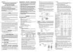
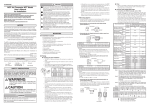
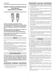
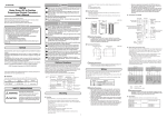
MCF
Air Flowmeter NPT Model
Measurement Module Replacement Manual
This manual describes how to replace the MCF measurement module.
Before attempting to replace the module, please take note of the points
below.
Please read the "Terms and Conditions" from the following URL before
ordering or use:
http://www.yamatake.com/products/bi/order.html
Unpacking
Check the following items when removing the MCF from its package:
Name
Part No.
Q'ty
Remarks
Measurement module
1
Unit conversion label
81424037-001
1
Packing
1
User's Manual
CP-UM-5573E
1
Replacement manual
CP-UM-5593E
1
This document
• Check the model number of the MCF measurement module
Measurement module
MCF model No.
81447192-203
81447192-223
MCF_ _ _ _ _ _ _ D01_ _ _ _
MCF_ _ _ _ _ _ _ D10_ _ _ _
Note
• However, the module for models with 4 -20 mA output can be used in RS-485
equipped models, and the module for models with RS-485 can be used in 4 to
20 mA models.
Precautions for Replacing the Measurement Module
CAUTION
When servicing or replacing the measurement module, release
the flowmeter's internal pressure before removing the
measurement module.
Handling Precautions
• The measurement module in models MCF0080, MCF0150 and
MCF0151 cannot be replaced.
After replacement of the measurement module, the accuracy guaranteed for MCF0250,
MCF0400, and MCF0500 flowmeters changes from ±3 %FS to ±5 %FS.
• If the measurement module of a model with RS-485 communications is replaced with a
module intended for a 4-20 mA output model, or if the module for a 4-20 mA output
model is replaced with a module for an RS-485 model, be sure to check that the wiring is
correct before turning on the power to the MCF main unit.
• When attaching/detaching the connector, note the following specifications for the cable
with VA connector:
(1)Tightening torque for the M12 nut on the connector cable
0.4 to 0.6 N • m
(2)Pullout strength for connector cable
40 N max.
(3)Bending stress for the connector cable
20 N max.
• When detaching the measurement module, wear safety goggles. Before replacing,
release the internal pressure of the flowmeter. Failure to do so may cause an accident
due to ejected gas.
• When installing the measurement module, take care that the rubber sheet and the built-in
filter remain in their proper locations. If these parts slip out of place during assembly,
external leakage or reduced accuracy may result.
• When attaching the measurement module, tighten the 4 bolts bit by bit, switching between
bolts in a diagonal pattern, until they reach the specified torque (2.6-3.3 N • m).
Part Names and Measurement Module Structure
EV
C02
C03
• If there is foreign matter or other blockage in the inlet or outlet of the
main flow path, the flow cannot be correctly measured.
(7) Make sure that the parts of new measurement module are assembled correctly. If the
rubber sheet is out of place, mount it on the flow path of the measurement module.
(8) Put the new packing on the main flow path, and then attach it to the main flow path
with the four bolts, matching the direction of the flow arrow on the label of the
measurement module with the direction of the flow arrow on the main flow path.
Tighten the bolts bit by bit to the specified torque, alternating bolts in a diagonal
pattern.
(9) After attaching the measurement module, connect the connector, turn on the power,
and then move to function setup mode. If the settings of the previous measurement
module are different from the initial values, change the settings.
(10)Next, move to parameter setup mode, and change the settings as required.
(11)Return to normal indication mode and move again to the function selection →
maintenance mode and change the settings. Temporary default numbers appear for
the flow path identifier and model number of the replacement measurement module.
Be sure to input the main flow path identifier number and the correct model number.
Rubber sheet
Case retaining
Connector screws
(Do not remove.)
Flow path
Built-in filter
• If the correct model number and flow path identifier are not input, the
flow will not be measured correctly.
• If the measurement module of a model with 4-20 mA output is replaced
with a replacement module, change the "Flow rate assignment for 20 mA
analog output" (Ao.20). Its default initial value is 3000 for all models, so it
should be changed to an appropriate value.
(12)Be sure that the indicated instantaneous flow rate is zero.
(13)Supply pressure to the flowmeter and to the inside of the pipe,
and make sure that the indicated instantaneous flow rate is
zero when there is no flow.
(14)After the measurement module is attached, make sure that
Date
there is no leakage.
(15)After replacement, write the replacement date in the "DATE"
space on the units conversion label, and affix the label to the air flowmeter.
CFM
CF
EV
AL
L/min
L
EV
AL
3
m/min
m3
EV
AL
3
m/h
m3
EV
AL
Bottom view of
measurement module
(without rubber sheet)
Inlet and outlet of measurement modu
Packing
kg/h
kg
EV
AL
Setting and Operation
■ State transitions
C07
Event standby
C08
C 10
Gas type
Operating pressure
C11
Reference
temperature
Integrated flow
option
C 14
Integrated flow
pulse width *2
C 15
Analog alarm
output *3
C30
Device address
*4
Transmission
speed *4
C3 1
[mode] key
2 s or more
Power ON
Instantaneous flow
rate display
[mode] key
Maintenance
mode
[mode] + [ ] key
2 s or more
[mode] key
[mode] key
2 s or more Function setup 2 s or more
mode
Integrated flow
last five digits
C32
Communication
conditions *4
Parameter setup
mode
C33
[mode] key
2 s or more
Communication
type *4
00: Unlocked
01: Key locked
00: L/min, L
01: m3/h, m3
02: m3/min, m3
03: kg/h, kg
04: CFH, CF
05: CFM, CF
00: Not used
01: Instantaneous flow rate upper limit
02: Instantaneous flow rate lower limit
03: Within range for instantaneous flow rate
04: Instantaneous flow rate upper limit
(reversed output) *2
05: Instantaneous flow rate lower limit
(reversed output) *2
06: Within range for instantaneous flow rate
(reversed output) *2
07: Set value reached by integrated flow count-up
08: Set value reached by integrated flow count-up
(reversed output) *2
09: Zero reached by integrated flow countdown
10: Zero reached by integrated flow countdown
(reversed output) *2
11: Integrated pulse output (minimum unit) *2
12: Integrated pulse output (minimum unit X 10) *2
13: Integrated pulse output (minimum unit X 100) *2
14: Alarm
15: Alarm (reversed output) *2
00: Instantaneous flow rate indication
01: Integrated flow last five digits
02: Integrated flow first four digits
03: No display
00: Disabled
01: Enabled
00: Air, nitrogen (fixed)
00: 0.3 MPa standard
01: 0.1 MPa standard
02: 0.5 MPa standard
03: 0.7 MPa standard
00 to 35: 0 to 35 ºC (every 1 ºC)
00: Integrate only normal flow
01: Integrate both normal flow and reverse flow
(as a minus)
00: 50 ms
01: 250 ms
02: 500 ms
00: Not used
01: Upper level (variable)
02: Lower level (fixed)
00 to 99
00: No communication
01: 19200 bps
02: 9600 bps
03: 4800 bps
00: 8-bit data, Even parity, Stop bit 1 (RTU)
01: 8-bit data, No parities, Stop bit 2 (RTU)
02: 7-bit data, Even parity, Stop bit 1 (ASCII)
03: 7-bit data, No parities, Stop bit 2 (ASCII)
00: MODBUS (RTU)
01: MODBUS (ASCII)
Initial Setting
value value
00
04
00
Flow direction arrow
3)
Blinking
[mode] key
(3) Push the [mode] key, and the left digit will blink.
(4) Use the[ ] or [ ] keys to increase or decrease the numeric value of the blinking
digit. Set the desired numerical value for each digit.
(5) When the desired value is set, press the [enter] key.
>> The setting is changed.
(6) Repeat steps (2) to (5) if you want to continue setup.
(7) To exit setup, while the parameter is displayed press and hold the [mode] key 2
seconds or more. The MCF returns to normal indication mode.
● Setup item list
Item
Name
00
00
00
00
00
00
00
00
00
02
00
00
Sample display during setup
[enter] key
Parameter setup
[enter] key
1
0 to 400 %FS *2
0 to 400 %FS *2
0 to 400 %FS
0 to 10 %FS
0 to 60 s
0 to 400 %FS
0 to 10 %FS
0 to 60 s
0.100 to 2.000
1 to 50 %FS
100 to 200 %FS
00000 to 99990
0000 to 9999
1.0 to 100.0
Initial Setting
value value
3000
0
0
1
0
0
1
0
1.000
2
200
0
0
1.0
● Setup method
(1) Press and hold the [mode] key for 2 seconds or more in the normal indication mode.
Then press and hold the [mode] key and [ ] key at the same time for 2 seconds.
(2) Move to the desired setup item with the [ ] or [ ] key, and then press [enter] key.
>> The current setting is shown with the rightmost digit blinking.
(3) If the [mode] key is pressed, the left digit blinks.
(4) Press [ ] or [ ] to increase or decrease the numeric value of the blinking digit. Set
the desired numerical value for each digit.
(5) When the desired value is set, press the [enter] key.
>> The setting is changed, and the parameter is displayed.
(6) Repeat the steps (2) to (5) if you want to continue setup.
(7) To exit setup, press and hold the [mode] key 2 for seconds or more while the setup
item is displayed. The MCF returns to normal indication mode.
● Setup item list
Item
FLt
CYCLE
b_Ovt
PSCF1
PSCF2
PSCF3
OP.0
OP.1
OP.2
SYS01
Setting range
Name
Calculation filter
Measuring period
Fixed output at alarmoccurrence (upper side) *3
Pressure correction adjustment
Pressure correction adjustment
Pressure correction adjustment
Flow path identifier 0 *1
Flow path identifier 1 *1
Flow path identifier 2 *1
Model number *2
PCOde Reserved
1 to 32
5 to 100 [X10ms]
0 to 120 %
0 to 2.000
0 to 2.000
0 to 2.000
0 to 32768
0 to 32768
0 to 32768
2=MCF0250
3=MCF0400
4=MCF0500
****
Initial Setting
value value
8
5
110
0.998
1.002
1.004
00000
00756
02175
2
0000
*1. For the flow path identifier of the new measurement module, enter the flow path
identifier that was read from the previous measurement module before
replacement. Alternatively, input the 15-digit number shown on the body of the
MCF, on the main flow path label.
XXXXX
Flow path
identifier 0
XXXXX
XXXXX
Flow path
identifier 1
Flow path
identifier 2
*2. Input the correct model number, matching the one on the main flow path.
*3. Not shown on models with RS-485 communications.
Example of parameter display
Parameter
selection
Setting range
Ao20 Flow rate assignment for 20 mA analog output *1
Ao04 Flow rate assignment for 4 mA analog output *1
E1.SP Event 1 instantaneous flow rate
E1.hyS Hysteresis for event 1
E1.dLY ON delay for event 1
E2.SP Event 2 instantaneous flow rate
E2.hYS Hysteresis for event 2
E2.dly ON delay for event 2
CF.
Output correction factor
Lfcvt Low flow cutoff
HI.Lt Upper limit for indication
EI.LO Last 5 digits of integrated flow (event setup)
EI.HI First 4 digits of integrated flow (event setup)
COSt Flow rate cost multiplier
● Setup method
(1) Push and hold the [mode] key 2 seconds or more in the normal indication mode. The
device enters function setup mode. Again press and hold the [mode] key 2 seconds
or more. The MCF enters parameter setup mode.
● Setup method
(1) Push and hold the [mode] key for 2 seconds or more in the normal indication mode.
>>The function number is displayed in the first 3 digits and the current setting is
displayed in the last 2 digits.
Blinking
■ Maintenance mode settings
*1. If you change the flow rate engineering unit, affix the appropriate unit label (included
with the MCF) on top of the current label.
*2. Does not function on RS-485 communications models.
*3. Can not be selected for RS-485 communications models.
*4. Can be selected for RS-485 communications models only.
[mode] key
2 s or more
(2) Move to the desired parameter by pushing [ ] or [ ] key, and then press [enter]
key.
>>The current setting is indicated with the rightmost digit blinking.
*1 Can be selected for 4-20mA output models only.
*2 When C02 is set to 04 or 05, the setting range is 0 to 200 % FS.
■ Parameter settings
After
Function
During
setup
selection
setup
[enter] key
[enter] key
Main flow path
Flow path identifier (5 digits
Normal indication
81424037-001-02
[ ] or [ ] key
Top view of main path
(Without measurement module)
XXXXX-XXXXX-XXXXX
C04
C 12
■ Function selection
Outlet
Event output
Setting range
Normal indication
AL
Bottom view of
measurement module
Unit of instantaneous
flow rate and
integrated flow *1
Handling Precautions
No display
[mode] key
enter
Inlet
Function
Name
number
C0 1
Key lock setting
[mode] key
MCF
CFH CF
• Do not rotate the connector cable at the neck while it is inserted in the
MCF. Doing so may rotate the connector, twisting and damaging the
wires inside.
(4) Release the air pressure from the flowmeter and from the piping, and then make sure
that the gauge pressure is zero.
(5) Loosen the four bolts holding the measurement module bit by
bit, and then remove both the measurement module and packing. Section of inlet and outlet
2mm dia.
If the rubber sheet and built-in filter are attached to the main
flow path, remove them also.
(6) Clean the entrance and inside of inlet and outlet holes on top of
the main path for the measurement module with a blower.
Integrated flow
first four digits
Measurement
module
mode
Handling Precautions
[mode] key
Flow direction arrow
Bolts
● Required items
Hex wrench (M5), air blower, protective goggles, helmet, and gloves
● Procedure
(1) Wear protective goggles, helmet, and gloves.
(2) In order to transfer the settings from the present measurement module to the new one,
read the function settings, parameter settings, and maintenance mode settings, and
record them in the tables on the next page. For help in navigating between the modes,
refer to the state transitions chart.
(3) Turn off the power, and disconnect the connector.
Handling Precautions
model number
With 4 to 20 mA output
With RS-485 communications
Flow rate display
(2) Change the function setup to the desired item by pushing [ ] or [ ] key, and then
press [enter] key.
>>The function setup number goes out, and the only the setting (in the last 2 digits) is
shown.
(3) Change the setting with the [ ] or [ ] key, and then press [enter] key.
>>The changed setting is now entered, and both the function number and the setting
are shown.
If the [mode] key is pressed instead of the [enter] key, the MCF exits setup mode
without changing the setting.
(4) Repeat steps (2) to (3) if you want to continue setup.
To exit setup mode, press and hold the [mode] key for 2 seconds or more to move to
parameter setup, and then again press and hold the [mode] key for 2 seconds or more
to return to normal indication mode.
● Function settings
Replacement of the Measurement Module
CP-UM-5593E
[mode] key
2 s or more
After
setup
During
setup
[enter] key
Normal indication
(Instantaneous flow rate/
integrated flow/no display)
Specifications are subject to change without notice. (08)
Advanced Automation Company
1-12-2 Kawana, Fujisawa
Kanagawa 251-8522 Japan
URL: http://www.azbil.com
1st Edition: Issued in June 2009 (M)