1
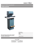
NUMBERALL
STAMP & TOOL CO., INC.
USER MANUAL & PARTS LIST
MODEL
301
S/N:
___________________________
P.O. BOX 187, 1 HIGH ST.
SANGERVILLE, ME 04479
www.numberall.com
[email protected]
TEL: 207-876-3541
FAX: 207-876-3566
MODEL 301 HAND-OPERATED
ROLL MARKING PRESS
Uncrating Procedure
1. The Model 301 is shipped bolted to a wooden skid. It is covered with a
cardboard box that is stapled and banded to the wooden skid.
2. Cut the plastic shipping bands. Cut the cardboard box all the way around,
within a couple of inches of the top of the wooden skid.
3. Lift off the cardboard cover, remove the protective plastic bag and unbolt the
press.
4. The Model 301 weighs 80 pounds and should be lifted with caution.
5. Bolt the press securely to a solid bench to avoid accidental upset.
6. The Model 301 is capable of forces exceeding 2 tons. KEEP BOTH HANDS
FREE OF THE TABLE AREA WHEN OPERATING THE PRESS HANDLE.
7. Any shipping damage to the press must be reported immediately to the
common carrier and to Numberall.
Product Description
The Model 301 is a versatile and compact press, designed for stamping small,
round parts. By using a roller die flat parts can be stamped. The Model 301 is an
ideal choice where bench space is restricted. It is intended for continuous, heavyduty use.
Bench area is 10” x 14-1/2” x 15-1/2” high. The mounting base is 10-1/2” x 14”
(outside dimensions). Platform area is 7-1/2” x 11”. Maximum clearance between
the ram and table is 5-3/4”, and table vertical travel is 1-3/4”. Lateral travel is 51/2”.
An automatic tripping attachment is another option available, which when using
the Model 50 Numbering Machine, allows the Model 50 to advance to the next
consecutive number.
Revision # 2.0
Maximum Character Chart
For Models 301, 301A Presses
The Model 301 can easily exert a 2-ton force. The following chart depicts the
maximum number of characters the Model 301 is capable of stamping during
each impression, based on character size and type of material. The chart is
conservative, so the recommendations can be exceeded in many cases.
Variations in the hardness of a material will affect stamping results.
Character
Size
Mild Steel
Aluminum
1/4
1
2
3/16
2
2
5/32
2
3
1/8
3
3
3/32
3
3
1/16
3
3
Note: The above chart is based upon the maximum number of characters for a
legible impression (.002”-.003” depth).
Function of Controls
1. OPERATING HANDLE (301-384) - The operating handle is used to move the
sliding head left and right across the work. If the vertical adjustment of the
dovetail slide (301-402) is correct, little effort is required to push or pull the
handle.
2. DEPTH OF IMPRESSION KNOB (301-388) - The depth of impression
adjustment knob is located on the top of the sliding head. Turning the knob
counter-clockwise raises the marking device and turning the knob clockwise
lowers the marking device.
3. TORQUE BAR GIBS (301-394) - These gibs, located above and below the
torque bar (301-398), allow vertical adjustment of the sliding head. If play
develops in the sliding head, or the dovetail slide is not perpendicular to the
base plate, it will be necessary to adjust these gibs. Loosen all of the jam
nuts. Evenly screw the top two set screws in or out as required, while evenly
Revision # 2.0
turning the bottom two set screws in the opposite direction. Do not overtighten. The gibs are adjusted correctly when the dovetail slide is
perpendicular to the base, and the sliding head has no play. Retighten the
jam nuts, while holding the set screws stationary.
4. DOVETAIL RAM GIB (301-394) - This gib, located between the dovetail ram
(301-402) and the sliding head (301-392), eliminates play in the ram head. If
the ram head develops left and right play, it will be necessary to tighten the
gib. While holding the two allen head set screws (301-396) stationary, loosen
the locking nut on each. Evenly tighten the two set screws until left and right
play is eliminated. Do not over-tighten. While holding the two allen head set
screws stationary, retighten the locking nuts. This adjustment may be
required after initial break-in.
5. MARKING DEVICE MOUNTING SCREW (301-404) - This button-head
machine screw holds the marking device against the dovetail slide.
6. MARKING DEVICE ALIGNING SCREWS - These two allen set screws are
located near the bottom of the dovetail slide on the left and right hand sides.
They serve to adjust and tighten the marking device. By turning one set screw
in, while turning the other out, the angle of the marking device, relative to the
base, can be changed. Both should be tight for marking.
7. ADJUSTABLE HOLDING FIXTURE - This fixture is mounted with four cap
screws to the base plate. The axes of the rolls must be parallel to the endplate casting, in order to produce satisfactory roll marking. After squaring the
edge of the fixture with the end plate, only tighten the two right-hand cap
screws. These should remain tight unless the fixture needs to be re-aligned.
The two left-hand cap screws are tightened after the roll spacing has been
adjusted to the diameter of the part to be marked. The rolls should remain as
close as practical, since it minimizes press force. Tighten the left-hand cap
screws after adjustment.
Adjustments for Stamping
1. Keep both hands free of the base area when moving the operating handle.
2. Set up the adjustable holding fixture.
3. Attach the marking device to the dovetail slide, tightening the mounting screw
and two set screws.
4. Turn the depth of impression adjustment knob counter-clockwise until the
marking device is higher than the part.
5. Move the operating handle slowly, making sure the marking device clears the
part.
Revision # 2.0
6. Stop the handle when the marking device is above the part. Slowly rotate the
depth of impression adjustment knob until it touches the part. Move the
operating handle to the end. Rotate the knob 1/16 of a turn and try a sample
stamping. It may be necessary to repeat this until a satisfactory depth is
obtained.
7. The marking device should not chatter violently as it passes over the part. If it
does, reduce the depth of impression.
8. If the work creeps fore and aft in the adjustable holding fixture, then the fixture
needs to be aligned.
9. If the impression is uneven back to front, the dovetail slide is not
perpendicular to the base and needs to be aligned.
10. If the impression is uneven, beginning to end, around the circumference, the
marking device set screws need adjustment.
Lubrication
1. Oil holes are provided in the following places:
a. On the sliding head, just below the depth of impression adjustment knob.
b. On the sliding head, just above the sliding head shaft, left and right.
c. On the cannon, just above the cannon pivot screw.
d. On the frame casting, just inside of the operating handle.
Use a few drops of light oil in these places if the surface appears dry. Oil daily if
the press is in continuous service.
2. Place a few drops of oil on the dovetail slides and the surfaces of the torque
bar, if these surfaces appear dry. Oil weekly if the press is in continuous use.
Revision # 2.0
Numberall Stamp & Tool Co., Inc.
For extra copies of this manual please call or
visit our website.
P.O. BOX 187, 1 HIGH ST.
SANGERVILLE, ME 04479
www.numberall.com
[email protected]
TEL: 207-876-3541
FAX: 207-876-3566