1
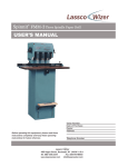
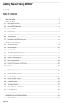
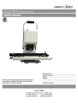
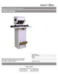
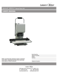
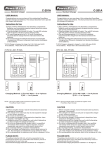
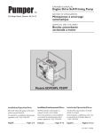
CR-50P
Cornerounder
R
USER’S MANUAL
ProSource Packaging, Inc.
14911 Stuebner Airline Suite A
Houston, TX 77069
800-203-0233
www.Machine-Solution.com
Before operating this equipment, please read these
instructions completely and keep these operating
instructions for future reference.
Serial Number:
Date of Purchase:
Dealer:
Address:
Telephone Number:
485 Hague Street, Rochester, NY 14606 U.S.A.
Tel: 585-436-1934
Fax: 585-464-8665
www.lasscowizer.com
[email protected]
Table Of Contents
1 - Introduction
1.1
1.2
Your New CR-50P................................ Page 01
Shipping Damage Inspection............... Page 01
2 - Safety
2.1
2.2
2.3
Safety Instructions................................ Page 02
Warning Labels..................................... Page 03
Grounding Instructions......................... Page 04
3 - Setting Up Your Machine
3.1
3.2
3.3
3.4
3.5
3.6
Installing the Leveling Feet.................. Page 05
Electrical Start Up................................ Page 05
Cutting Unit Installation (Standard &
Special Sizes)....................................... Page 06
Cutting Unit Installation (Large Sizes).. Page 07
Adjusting the Side Guides.................... Page 07
Adjusting the Pressure Foot................. Page 08
4 - Operation
4.1
4.2
4.3
Corner Rounding Operation................. Page 08
Cutting Unit Capacities......................... Page 08
Chip Removal....................................... Page 08
5 - Maintenance
5.1
5.2
Safety.................................................... Page 09
Annual Lubrication................................ Page 09
1 - Introduction
1.1 - Your New CR-50P
Thank you for your purchase of the CR-50P
Cornerounder .
R
We ask that you take a moment to fill in the serial
number and other information on the front cover of the
manual. Please keep this manual as a reference for
future use.
For parts and service, please contact the Lassco-Wizer
Dealer from whom you purchased the machine. If you
require assistance in locating a Lassco-Wizer Dealer
please contact our customer service department at 585436-1934. Please have the model of your machine and
the serial number when you call.
If you wish to write to us, send correspondence to:
Lassco-Wizer
Attn: Customer Service
485 Hague Street
Rochester, NY 14606
1.2 - Shipping Damage Inspection
Remove the machine from the carton and inspect for
any shipping damage. If any damage is present, report
the damage to the carrier immediately; failure to do so
may void any warranties.
6 - Parts Diagram
6.1
Determining the Cause and Correction
to Certain Problems.............................. Page 09
7 - Parts Diagram
7.1
7.2
Parts Diagram....................................... Page 11
Parts List.............................................. Page 12
Page 01
2 - Safety
2.1 - Safety Instructions
All operators must read and understand the Users
Manual including all safety instructions before using this
equipment. Failure to fully understand the safety
instructions can result in personal injury. If after reading the
manual you are still uncertain about use, please
contact the dealer from whom you purchased the
machine for assistance. If you need contact information for
a Service Technician nearest you please call
585-436-1934.
CHECK DAMAGED PARTS. Before further use of the machine, a guard or other part that is damaged should be carefully checked to determine that it will operate properly and
perform its intended function--check for alignment of moving
parts, binding of moving parts, breakage of parts, mounting, and any other conditions that may affect its operation.
A guard or other part that is damaged should be properly
repair or replaced.
SAFETY OF THIS EQUIPMENT IS THE RESPONSIBILITY
OF THE USER(S).
NEVER LEAVE MACHINE RUNNING UNATTENDED.
TURN POWER OFF. Don’t leave machine until it comes to
a complete stop.
Please read and follow all warning labels on your machine.
DO NOT REMOVE PRESSURE FOOT ASSEMBLY
Keep hands clear while operating machine.
KEEP WORK AREA CLEAN. Cluttered areas and benches
invite accidents.
ALWAYS USE SAFETY GLASSES. Everyday eyeglasses
only have impact resistant lenses, they are NOT safety
glasses.
KEEP GUARDS IN PLACE and in working order.
Always disconnect the power before servicing this machine.
Service should only be performed by a QUALIFIED TECHNICIAN.
DON’T USE IN DANGEROUS ENVIRONMENT. Don’t use
this machine in damp or wet locations, or expose it to rain.
Keep work area well lighted.
THIS MACHINE IS DESIGNED FOR ONE PERSON OPERATION. Never operate the machine with more than one
person.
KEEP CHILDREN AWAY. All visitors should be kept a safe
distance from the work area.
USE RIGHT MACHINE. Don’t force tool or attachment to
do a job for which it was not designed.
MAINTAIN MACHINE WITH CARE. Keep tools sharp and
clean for best and safest performance. Follow instructions
for changing accessories.
DON’T FORCE TOOL. It will do the job better and safer at
the rate for which it was designed.
USE PROPER EXTENSION CORD. Make sure your extension cord is in good condition. When using an extension
cord, be sure to use one heavy enough to carry the current
your product will draw. An undersized cord will cause a drop
in line voltage resulting in the loss of power and overheating. Cord Size should be 18 AWG for 0-25 feet long, 16
AWG for 50-200 feet long, and 14 AWG for 150-300 feet
long. If in doubt, use the next heavier gauge. The smaller
the gauge number, the heavier the cord.
WEAR PROPER APPAREL. Do not wear loose clothing,
gloves, neckties, rings, bracelets, or other jewelry or clothing which may get caught in moving parts. Non-slip footwear is recommended. Wear protective hair covering to
contain long hair.
SECURE WORK. Use Pressure Foot Assembly to hold
work. It’s safer than using your hand.
DO NOT USE ACCESSORIES WITH THIS PRODUCT.
Use of accessories or attachments may result in a risk of
injury to persons.
DISCONNECT MACHINE when changing accessories,
such as cutting units.
REDUCE THE RISK OF UNINTENTIONAL STARTING.
Make sure the power switch is in the off position before
plugging in.
NEVER STAND ON MACHINE. Serious injury could occur
if the machine is tipped.
DO NOT OVERREACH. Keep proper footing and balance
at all times.
Page 02
2 - Safety
2.2 - Warning Labels
English
WARNING: DO NOT EXPOSE TO RAIN
OR USE IN DAMP LOCATIONS.
French
AVERTISSEMENT: NE PAS EXPOSER
À LA PLUIE ET NE PAS UTILISER DANS
LES EMPLACEMENTS HUMIDES
Page 03
2 - Safety
2.3 - Grounding Instructions
Diagram 2-10
METAL SCREW
GROUNDING
PIN
COVER OF GROUNDED
OUTLET BOX
In the event of a malfunction or breakdown, grounding provides a path of least resistance for electric current to reduce the risk of electric shock. This tool is equipped with an electric cord having an equipment-grounding conductor and a grounding plug. The plug must be plugged into a matching outlet that is properly installed and grounded
in accordance with all local codes and ordinances.
DO NOT MODIFY THE PLUG PROVIDED. If it will not fit the outlet, have the proper outlet installed by a QUALIFIED ELECTRICIAN.
Improper connection of the equipment-grounding conductor can result in a risk of electric shock. The conductor
with insulation having an outer surface that is green with or without yellow stripes is the equipment-grounding conductor. If repair or replacement of the electric cord or plug is necessary, do not connect the equipment-grounding
conductor to a live terminal. Check with a QUALIFIED ELECTRICIAN or service personnel if the grounding instructions are not completely understood, or if in doubt as to whether the tool is properly grounded. Use only 3-wire
extension cords that have 3-prong grounding plugs and 3-pole receptacles that accept the machine’s plug.
This machine is intended for use on a circuit that has an outlet that looks like the one illustrated in diagram 2-10.
The machine has a grounding plug that looks like the plug illustrated in diagram 2-10. Make sure the machine is
connected to an outlet having the same configuration as the plug. No adapter is available or should be used with
this machine. If the machine must be reconnected for use on a different type of electric circuit, the reconnection
should be made by qualified service personnel; and after reconnection, the tool should comply with all local codes
and ordinances.
Page 04
3 - Setting Up Your Machine
3.1 - Installing the Leveling Feet
3.1.1
Set the machine down in its desired location and determine if the
machine is level, making sure that it does NOT rock in any direction. If it does, determine which Leveling Feet need to be adjusted
and whether they need to be adjusted up or down.
3.1.2
If adjustment is needed, start by loosening the four (4) nuts which
are accessed through the rear of the machine.
3.1.3
Next adjust the four (4) Leveling Feet by screwing them clockwise
to raise the or counter-clockwise to lower. After each adjustment
set the machine down completely to verify that the machine no
longer rocks. Continue adjustment as needed until the machine
sits securely in place. Tighten the four (4) nuts down to secure the
position of the Leveling Feet.
Nut
Leveling Feet
Base of the Machine
3.2 - Electrical Start Up
3.2.1
Your CR-50P comes with an electrical cord containing the plug to
fit into a standard grounded 115V outlet.
3.2.2
Your CR-50P also has a power switch with keyed lock-out. Make
sure that the key is removed before continuing on to step 3.2.3.
Also make sure that the key is removed while setting up the machine, while performing maintenance, and while the machine is
not being used; this will help prevent unwanted activiation of moving parts that can crush or cut.
3.2.3
Making sure that nothing is interfering with the cutting unit, plug
the cord set into a grounded 115V outlet. To turn the machine on,
press the Rocker Switch on the front of the machine up. To turn
the machine off press the Rocker Switch on the front of the
machine down.
3.2.4
To activate the machine, insert the key into the power switch and
rotate clockwise. To Turn the machine off, turn rotate the key
counter-clockwise and remove to ensure Lock-Out.
Power Cord
Key
Power Switch
Page 05
3 - Setting Up Your Machine
3.3 - Cutting Unit Installation (Standard & Special Sizes)
3.3.1
Loosen the Top Yoke Wing Nut (50-34) on the right hand side of the Top Yoke (50-15) and swing the Top Yoke
toward you to obtain access to the Cutting Unit Cavity in the Table Ring Casting (50-14).
3.3.2
Making sure the Adapter Hold Down Tab (50-11) is not in the way, insert the Adapter Plate (50-26) into the Table
Ring Casting. Make sure that the Adapter Plate Rotation Tab (50-12) slips under the Table Ring Casting into its
designated groove to prevent unwanted rotation of the Adapter Plate. Turn the Adapter Hold Down Tab so that it
locks the Adapter Plate into place.
3.3.3
Insert the Cutting Unit into the Adapter Plate.
3.3.4
Swing the Top Yoke back into its original position making sure it is fully engaged in the Yoke Slide Rod (50-04).
Tighten down the Top Yoke Wing Nut to secure in place.
3.3.5
Depress the Foot Pedal to engage the cutting cycle making sure to check that the Cutting Unit is working
properly.
Standard / Special Size
Cutting Unit (Misc Part #)
Adapter Plate (50-26)
Adapter Plate Roation Tab (50-12)
Adapter Hold Down Tab (50-11)
Top Yoke Wing Nut (50-34)
Pressure Foot Assembly
(50-201A)
Yoke Slide Rod (50-04)
Cutting Unit Cavity
Top Yoke (50-15)
Side Guide (50-03R)
Wood Table (50-29)
Side Guide (50-03L)
Table Ring Casting (50-14)
Page 06
3 - Setting Up Your Machine
3.4 - Cutting Unit Installation (Large Sizes)
3.4.1
Loosen the Top Yoke Wing Nut (50-34) on the right hand side of the Top Yoke (50-15) and swing the Top Yoke as
shown to obtain access to the Cutting Unit Cavity in the Table Ring Casting (50-14).
3.4.2
Make sure the Adapter Plate has been removed.
3.4.3
Insert the Large Size Cutting Unit into the Table Ring Casting by tilting and seating it and pushing back and down
until it is secure in place. Make sure the Rotation Tab on the Cutting Unit slips under the Table Ring Casting into
its designated groove to prevent unwanted rotation of the Cutting Unit. Turn the Adapter Hold Down Tab (50-11)
so that it locks the Cutting Unit into place.
3.4.4
Swing the Top Yoke back into its original position making sure it is fully engaged in the Yoke Slide Rod (50-04).
Tighten down the Top Yoke Wing Nut to secure in place.
3.4.5
Depress the Foot Pedal to engage the cutting cycle making sure to check that the Cutting Unit is working
properly.
Large Cutting Unit
(Misc Part #)
Rotation Tab
Adapter Hold Down Tab (50-11)
Top Yoke Wing Nut (50-34)
Pressure Foot Assembly
(50-201A)
Yoke Slide Rod (50-04)
Cutting Unit Cavity
Top Yoke (50-15)
Side Guide (50-03R)
Wood Table (50-29)
Side Guide (50-03L)
Table Ring Casting (50-14)
3.5 - Adjusting the Side Guides
3.5.1
Adjust the Side Guides so that they are square with the cutting unit you are using. We recommend using a right
angle tool (not included).
3.5.2
Slide the tool into the corner of the Cutting Unit making sure it is square with both edges of the Knife.
3.5.3
Loosen the Screws on the Side Guides and adjust as needed. Re-tighten the screws to secure the Side Guides.
Page 07
3 - Setting Up Your Machine
3.6 - Adjusting the Pressure Foot
PRESSURE FOOT ASSEMBLY IS NOT REMOVEABLE
3.6.1
3.6.2
Wing Nut
Hex Nut
Thumb
Screw
To adjust horizontally (depending on the size of the Cutting Unit)
loosen the center Thumb Screw on the Top Yoke, adjust in or out
until the Pressure Foot clears the black guard on the Cutting Unit.
Secure by tightening the center Wing Nut down.
Adjust the Pressure Foot clamping pressure to accommodate different product heights. Loosen the Wing Nut on the top of the
Pressure Foot. Tighten the Hex Nut underneath to increase the
pressure Loosen the Hex Nut to decrease pressure. When the
pressure is set as desired tighten down the Wing Nut to lock the
tension in place.
E-clip
Pressure Foot
Top Yoke
4 - Operation
4.1 - Corner Rounding Operation
4.1.1
Place the product you are cutting onto the Wooden Top Plate and push it into the corner aligning it with the Two Side
guides.
4.1.2
Press down firmly to prevent the product from sliding out of the corner.
4.1.3
Depress the Foot Pedal once to engage the cutting cycle. The Pressure Foot will come down helping to secure the
product in place. The Cutting Unit will cycle through once.
4.1.4
If you hold down the Foot Pedal, the Cutting Unit will cycle through at the rate of 30 strokes per minute. Rotate the
product as the Pressure Foot rises releasing its pressure on the product.
4.1.5
Repeat as needed
4.1.6
It may be necessary to adjust the Side Guides to compensate for variation in the cutting unit geometry, especially
when changing from a Standard / Special Size Cutting Unit to a Large Size Cutting Unit.
4.2 - Cutting Unit Capacities
4.2.1
Standard / Special Size Cutting Units:
These size Cutting Units were designed to handle up to a 1/2” stack of paper. They will also cut many other materials
such as plastics, cardboard, celluloid, leather, wood, and even light soft metals. With heavier materials, however,
best results may be obtained if only one or a few pieces are cut at a time.
4.1.2
Large Size Cutting Units:
These size Cutting Units were designed to handle up to a 1/8” stack of paper. They will also cut many other materials such as plastics, cardboard, celluloid, leather, and wood. With heavier materials, however, best results may be
obtained if only one or a few pieces are cut at a time.
4.3 - Chip Removal
4.3.1
Place a waste bin or a disposable basket underneath the Chip Chute on the rear of the machine. This will catch the
chips as they are cut and slide down the Chip Chute. Empty as needed.
Page 08
5 - Maintenance
5.1 - Safety
ALWAYS DISCONNECT THE POWER BEFORE PERFORMING MAINTENANCE
ON THIS MACHINE. MAINTENANCE SHOULD ONLY BE PERFORMED BY A
QUALIFIED TECHNICIAN.
KEEP HANDS CLEAR WHILE PERFORMING MAINTENANCE ON THIS MACHINE.
MOVING PARTS CAN CRUSH AND CUT.
5.2 - Annual Lubrication
5.2.1
Lightly oil the two Yoke Slide Rods where they enter the adapter ring approximately every two weeks or as needed
depending on use.
5.2.2
Remove the back panel and lightly oil the connection where the Draw Bar and Cam Bar pivot every 30 days or as
needed depending on use.
6 - Troubleshooting
6.1 - Determining the Cause and Correction to Certain Problems
Problem
Cause
Correction
Machine makes a squeak
during operation
This is inherent in the motor itself
and is a normal during operation
No correction is needed
Machine won’t start
Power supply insufficient
Inspect and test power supply
Fuse has blown
Replace fuse
Grinding noise from motor
when stopping or reaching
full cycle
Faulty Brake-Hub Assembly
Contact a Qualified Service
Technician
Machine will not cycle or cut
material
Material is too thick or too hard
Decrease the size of the stack
you are attempting to cut
Page 09
6 - Troubleshooting
6.1 - Determining the Cause and Correction to Certain Problems
Problem
Cause
Machine cycles continuously
Correction
Foot Pedal stuck in depressed
mode
Replace foot pedal
Micro-Switch is faulty or out of
adjustment
See Micro-Switch adjustment
below
To properly adjust the Micro-Switch:
6.1.1
Rotate the motor until the Cam Block is at the top dead center as shown in the diagram below.
6.1.2
Reposition the Micro-Switch so that there is a 1/16” gap between the Micro-Switch Roller and the angle on the
Switch Actuator Shaft. There should also be a 1/16” gap between the Micro-Switch Roller and the narrow diameter
of the Switch Actuator Shaft as shown in the diagram below.
Slide Yoke Bars
Switch Actuator
Shaft
Bottom Yoke
Casting
Switch Actuator
Shaft
Micro-Switch
Adjustment Clevis
Micro-Switch
Support
Pull Bar
Micro-Switch
Roller
1/16” Gap
Cam Block
1/16” Gap
Micro-Switch
Roller
Motor
Page 10
6 - Parts Diagram
6.1 - Parts Diagram
Page 11
6 - Parts Diagram
6.2 - Parts List
50-26: Adapter Plate
50-12: Adapter Plate Rotation Tab
50-15: Top Yoke
50-201A: Pressure Foot Assembly
50-03L: Left Paper Guide (50-03R: Right Paper Guide Not Shown)
50P-80: Wood Table
50-04: Yoke Slide Rods
50P-41: Bottom Yoke
50P-22: Microswitch Actuator
50P-2000A: Microswitch Assembly
FM-42 & 50-31: Clevis & Clevis Pin
50P-3000A: Upper Chute Assembly
50P-60: Pull Bar
50P-61: Cam Block
50P-2004A: Gear Motor Assembly
50P-24: Motor Face Support
50P-25: Plastic Junction Box
50P-26: Junction Box Cover with Screws
EBM-68: Toggle Switch
Cord Set
50P-27: Foot Switch
50P-90: Back Cover
L-1001: 3 AMP Fuse
Page 12