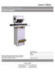
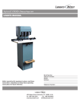
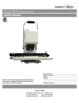
1
Before operating this equipment, please read these
instructions completely and keep these operating
instructions for future reference.
Serial Number:
Date of Purchase:
Dealer:
Address:
Telephone Number:
485 Hague Street, Rochester, NY 14606 U.S.A.
Tel: 585-436-1934
Fax: 585-464-8665
www.lasscowizer.com
[email protected]
Table Of Contents
Introduction
Introduction....................................................................... Page 02
Shipping Damage Inspection............................................ Page 02
Safety Information
Safety Instructions............................................................ Page 03
Warning Labels................................................................. Page 03
Setting Up Your Machine
Loose Item Inventory........................................................ Page 04
Leveling Feet.................................................................... Page 05
Paper Side Stops.............................................................. Page 05
Master Chip Chute............................................................ Page 05
Chip Bag........................................................................... Page 06
Electrical Start Up............................................................. Page 06
Operating Instructions
Drill Bit Removal and Installation...................................... Page 07
Leveling the Drill Bits........................................................ Page 08
Adjusting the Table Height................................................ Page 09
Back Gauge Adjustment................................................... Page 09
Adjusting the Distance Between the Heads...................... Page 10
Adjusting the Stop Collars................................................. Page 10
Multi-hole Set Up...............................................................Page 11
Traversing the Table..........................................................Page 11
Drilling Procedures............................................................ Page 12
Tips On Drilling..................................................................Page 12
Maintenance
Every 12 Months.............................................................. Page 13 - 15
Trouble Shooting Guide
Problem,Cause, and Correction........................................ Page 16 - 18
Parts Diagrams
Side View.......................................................................... Page 19
Head Assembly................................................................. Page 20
Spindle and Chuck Assembly........................................... Page 21
Rear View.......................................................................... Page 22
Parts List........................................................................... Page 23
Page 01
Introduction
Introduction
Thank you for your purchase of the Spinnit FMM-3 Paper Drill.
We ask that you take a moment to fill in the serial number and other information
on the front cover of this manual. Please keep this manual as a reference for
future use.
For parts and service please contact the Lassco-Wizer Dealer from whom you
purchased the machine. If you require assistance in locating a Lassco-Wizer
Dealer, please contact our customer service department at
585-436-1934. Please have the model of your machine and the serial number
when you call.
If you wish to write to us please contact us at:
Lassco-Wizer
485 Hague Street
Rochester, NY 14606
Shipping Damage Inspection
Remove the machine from the carton and inspect for any shipping damage. If any
damage is present, report the damage to the carrier immediately. Failure to do so
may void any warranties.
Page 02
Safety Information
Safety Instructions
All operators must read and understand the Users Manual and all other safety instructions before using this equipment. Failure to fully understand the safety instructions may
result in personal injury. If, after reading the manual, you are still uncertain about use,
please contact the dealer from whom you purchased the machine for assistance. If you
need contact information for a Service Technician nearest you please call 585-436-1934.
Safe operation of this equipment is the responsibility of the users.
This machine is designed for one person operation. Never operate the machine with
more than one person.
Keep hands, hair, and loose clothing away from the drills when operating.
Please read and follow all warning labels on your machine. (See below for a list of all
warning labels)
Always turn the machine to off mode and unplug the machine before installing or removing drill bits and before servicing the machine. Keep hands away from drills when
operating. PLEASE NOTE THAT THE DRILL BITS MAY BE HOT AFTER USE. PROCEED WITH CAUTION WHEN CHANGING THE DRILL BITS.
ONLY A SERVICING TECHNICIAN IS TO SERVICE THIS MACHINE.
Warning Labels
The following labels appear on your FMM-3 paper drill. Make sure all operators understand
and follow the safety instructions.
Please read and make sure that all operators understand the user’s
manual and all other safety instructions before using this equipment.
Keep hair, jewelry, loose clothing and any other items that could become
entangled pulled back away from the machine when drilling.
Page 03
Setting Up Your Machine
Loose Item Inventory
Remove and inspect the following items:
FMM6-651A: Master Chip Chute (1)
FM4-4001: 25” Drill Strip (1)
This item comes installed
FMM6-652A: Chip Bag Assembly (1)
MS-1: Drill Sharpener (1)
Hollow Drill Bit (3)
These items come installed
FM4-4006: Paper Side Stops (2)
Spin-Eze :
Drill Bit Lubricant (1)
EBM-41:
Sharpending
Stone (1)
HEX-532-T: Hex Wrench 5/32” (1)
EBM-32:
Chuck Release Key (1)
FMM9-956A: Spindle Rotation Tool (1)
CC-2: Chip Clearer (1)
FM4-4007: Side Stop Screws (4)
HEX-332:
Hex Wrench 3/32” (1)
Short Set Screws (2)
Items are not to scale
Page 04
Setting Up Your Machine
Leveling Feet
Step #1
If needed, adjust the feet on the underside of the base to
level the machine. Start by loosening the Lock Nuts
from inside the stand. Level by rotating the feet up or
down to the desired height as shown. When they are
adjusted as desired, tighten down the Lock Nuts again.
Nut
Leveling Feet
Base of the Machine
Paper Side Stops
Step #2
Attach the Paper Side Stops (FM4-4006) using two Side
Stop Screws (FM4-4007) each. Position the Paper Side
Stop as desired and tighten down with light pressure.
Side Stop Screws
Paper Side Stop
Table
Master Chip Chute
Step #3
Attach the Master Chip Chute (FMM6-651A) by inserting
the two hooks located on the wide end of the Master
Chip Chute into the rectangular opening in the upright as
shown. The hooks are on the bottom of the Master Chip
Chute and hook over the bottom of the opening.
Chip Chutes
Master Chip Chute
Page 05
Setting Up Your Machine
Chip Bag
Step #4
Attach the Chip Bag (FMM6-650A) to the machine by
stretching the mouth of the bag over the Master Chip
Chute and hooking the aluminum bar onto the bracket
located on the top flat portion of the master chip chute as
shown. Please note that you must empty this bag as
needed to avoid clogging.
Master Chip Chute
Chip Bag
Electrical Start Up
Step #5
Making sure that nothing is interfering with the drill bits,
plug the cord set into a grounded 115V outlet. To turn
the machine on, press the Rocker Switch on the front of
the shroud.
Rocker Switch
Power Cord
Page 06
Operating Instructions
Drill Bit Removal And Installation
Note:
Step #1
Please note that drill bits may be hot after drilling. Please wait to
change drill bits until they have cooled down.
Remove the hole guard which is attached to the chuck. This
is done by grasping the tab and sliding the guard off.
Chip Chute
Chuck Release Key
Tab
Chuck
Hole Guard
Step #2
Using the Chuck Release Key (EBM-32), insert the tapered
end facing down into the chuck hole. With a clockwise motion
turn the Chuck Release Key 45 degrees. The drill bit will slide
out of the spindle. It is recommended that you hold onto the
drill bit so that it does not drop out of the spindle damaging the
tip. Place the hole guard back onto the chuck to protect debris
from clogging the spindle.
Step #3
To install a drill bit, grasp the drill bit and being
careful to keep it straight, press it up into the Chuck.
Drill Bit
Chip Chute
Chuck
Hole Guard
Drill Bit
Step #4
Seat the drill bit by using a stack of scrap paper. Set the
scrap on the table as shown. Step on the foot pedal
slowly raising the table toward the drill bit. Put light
pressure on the hollow drill bit seating it firmly in place.
Remove the scrap paper and turn the machine on to
check the concentricity of the bit. If the bit is not concentric, remove it and repeat steps 3 and 4 until it is concentric.
Page 07
Operating Instructions
Leveling The Drill Bits
Step #5
To level the Drill Bits:
Spindle Rotation Tool
1. Insert the Spindle Rotation Tool (FMM9-956A) into
the end of the motor shaft through the opening in the
top of the machine shroud.
2. Swing the access cover located on the front of the
heads to one side allowing access to the spindle and
chuck.
3. Turn the Spindle Rotation Tool by hand until the insert
retainer screw can be seen in the opening.
Access Cover
4. Stepping slowly on the foot pedal, raise the table so
that it meets the bottom of the pressure foot assembly.
Pressure Foot
5. Using the 5/32” Hex Wrench (HEX-532-T), loosen the
insert retainer screw and lower the chuck by pulling
down on it until the drill bits meet the table surface.
6. When the drill bit is just touching the drill strip,
re-tighten the insert retainer screw.
7. Repeat steps 1 - 6 on the remaing Drill Bits so that
they are all level with each other.
8. Remove the Spindle Rotation Tool from the motor
shaft.
Table
9. Replace the access covers so that they cover the
openings.
Note:
We recommend using a piece of card stock on the Table
when leveling the drill bits to avoid drilling into the drill strip.
This will lengthen the life of your drill bits and keep them
sharper.
Chuck
Card Stock
Table
Page 08
5/32 Hex Wrench
Insert Retainer
Screw
Operating Instructions
Adjusting the Table Height
Step #6
After you level the drill bits you may need to adjust your table
height. Test drill through a stack of scrap approximately the
same height as that you will be drilling. If the drill bits drill into
the Drill Strip or if the drill bits fail to penetrate through the
bottom sheet of scrap you will need to adjust the table height.
If you are using the card stock under your scrap
(recommended) then you should just be lightly scoring the
card stock when the table is in its full upright position. If your
bits are drilling correctly move onto Step #7.
Table
Lock Knob
Vertical Stop
Adjustment
If your drill bits fail to penetrate through the scrap:
Loosen the Lock Knob of the Vertical Stop Adjustment
Assembly and rotate the large knob counterclockwise allowing
the table to travel higher. Tighten down the Lock Knob when
it is positioned correctly.
Foot Treadle
If you are drilling into the Drill Strip:
Loosen the Lock Knob of the Vertical Stop Adjustment
Assembly and rotate the large knob clockwise allowing the
table to travel lower. Tighten down the Lock Knob when it is
positioned correctly.
Internal Side View
Back Gauge Adjustment
Step #7
Adjust the Back Gauge so that it is the correct
distance from the edge of the product to the center of
the hole to be drilled by performing the following:
1. Loosen the Clamp Knob on the right side of the Back
Gauge.
2. Using the two Scales embedded in the rear corners
of the table, align the front edge of the Back Gauge
with the desired distance.
Note:
Zero (0) on these scales align with the center of the
hollow drill bits.
Back Gauge Scale
3. Tighten down the Clamp Knob when
the Back Gauge is positioned
as desired.
Clamp Knob
Back Gauge
Back Gauge Scale
Back Gauge Scale
Table
Drill Strip
Drill Strip
Hollow Drill Bits
Page 09
Operating Instructions
Adjusting The Distance Between The Heads
Step #8
To adjust the outside spindles to a desired
spacing, loosen the Hand Wheel Lock Knob.
Turn the Hand Wheel to move the spindle
farther away from the center or to move the
spindle closer to the center. Please note that
the direction you turn the Hand Wheel depends
on the side of the machine. Use the Back
Gauge Scale as a guide. When the spindle is
at its desired location tighten the Hand Wheel
Lock Knob by turning clockwise. Repeat with
the second outside spindle.
Note:
The center spindle is stationary.
Note:
When drilling fewer than three holes simply remove
undesired drill bits.
Shroud
Hand Wheel
Hand Wheel
Lock Knob
Adjusting The Stop Collars
Step #9
Note:
The stop collars, located on the Stop Rod at the left
rear of the Table, are used to either create a stationary table mode of operation or a traversing mode.
Your machine comes set up in stationary mode.
For traversing table operations:
1. Install the shorter Set Screws included with the
machine into the Stop Collars. Make sure all the
Stop Collars are installed with the shorter Set Screws
keeping them loose enough to allow the Stop Collars
to slide into the desired positions.
2. Set the Stop Collars using the method explained on
page 11.
3. When the Collars are positioned as desired, tighten
down the short Set Screws locking them in place
using the provided Hex Wrench (HEX-332).
For stationary table operations:
Pedestal
3/32” Hex Wrench
Short Set Screw
Stop Collar Rod
Stop Collar
3/32” Hex Wrench
1. Align the table so that zero (0) on the Back Gauge is
aligned with the center drill bit.
2. Install two longer Set Screws included with the
machine into the adjacent Stop Collars.
3. Tighten, with the provided Hex Wrench (HEX-332),
the longer Set Screws into the Stop Collars so that a
Set Screw rests against each side of the Pedestal
preventing movement of the Table.
Page 10
Pedestal Pin
Pedestal
Long Set Screw
Pedestal Pin
Stop Collar Rod
Stop Collar
Operating Instructions
Multi-hole Set Up
Step #10
If a hole pattern includes more than three holes, you will need to adjust the Stop Collars to the
desired spacing. The Stop Collars are adjusted as descibed in Step #9 of the Operating
Instructions. Measure the distance between the stop collars in the following manner:
1. Locate the product on the Table and adjust the Paper Side Stops to trap the material allowing no lateral movement.
2. Move the Table to align zero (0) on the Back Gauge Scale with the center drill bit.
3. Loosen the Stop Collars and position the first one against the Pedestal Pin marking the
beginning position of the Table and tighten in place.
4. The right side of this Stop Collar now indicates the center of the product to be drilled. Place
the remaining Stop Collars as desired by measuring with a Ruler (not provided) to the
desired positions and tighten them down. Always measure from the right side of the Stop
Collar to the right side of the next Stop Collar as shown.
Ruler (not provided)
Note:
Due to the width of the Stop Collars, the shortest travel between holes is 3/8”. Almost
any center-to-center distance can be drilled, but requires variations of table travel and
lateral head adjustments.
Traversing The Table
Step #11
When all the Stop Collars are positioned as desired
return the Table to its original position. When traversing
the Table during drilling (See Page #12 for Drilling
Procedures), move the Table to the left until the Pedestal Pin “clicks” over the next Stop Collar. Pull the table
back to the right and hold it there to assure contact
between the Stop Collar and the Pedestal Pin. Continue drilling and repeat as needed.
Pedestal Pin
Table
To reverse the direction of the Table traverse, lift up on
the Pedestal Pin Knob and turn it around. This will
cause the angle of the Pedestal Pin to reverse allowing
the Table to travel back over the Stop Collars. There
are Locking Pins on the Pedestal Pin that fit into a
groove on the Pedestal keeping it locked into a
direction.
Pedestal Pin Knob
Locking Pins
Pedestal
Page 11
Operating Instructions
Drilling Procedures
Step #12
Note:
After all your adjustments are made as desired,
position the Table in its original position. Set the
product to be drilled on the table and make sure it
is secure using the Paper Side Stops. To drill, step
down on the Foot Treadle raising the Table up to
meet the drill bits. Using one consistent smooth
stroke, put pressure on the Treadle so that the
Table rises fully allowing the drill bits to drill through
the product. It is important you maintain a consistent speed through the entire stack. It is also
important you do not go too slow or too fast. If you
drill too slow you can burn the paper leaving
undesired marks. If you drill too fast, the drill bits
will act more like a punch and they will break.
Paper Side Stop
Product
Different product requires different speeds. It is
always recommended to drill through a test stack of
the product until the operator is confident of the
required speed.
Tips On Drilling
Use a sharp bit at all times...Using a drill bit sharpener (Lassco-Wizer MS-1 recommended), sharpen your drill bits regularly. Apply light pressure when sharpening. Too
much pressure may cause flaring of the tip. (Once a drill bit has a flared tip, it becomes
defective.)
Sharpening Stone...Use to debur the outside cutting edge of the drill bits for better performance.
Lubricate drill bits occasionally...use Drill-Ease or Spin-Eze . While the drill is running,
simply touch the Drill-Ease stick to the drill bit or brush on the Spin-Eze . Drill through
scrap to remove any excess. This will allow for a smoother cut.
Drill Strips...When drilling, a drill bit must stop slightly above the drill strip. Replace worn
out drill strips regularly to ensure proper drilling.
Page 12
Maintenance
Every 12 Months (or as needed depending on use)
Make sure to unplug the machine from the power supply before
conducting any maintenance.
Remove the Table by loosening the left end Stop Collar on the
Stop Bar Assembly and rotating the Table Traverse Stop down
to clear the Pedestal. Pull the Table to the right until the Table
clears the slide beneath the Table. Inspect the slide for build-up
and lubricate with light machine oil. Using the Foot Treadle
raise the Slide and Lubricate the bars underneath the Slide as
shown. Replace the Table in the same manner as it was
removed and check the Table traverse for free travel.
Lubricate
Table Assembly
Slide
Lubricate
Lubricate the Stop Pin with light machine oil, work the pin up
and down and rotate it a few times for proper lubrication.
Lubricate
Pedestal
Lubricate the pivot points, shown in the diagram, in the lower
back portion of the machine with light machine oil. Lubricate the
Treadle Pivot Assembly at the front of the machine in the same
manner.
Lubricate
Lubricate
Lubricate
Making sure the machine is unplugged and after disconnecting the electrical wiring to the Switch on the shroud, remove the
shroud by lifting straight up to clear the drive mechanism making
sure the Traverse Locks are disengaged. Lubricate the two (2)
Idler Pulleys with a good grade of grease. A grease gun is
required (not included). Rotate the belts by hand to check the
Idler Pulleys for wear
Note:
Some play between the Idler Pulley Bearings and the Idler
Pins comply with original specifications and is not a
problem.
Page 13
Grease Points
Belt
Belt
Maintenance
Every 12 Months (or as needed depending on use)
Lubricate the Head Traverse Screws by applying light
grease either by hand, or a small brush to the points
indicated in the diagram. Move the heads to both
extremes to coat the complete surface of the screws
and inspect them for thread wear.
Apply a light grease on the two (2) Traverse Rods either
by hand or with a small brush to the points indicated in
the diagram. Crank both heads in and out to distribute
the lubrication and to check the head movement.
Grease
Grease
Grease
Grease
Grease
Grease
Grease
Grease
Inspect the Belts for wear and the proper tension.
The tension should be adjusted to an approximate
1/2” gap between a straight edge placed from the
outside edge of the Idler Pulley to the outside edge
of the Outside Pulley with the pulleys located one
behind the other. Depress the belt halfway
between the two pulleys and measure the distance
between the straight edge and the belt depression.
Idler Pulley
Straight
Edge
Belt
1/2”
Outside
Pulley
Belt Tension
The belts can be adjusted by loosening the Lock
Nut on the Belt Adjustment Screw located on the
front portion of the Flex Drive Pivot Assembly and
turning the screw clockwise to tighten the belt and
counterclockwise to loosen the belt. After the belt
has been properly adjusted, re-tighten the Lock
Nut.
Flex Drive
Pivot Assembly
Flex Drive
Pivot Assembly
Belt Adjustment Screw
Page 14
Maintenance
Every 12 Months (or as needed depending on use)
Visually check the Flex Drive Pivot Assembly for unusual wear.
Check the Pivot Assembly bolts and tighten if necessary.
Flex Drive
Pivot Assembly
Note:
Flex Drive
Pivot Assembly
Be sure the wiring is clear of all moving components and is
properly attached when replacing the Shroud.
Press down on the Foot Treadle to Raise the Table. Manually
holding the Table in place, slowly let up on the Foot Treadle so
that the Push Rods in the rear of the machine fall out of the Pin
Housings.
Lubricate the tips of the Push Rods and while holding up the
Table return the Push Rods into the Pin Housings. Release the
Table so that the Push Rods are locked in place.
Lubricate
Push down on the Foot Treadle to check for freedom of Travel.
Push Rods
Rear View
CAUTION: KEEP FINGERS FROM BETWEEN LIFT COMPONENTS.
OBSERVE ALL SAFETY PRECAUTIONS DURING THE PREVENTATIVE
MAINTENANCE OF THIS MACHINE.
Page 15
Trouble Shooting Guide
Problem
Drill bit not concentric.
Drill bit not drilling.
Cause
Foreign material in chuck or in
drill plug.
Inspect and clean.
Drill bit is bent.
Replace drill bit.
Drill bit not seated in chuck
properly.
Re-insert drill bit correctly.
(See Operating Instructions)
Chuck is not tight to spindle.
Tighten set screw.
Drill bit plugged.
Remove and clear chips. Check
for other foreign matter.
Drill bit dull.
Sharpen drill bit.
Note:
Traverse table drags or skips
during operation.
In extreme conditions, the drill chuck and/or chip chute may
be plugged. Remove the drill bit, loosen the chip chute,
pull down, and clean. See Operating Instructions
Spring Plungers on the Slide
Plate are out of adjustment or
damaged.
Adjust or replace the Spring
Plungers.
Table traverse channel and/or
slide is dirty or needs lubrication.
Clean the channel and lubricate.
The Table is damaged.
Repair or replace the Table.
Note:
Table lift system lifts
unevenly or is noisy.
Correction
In order to maintain smooth table operation, DO NOT sit
on, lean on, or force the table out of alignment.
Loose or missing pivot components in the Treadle Pivot
Assembly.
Tighten or replace as necessary.
Push Rods out of adjustment.
Adjust Push Rods to lift evenly.
Bushings in the lift system are
dry or worn.
Lubricate or replace.
Push Rods are bent.
Replace
Note:
If the raising mechanism is lifted without depressing the
Foot Treadle, the Push Rods will drop out of position and
must be re-installed in the Pushpins in order to operate the
Table.
Page 16
Trouble Shooting Guide
Problem
Machine vibrates, wobbles,
resonates, etc.
The drill bit(s) are drilling into
the drill strip or they are not
drilling through the bottom
sheet of the product you are
drilling.
The outside Heads are
difficult to adjust.
The drill bit(s) do not rotate
when the motor is turned on.
Cause
Correction
The machine is not level on the
floor.
Use the leveling feet to make the
machine level on the floor. See
Setting Up Your Machine.
The machine is located directly
on a concrete floor.
Place a rubber mat or carpet
under the machine.
Drill bit(s) are not concentric.
Re-install drill bit(s) until they are
concentric. See Operating
Instructions.
Drill bit(s) are not adjusted
properly to the card stock/card
stock not used.
Adjust your drill bit(s) per Operating Instructions.
The Chuck(s) were not tightened
after adjustment.
Re-adjust and tighten.
The Table Travel Stop is out of
adjustment.
Adjust to the proper Table Travel.
See Operating Instructions.
The Lead Screw and/or Traverse
Rods are dry or damaged.
Lubricate per Maintenance
schedule. Check for damaged or
worn components.
The Hand Wheel Lock is tightend
down in place.
Loosen the Hand Wheel Lock
enough so the Hand Wheel can
be turned.
An obstruction is between the
traversing heads.
Check and remove the obstruction.
A Drive Belt is broken on the
Flexible Drive System.
Replace the broken belt. See
Maintenance.
A Drive Belt is loose on the
Flexible Drive System.
Tighten the loose belt. See
Maintenance.
An Insert Retainer Screw is
hitting the inside of the Chuck
Housing.
Adjust the Chuck and tighten the
Insert Retainer Screw.
Page 17
Trouble Shooting Guide
Problem
Uncommon metallic sounds
from under the shroud.
The Chuck cannot be
adjusted according to the
Operating Instructions.
Cause
Correction
The Drive Pulley is loose.
Adjust the Drive Pulley to the
proper height and tighten or
replace the Set Screw.
The Needle Bearings on the Idler
Pulley(s) are not lubricated.
Lubricate the Needle Bearings as
needed.
The Chuck has been adjusted
too far down causing the adjustment threads to be disengaged.
Re-adjust to a lower position
which may require you to use
new hollow drill bits.
The Chuck has been rotated
while in the down position.
Push up on the Chuck and rotate
slowly while holding the Spindle
stationary until the Chuck returns
into a locked position.
Note:
The Chuck adjustment is designed for a 1/4” total movement up and down. Once you have sharpened the drill bit
down more than a 1/4” from its original length you must
replace it. Any drill bits that are longer than approx 2-1/4”
or shorter than approx 2” may cause Chuck adjustment
problems.
Page 18
Parts Diagrams
Side View
See Parts List on Page 23
Page 19
Parts Diagrams
Head Assembly
See Parts List on Page 23
Page 20
Parts Diagrams
Spindle And Chuck Assembly
See Parts List on Page 23
Page 21
Parts Diagrams
Rear View
See Parts List
on Page 23
Page 22
Parts Diagrams
Parts List
FMM9-9534: Motor
FM4-4000: Table
FMM9-9530: Drive Belt
FM4-401A: Pedestal Stop Assembly
Grease Fitting
EBM-47: Stop Collar
FMM8-8504: Hand Wheel
FM4-4014: Stop Collar Rod
EBM2-1022: Vertical Stop Knob (Lock Knob)
FM7-7002: Backgauge Clamping Bracket
FMM9-9517: Shroud Locking Knob
FM3-3007: Pin Housing
FMM8-8503: Traverse Lead Screw
FM3-304A: Vertical Table Travel Stop Assembly
FMM8-8502: Traverse Rods
FM2-2006: Push Rod
FMM5-5512: Access Cover
FM2-42: Short Clevis
FMM5-5506: Housing
50-31: Clevis Pin
FMM9-9500: Left Pivot Channel
FM2-201A: Push Rod Angle Assembly
FMM9-9502: Right Pivot Channel
FM-37: Wear Strip
Misc: Hollow Drill Bit
FM2-200A: Pivot Bar Assembly
FMM9-9505: Idler Pulley
FM2-2009: Treadle Bar
FM6-600A: Pressure Foot Assembly
FM1-1006: Wood Stop
FMM8-8508: Traverse Stop
50-59: Leveling Feet
FMM9-9516: Cord Set
FM1-1000: Stand
Cam Adjustment Screw (Belt Adjustment)
FM2-2013: Foot Treadle
Chuck Release Hole
FM3-305A: Vertical Stop Adjustment Assembly
FMM9-9514: Pulley Bushing
FM3-30A: Die Traverse Assembly
FMM9-9506: Pulley
EBM2-1032: Pedestal Support Angle
1/4 x 20 x 3/8 Socket Set Screw
FM3-3016: Slide Plate Support
FMM5-5503: Bearing Nut
FM3-3015: Slide Plate
FMM5-5501: Top Bearing
FM4-4008: Traverse Channel
FMM5-5513: Spindle
FM5-5006: On/Off Rocker Switch
FMM5-5502: Bottom Bearing
FMM9-952A: Shroud Assembly
FMM5-5517: Insert Retainer Screw
FM4-4016: Table Traverse Stop
FMM5-5515: Insert
FMM5-5516: Spring
FMM5-5518: Spring Retainer Screw
FMM5-5514: Chuck
FM7-70A: Back Gauge Assembly
FM7-7005: Backgauge Knob
FM7-7003: Clamp Bar
FM4-4003: Side Iron
Page 23