1
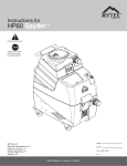
CR-50XP
Cornerounder
R
USER’S MANUAL
Before operating this equipment, please read these
instructions completely and keep these operating
instructions for future reference.
Serial Number:
Date of Purchase:
Dealer:
Address:
Telephone Number:
485 Hague Street, Rochester, NY 14606 U.S.A.
Tel: 585-436-1934
Fax: 585-464-8665
www.lasscowizer.com
[email protected]
Table Of Contents
1 - Introduction
1.1
1.2
Your New CR-50XP.............................. Page 01
Shipping Damage Inspection............... Page 01
2 - Safety
2.1
2.2
Safety Instructions................................ Page 02
Warning Labels..................................... Page 03
3 - Setting Up Your Machine
3.1
3.2
3.3
3.4
3.5
3.6
3.7
3.8
Loose Items Inventory.......................... Page 03
Installing the Leveling Feet.................. Page 04
Foot Pedal Guard................................. Page 04
Preparing the Regulator System.......... Page 05
Cutting Unit Installation (Standard &
Special Sizes)....................................... Page 06
Cutting Unit Installation (Large Sizes).. Page 07
Adjusting the Side Guides.................... Page 07
Adjusting the Pressure Foot................. Page 08
4 - Operation
4.1
4.2
4.3
Corner Rounding Operation................. Page 08
Cutting Unit Capacities......................... Page 08
Chip Removal....................................... Page 08
5 - Maintenance
5.1
5.2
Safety.................................................... Page 09
Annual Lubrication............................... Page 09
1 - Introduction
1.1 - Your New CR-50XP
Thank you for your purchase of the CR-50XP
Cornerounder .
R
We ask that you take a moment to fill in the serial
number and other information on the front cover of the
manual. Please keep this manual as a reference for
future use.
For parts and service, please contact the Lassco-Wizer
Dealer from whom you purchased the machine. If you
require assistance in locating a Lassco-Wizer Dealer
please contact our customer service department at 585436-1934. Please have the model of your machine and
the serial number when you call.
If you wish to write to us, send correspondence to:
Lassco-Wizer
Attn: Customer Service
485 Hague Street
Rochester, NY 14606
1.2 - Shipping Damage Inspection
Remove the machine from the carton and inspect for
any shipping damage. If any damage is present, report
the damage to the carrier immediately; failure to do so
may void any warranties.
6 - Parts Diagram
6.1
6.2
Parts Diagram....................................... Page 09
Parts List.............................................. Page 10
Page 01
2 - Safety
2.1 - Safety Instructions
All operators must read and understand the Users
Manual including all safety instructions before using this
equipment. Failure to fully understand the safety
instructions can result in personal injury. If after reading the
manual you are still uncertain about use, please
contact the dealer from whom you purchased the
machine for assistance. If you need contact information for
a Service Technician nearest you please call
585-436-1934.
SAFETY OF THIS EQUIPMENT IS THE RESPONSIBILITY
OF THE USER(S).
CHECK DAMAGED PARTS. Before further use of the machine, a guard or other part that is damaged should be carefully checked to determine that it will operate properly and
perform its intended function--check for alignment of moving
parts, binding of moving parts, breakage of parts, mounting, and any other conditions that may affect its operation.
A guard or other part that is damaged should be properly
repair or replaced.
NEVER LEAVE MACHINE RUNNING UNATTENDED.
TURN POWER OFF. Don’t leave machine until it comes to
a complete stop.
Please read and follow all warning labels on your machine.
Keep hands clear while operating machine.
ALWAYS USE SAFETY GLASSES. Everyday eyeglasses
only have impact resistant lenses, they are NOT safety
glasses.
KEEP GUARDS IN PLACE and in working order.
Always disconnect the power before servicing this machine.
Service should only be performed by a QUALIFIED TECHNICIAN.
THIS MACHINE IS DESIGNED FOR ONE PERSON OPERATION. Never operate the machine with more than one
person.
KEEP CHILDREN AWAY. All visitors should be kept a safe
distance from the work area.
USE RIGHT MACHINE. Don’t force tool or attachment to
do a job for which it was not designed.
MAINTAIN MACHINE WITH CARE. Keep tools sharp and
clean for best and safest performance. Follow instructions
for lubricating and changing accessories.
DISCONNECT MACHINE when changing accessories,
such as cutting units.
REDUCE THE RISK OF UNINTENTIONAL STARTING.
Make sure the air valve shutoff is in the off position when
the machine is not in use.
NEVER STAND ON MACHINE. Serious injury could occur
if the machine is tipped.
Page 02
2 - Safety
2.2 - Warning Labels
English
French
3 - Setting Up Your Machine
3.1 - Loose Items Inventory
Please remove and inspect the following items:
Oil
Foot Pedal Guard (1)
Pressure Gauge (1)
10-32 x 1/2” Button Head
Socket Screw (2)
1/8” Hex Wrench (1)
Page 03
3 - Setting Up Your Machine
3.2 - Installing the Leveling Feet
3.2.1
Set the machine down in its desired location and determine if the
machine is level, making sure that it does NOT rock in any direction. If it does, determine which Leveling Feet need to be adjusted
and whether they need to be adjusted up or down.
3.2.2
If adjustment is needed, start by loosening the four (4) nuts which
are accessed through the rear of the machine.
3.2.3
Next adjust the four (4) Leveling Feet by screwing them clockwise
to raise the or counter-clockwise to lower. After each adjustment
set the machine down completely to verify that the machine no
longer rocks. Continue adjustment as needed until the machine
sits securely in place. Tighten the four (4) nuts down to secure the
position of the Leveling Feet.
Nut
Leveling Feet
Base of the Machine
3.3 - Foot Pedal Guard
3.3.1
Attach the orange Foot Pedal Guard to the base of the machine so that it covers the Foot Pedal protecting it from
accidental activation. Use the two 10-32 x1/2” Button Head Socket Screws. Tighten down using the 1/8” Hex
Wrench (provided).
Foot Pedal
Foot Pedal Guard
Base of the Machine
10-32 x 1/2” Button Head Socket Screw
1/8” Hex Wrench
Page 04
3 - Setting Up Your Machine
3.4 - Preparing the Regulator System
3.4.1
Attach the Pressure Gauge to the Air Regulator by screwing it in as shown below. The threads on the Pressure Gauge
have Teflon tape attached to prevent air leakage. Tighten down using a 7/16” opened ended wrench (not provided).
3.4.2
Add the provided oil to the Airline Lubricator located on the side of the machine by removing the slotted Set Screw and
filling the Lubricator so as to cover the bottom of the brass Oil Intake Tube visible inside the globe as shown below.
Replace the Set Screw making sure the Set Screw Washer is positioned correctly.
3.4.3
Install the Airline into the Air Valve Shutoff on the side of the machine screwing it in place. DO NOT overtighten.
It is recommended that you hold the Air Valve Shutoff securely while attaching the Airline to prevent damage.
3.4.4
Rotate the Air Valve Shutoff counter-clockwise to allow air passage into the machine. To stop the passage of air to the
machine rotate the Air Valve Shutoff clockwise.
3.4.5
Adjust the Pressure Gauge to 80 PSI for normal performance. Adjust by either turning the Pressure Adjustment Knob
counter clockwise to raise the PSI or clockwise to lower the PSI.
Set Screw
Set Screw Washer
Air Valve Shutoff
OFF
Oil
ON
Filter Regulator
Oil Lubricator
Airline
Pressure Gauge
Oil Intake Tube
Pressure Adjustment Knob
Air Regulator
Set Screw
Airline
LBS / SO
IN
Pressure Gauge (Set to 80 PSI)
Oil Intake Tube
Oil (Correct oil level)
Page 05
3 - Setting Up Your Machine
3.5 - Cutting Unit Installation (Standard & Special Sizes)
3.5.1
Loosen the Top Yoke Wing Nut (50-34) on the right hand side of the Top Yoke (50-15) and swing the Top Yoke
toward you to obtain access to the Cutting Unit Cavity in the Table Ring Casting (50-14).
3.5.2
Making sure the Adapter Hold Down Tab (50-11) is not in the way, insert the Adapter Plate (50-26) into the Table
Ring Casting. Make sure that the Adapter Plate Rotation Tab (50-12) slips under the Table Ring Casting into its
designated groove to prevent unwanted rotation of the Adapter Plate. Turn the Adapter Hold Down Tab so that it
locks the Adapter Plate into place.
3.5.3
Insert the Cutting Unit into the Adapter Plate.
3.5.4
Swing the Top Yoke back into its original position making sure it is fully engaged in the Yoke Slide Rod (50-04).
Tighten down the Top Yoke Wing Nut to secure in place.
3.5.5
Depress the Foot Pedal to engage the cutting cycle making sure to check that the Cutting Unit is working
properly.
Standard / Special Size
Cutting Unit (Misc Part #)
Adapter Plate (50-26)
Adapter Plate Roation Tab (50-12)
Adapter Hold Down Tab (50-11)
Top Yoke Wing Nut (50-34)
Pressure Foot Assembly
(50-201A)
Yoke Slide Rod (50-04)
Cutting Unit Cavity
Top Yoke (50-15)
Side Guide (50-03R)
Wood Table (50-29)
Side Guide (50-03L)
Table Ring Casting (50-14)
Page 06
3 - Setting Up Your Machine
3.6 - Cutting Unit Installation (Large Sizes)
3.6.1
Loosen the Top Yoke Wing Nut (50-34) on the right hand side of the Top Yoke (50-15) and swing the Top Yoke as
shown to obtain access to the Cutting Unit Cavity in the Table Ring Casting (50-14).
3.6.2
Make sure the Adapter Plate has been removed.
3.6.3
Insert the Large Size Cutting Unit into the Table Ring Casting by tilting and seating it and pushing back and down
until it is secure in place. Make sure the Rotation Tab on the Cutting Unit slips under the Table Ring Casting into
its designated groove to prevent unwanted rotation of the Cutting Unit. Turn the Adapter Hold Down Tab (50-11)
so that it locks the Cutting Unit into place.
3.6.4
Swing the Top Yoke back into its original position making sure it is fully engaged in the Yoke Slide Rod (50-04).
Tighten down the Top Yoke Wing Nut to secure in place.
3.6.5
Depress the Foot Pedal to engage the cutting cycle making sure to check that the Cutting Unit is working
properly.
Large Cutting Unit
(Misc Part #)
Rotation Tab
Adapter Hold Down Tab (50-11)
Top Yoke Wing Nut (50-34)
Pressure Foot Assembly
(50-201A)
Yoke Slide Rod (50-04)
Cutting Unit Cavity
Top Yoke (50-15)
Side Guide (50-03R)
Wood Table (50-29)
Side Guide (50-03L)
Table Ring Casting (50-14)
3.7 - Adjusting the Side Guides
3.7.1
Adjust the Side Guides so that they are square with the cutting unit you are using. We recommend using a right
angle tool (not included).
3.7.2
Slide the tool into the corner of the Cutting Unit making sure it is square with both edges of the Knife.
3.7.3
Loosen the Screws on the Side Guides and adjust as needed. Re-tighten the screws to secure the Side Guides.
Page 07
3 - Setting Up Your Machine
3.8 - Adjusting the Pressure Foot
3.8.1
To adjust horizontally (depending on the size of the Cutting Unit)
loosen the center Thumb Screw on the Top Yoke, adjust in or out
until the Pressure Foot clears the black guard on the Cutting Unit.
Secure by tightening the center Wing Nut down.
Wing Nut
Hex Nut
Thumb
Screw
E-clip
3.8.2
Adjust the Pressure Foot clamping pressure to accommodate different product heights. Loosen the Wing Nut on the top of the
Pressure Foot. Tighten the Hex Nut underneath to increase the
pressure Loosen the Hex Nut to decrease pressure. When the
pressure is set as desired tighten down the Wing Nut to lock the
tension in place.
Pressure Foot
Top Yoke
4 - Operation
4.1 - Corner Rounding Operation
4.1.1
Place the product you are cutting onto the Wooden Top Plate and push it into the corner aligning it with the Two Side
guides.
4.1.2
Press down firmly to prevent the product from sliding out of the corner.
4.1.3
Depress the Foot Pedal once to engage the cutting cycle. The Pressure Foot will come down helping to secure the
product in place. The Cutting Unit will come down.
4.1.4
Release the Foot Pedal once the cutting unit has come down all the way. The cutting unit will return to its upright
position. This machine does not cycle.
4.1.5
Repeat as needed
4.1.6
It may be necessary to adjust the Side Guides to compensate for variation in the cutting unit geometry, especially
when changing from a Standard / Special Size Cutting Unit to a Large Size Cutting Unit.
4.2 - Cutting Unit Capacities
4.2.1
Standard / Special Size Cutting Units:
These size Cutting Units were designed to handle up to a 1/2” stack of paper. They will also cut many other materials
such as plastics, cardboard, celluloid, leather, wood, and even light soft metals. With heavier materials, however,
best results may be obtained if only one or a few pieces are cut at a time.
4.1.2
Large Size Cutting Units:
These size Cutting Units were designed to handle up to a 1/8” stack of paper. They will also cut many other materials such as plastics, cardboard, celluloid, leather, and wood. With heavier materials, however, best results may be
obtained if only one or a few pieces are cut at a time.
4.3 - Chip Removal
4.3.1
Place a waste bin or a disposable basket underneath the Chip Chute on the rear of the machine. This will catch the
chips as they are cut and slide down the Chip Chute. Empty as needed.
Page 08
5 - Maintenance
5.1 - Safety
ALWAYS TURN OFF AND DISCONNECT THE AIR SUPPLY BEFORE PERFORMING MAINTENANCE ON THIS MACHINE. MAINTENANCE SHOULD ONLY BE
PERFORMED BY A QUALIFIED TECHNICIAN.
KEEP HANDS CLEAR WHILE PERFORMING MAINTENANCE ON THIS MACHINE.
MOVING PARTS CAN CRUSH AND CUT.
5.2 - Annual Lubrication
5.2.1
Lightly oil the two Yoke Slide Rods where they enter the adapter ring approximately every two weeks or as needed
depending on use.
5.2.2
Maintain, as needed, an oil level in the Oil Lubricator so that oil is covering the bottom of the Pickup Tube inside the
globe. If oil appears around the Foot Valve, the lubrication rate is excessive and can be dimminished by turning
the knob on top of the Lubricator clockwise.
6 - Parts Diagram
6.1 - Parts Diagram
Foot Pedal
Page 09
6 - Parts Diagram
6.2 - Parts List
50-26: Adapter Plate
50-12: Adapter Plate Rotation Tab
50-15: Top Yoke
50-201A: Pressure Foot Assembly
50-03L: Left Paper Guide (50-03R: Right Paper Guide Not Shown)
50P-80: Wood Table
50-04: Yoke Slide Rods
50P-41: Bottom Yoke
50XP-2010: Pull Rod
50XP-600AB: Upper Chip Chute
50XP-40: Back
50XP-2006: Air Cylinder
FMP2-2007: Air Hose (x3)
FMP2-2004: Foot Pedal
FMP2-2010: Elbow (x2 not shown)
FMP2-2002: Stationary Muffler
FMP2-2003: Adjustable Muffler
Page 10