1
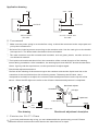
Application drawing
Vcc+
Vcc+ Vdd+
R1
R1
OUTPUT
OUTPUT
GND
Vcc=5V Vdd=5-24V
R1=10K
GND
VCC=Vdd=5V
R1=10K
Ⅳ. User manual
① Make sure the power wiring is correct before using. It should be connected to the output part and
pull up the resistance R1 .
② Surface of the inducing sensor must cling to the container side. Use the resin glue or the double
side tape to fix. The down-lead is fetched out from netherward.
③ The used container must be nonmetal and insulated, such as glass, plastic, ceramic and so on
non-dielectric material.
④ The liquid level benchmark should lie in the centeraline of the vertical direction of the inducing
sensor during installation. After installation, the working liquid level ON/OFF should deviate within
10mm. If go beyond the requirement, use the special tool to adjust again.
⑤ Benchmark adjustment method
Surface of the inducing of the sensor clings to the container side and the liquid level lies in the
centerline of the vertical direction of the inducing sensor. Take away the QC label, Use a
irresponsive screwdriver to adjust the resistor inside the adjustment hole on the top-left of the
sensor. When the LED light turns on from the off state that means adjustment is completed.
12
37
Benchmark adjuster
30
Screwdriver
LED light
50
Liquid level
1/2H=25mm
L= 400
1100
Size drawing
Output
Units: mm
Benchmark adjustment description
Ⅴ. Exterior size 50×37×12mm
Ⅵ. If you have problems during using, you can't disassemble the products by yourself. Please
dismantle the entire sensor and return back to the manufacturer to repair.