1
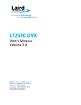
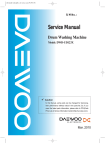
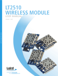
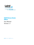
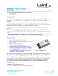
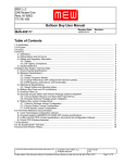
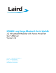
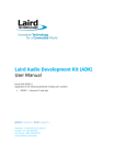
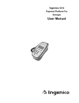
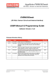
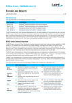
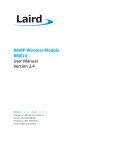
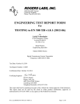
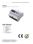
Transitioning from LT2510 to RM024 v1.0 INTRODUCTION The RM024 is the first new module in Laird’s rebranded RAMP (Range Amplifi ED MULTIPOINT) LINE OF MODULES. Laird’s RAMP modules excel at providing a wireless serial link over long ranges and with support for multipoint networks. RAMP modules utilize a Frequency Hopping Spread Spectrum (FHSS) protocol for greater interference and multipath immunity. With two transceivers, the RAMP line can provide a wireless serial cable replacement capable of extending communications well beyond the 50 foot maximum for wired connections. RAMP modules also support multipoint – Star network topologies – and users can employ a nearly unlimited number of clients for applications such as sensors, controls, and text display boards. The RM024 is based on the same core technology as the LT2510 and is designed to be a drop in replacement. Differences between the modules may affect customer designs; this document IDENTIFIES THESE differences. ThE RM024 AND THE LT2510 ARE OVER-THE-air compatible and can both be used in the same network. PART NUMBERS LT2510 Part Number RM024 Part Number Form Factor Maximum TX Power Antenna EEPROM Product ID PRM110 PRM111 PRM120 PRM121 PRM112 PRM113 PRM122 PRM123 RM024-S125-C-01 RM024-S125-M-01 RM024-P125-C-01 RM024-P125-M-01 RM024-S50-C-01 RM024-S50-M-01 RM024-P50-C-01 RM024-P50-M-01 SMT SMT Pluggable Pluggable SMT SMT Pluggable Pluggable 125 mW 125 mW 125 mW 125 mW 50 mW (CE) 50 mW (CE) 50 mW (CE) 50 mW (CE) u.FL Jack Chip Antenna u.FL Jack Chip Antenna u.FL Jack Chip Antenna u.FL Jack Chip Antenna RM024125C01 RM024125M01 RM024125C01 RM024125M01 RM02450C01 RM02450M01 RM02450C01 RM02450M01 SPECIFICATIONS Detailed Specifications LT2510 RM024 SMD-ANT, SMD-U.FL, Pluggable-ANT, Pluggable-U.FL Integrated chip antenna or external antenna through U.FL connector SMD-U.FL, Pluggable-U.FL, SMD-ANT+U.FL, Pluggable-ANT+U.FL External antenna through U.FL connector or both U.FL and integrated chip antenna FCC: +11 to +21 dBm selectable CE: +8 to +17 dBm selectable 3.3V – 3.6V ± 50 mV ripple FCC: +5 to +21 dBm selectable CE: +3.5 to +17 dBm selectable 2.3 – 3.6V ± 50 mV ripple General Form Factor Antenna Transceiver Output Power 2 Conducted Supply Voltage Americas: +1-800-492-2320 Option 2 Europe: +44-1628-858-940 Hong Kong: +852-2923 0610 www.lairdtech.com/bluetooth 1 CONN-APPNOTE-RM024_TransistioningfromLT2510 Transitioning from LT2510 to RM024 Application Note LT2510 RM024 100% Tx 1/8 Tx (when selected) 100% Rx Rx Average (idle current) Deep Sleep Current Draw Receiver Sensitivity (1% PER) Range (based on external 2.5 dBi antenna at 280 5 kbps RF data rate) 190 mA 40 mA 40 mA 85 mA 40 mA 40 mA 10 mA 10 mA 50 µA 50 µA -95 dBm at 280 kbps RF data rate4 -94 dBm at 500 kbps RF data rate FCC CE 100% Tx 1/8 Tx (when selected) 100% Rx Rx Average (idle current) Deep Sleep 166 mA 40 mA 36 mA 85 mA 40 mA 36 mA 9.5 mA 11.6 mA 50 µA 50 µA -95 dBm at 280 kbps RF data rate -94 dBm at 500 kbps RF data rate Outdoor Indoor Outdoor Indoor (line of sight) (estimated) (line of sight) (estimated) 4 km (2.5 miles) 2.4 km (1.5 miles) 400 m (1300 feet) 240 m (790 feet) 4 km (2.5 miles) 2.4 km (1.5 miles) 400 m (1300 feet) 240 m (790 feet) FCC CE 6 Physical SMD-ANT and SMDBoth Dimensions SMD-U.FL Dimensions Pluggable-ANT and Pluggable-Both Dimensions Pluggable-U.FL Dimensions Certifications FCC Part 15.247 Industry Canada (IC) CE RoHS Japan Brazil (Anatel) 1 25.4 x 39 x 3.6 mm (1.0 x 1.54 x 0.14 in.) 24.3 x 32.4 x 3.6 mm (1.0 x 1.28 x 0.14 in.) 25.4 x 39 x 3.6 mm (1.0 x 1.54 x 0.14 in.) 25.4 x 32.4 x 3.6 mm (1.0 x 1.28 x 0.14 in.) 24.3 x 36 x 10.3 mm (0.96 x 1.42 x 0.406 in.) 26.7 x 39.6 x 11.3 mm (1.05 x 1.56 x 0.44 in.) 24.3 x 30.1 x 10.3 mm (0.96 x 1.185 x 0.406 in.) 26.7 x 33 x 10.6 mm (1.05 x 1.29 x 0.42 in. KQL-2510100P KQL-2510100P 2268C-2510100P 2268C-2510100P N/A EN 300 328-2 V1.71,EN 301 489 Yes PRM122: 005WWCA0358 PRM123: 005WWCA0359 3000-10-6625 No TBD TBD TBD Yes TBD None 1. Contact your sales representative for more details. 2. Maximum Output power stated, step measurements for power could vary by +/- 1.5 dBm. Step downs on RM024 are larger than on LT2510, resulting in lower Maximum Power for each step. 3. Sleep current is estimated. 4. Estimated. Measurements were taken at 4.1 miles with 5 dBi antenna. 5. RX Sensitivity is listed at -98 dBm in the LT2510 User Manual, restated here based on new measurements. 6. Physical Dimensions are estimated, actual measurements are printed in Mechanical Drawings section of this document. Americas: +1-800-492-2320 Option 2 Europe: +44-1628-858-940 Hong Kong: +852-2923-0610 [email protected] www.lairdtech.com/ramp 2 CONN-APPNOTE_TransitionfromLT2510 Transitioning from LT2510 to RM024 Application Note PIN FUNCTION CHANGES No pins change function. EEPROM ADDRESS CHANGES The following EEPROM addresses are different on the RM024 EEPROM Addresses Notes LT2510 Name RM024 Name LT2510 Description RM024 Description 0x00 – 0x23 Product ID is changing to reflect new RM024 part number Product ID Product ID Product identifier string; includes revision information for software and hardware. Product identifier string; includes revision information for software and hardware. 0x90 – 0x9F Part number is changing to reflect new RM024 part number Part Number Part Number Factory set part number for the unit Factory set part number for the unit 0xC1, Bit 5 This bit has been repurposed. In LT2510, this bit enabled sleep timer calibration. In RAMP modules, the sleep timer is constantly undergoing calibration, so this bit is no longer required. Sleep Calibration Enabled Antenna Select Bit-5: Sleep Calibration Enable Selects which antenna port is to be used. 0 = Disable 0 == Antenna Port 1 = Enable 2 (Black Chip) 1 == Antenna Port The Antenna Select EEPROM bit is loaded at boot on the RMO24 1 (u.FL) AT COMMANDS The following is a new AT command for Antenna Select on the RM024: Antenna Switch Command: Command sets the antenna port for the transceiver to use. Command: <0xCC><0x26><Port Select> Response: <0xCC><0x26><Port Select> Port Select: Antenna Port 2 == 0x00 (Integrated Antenna) Antenna Port 1 == 0x01 (U.FL Port) Americas: +1-800-492-2320 Option 2 Europe: +44-1628-858-940 Hong Kong: +852-2923-0610 [email protected] www.lairdtech.com/ramp 3 CONN-APPNOTE_TransitionfromLT2510 Transitioning from LT2510 to RM024 Application Note REGULATORY INFORMATION FCC Due to changes to the key components of the radio frequency (RF) Path, the RM024 carries a different regulatory approval number, model number, and test reports. Customers are recommended to have a qualified test lab perform FCC Part 15 Subpart B unintentional radiator testing on their device to make sure that it continues to be in compliance with the emission limits for either a Class A or B digital device. In addition, customers must update label information on their product with the new FCC and IC identification numbers and must update their user manuals and other documentation to reflect the new regulatory information. CE A new Declaration of Conformity will be issued for the RM024. Customers must update their Declaration of Conformity to reflect new reports that we issue. MECHANICAL DRAWINGS The form factor of the surface mount integrated antenna versions of the RM024 and LT2510 are the same. Customers using the U.FL version of the SMT module can either purchase the new integrated antenna version and use the new onboard U.FL or purchase a U.FL-only version directly from Laird. The form factor of the RM024 pluggable module is slightly larger than the LT2510; see Figures 1 – 6 for details. Note on Mechanical Drawings: All dimensions are in millimeters. PC board material is 0.79 mm thick FR4. Provide clearance of at least 1.5 mm around the module to be free of other components and features. Module should not exceed 260°C during reflow soldering. Americas: +1-800-492-2320 Option 2 Europe: +44-1628-858-940 Hong Kong: +852-2923-0610 [email protected] www.lairdtech.com/ramp 4 CONN-APPNOTE_TransitionfromLT2510 Transitioning from LT2510 to RM024 Application Note Figure 1: SMT LT2510 with Integrated Antenna (PRM111, PRM113) Americas: +1-800-492-2320 Option 2 Europe: +44-1628-858-940 Hong Kong: +852-2923-0610 [email protected] www.lairdtech.com/ramp 5 CONN-APPNOTE_TransitionfromLT2510 Transitioning from LT2510 to RM024 Application Note Figure 2: SMT LT2510 with U.FL (PRM110, PRM112) Americas: +1-800-492-2320 Option 2 Europe: +44-1628-858-940 Hong Kong: +852-2923-0610 [email protected] www.lairdtech.com/ramp 6 CONN-APPNOTE_TransitionfromLT2510 Transitioning from LT2510 to RM024 Application Note Figure 3: Pluggable LT2510 with Antenna (PRM121, PRM123) Americas: +1-800-492-2320 Option 2 Europe: +44-1628-858-940 Hong Kong: +852-2923-0610 [email protected] www.lairdtech.com/ramp 7 CONN-APPNOTE_TransitionfromLT2510 Transitioning from LT2510 to RM024 Application Note Figure 4: Pluggable LT2510 with U.FL (PRM120, PRM122) Americas: +1-800-492-2320 Option 2 Europe: +44-1628-858-940 Hong Kong: +852-2923-0610 [email protected] www.lairdtech.com/ramp 8 CONN-APPNOTE_TransitionfromLT2510 Transitioning from LT2510 to RM024 Application Note Figure 5: SMT RM024 (RM024-SXX-M-01) Americas: +1-800-492-2320 Option 2 Europe: +44-1628-858-940 Hong Kong: +852-2923-0610 [email protected] www.lairdtech.com/ramp 9 CONN-APPNOTE_TransitionfromLT2510 Transitioning from LT2510 to RM024 Application Note Figure 6: Pluggable RM024 (RM024-PXXX-M-01) Americas: +1-800-492-2320 Option 2 Europe: +44-1628-858-940 Hong Kong: +852-2923-0610 [email protected] www.lairdtech.com/ramp 10 CONN-APPNOTE_TransitionfromLT2510 Transitioning from LT2510 to RM024 Application Note PHYSICAL APPEARANCE Figure 8: Surface Mount LT2510 Figure 7: Surface Mount RM024 REVISION HISTORY Revision Date 1.0 17 Dec 2013 Description Initiated By Initial Release Americas: +1-800-492-2320 Option 2 Europe: +44-1628-858-940 Hong Kong: +852-2923-0610 [email protected] www.lairdtech.com/ramp Chris Downey 11 CONN-APPNOTE_TransitionfromLT2510