1
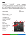
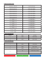
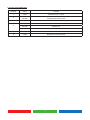
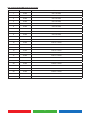
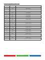
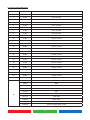
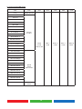
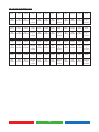
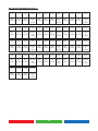
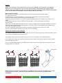
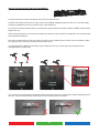
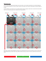
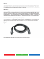
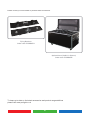
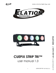
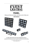
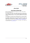
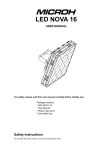
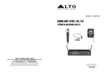
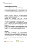
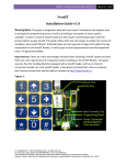
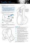
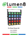
Tri Pixel Panel 25
Code: ELUM085
USER MANUAL
1
IMPORTANT:
The manufacturer will not accept liability for any resulting damages caused
by the non-observance of this manual or any unauthorised modification to the
equipment.
• Never let the power-cable come into contact with other cables. Handle the power-cable
and all mains voltage connections with particular caution!
• Never remove warning or informative labels from the equipment.
• Do not open the equipment and do not modify the equipment.
• Do not connect this equipment to a dimmer-pack.
• Do not switch the equipment on and off in short intervals, as this will reduce the
system’s life.
• Only use the equipment indoors.
• Do not expose to flammable sources, liquids or gases.
• Cleaning must be done at regular intervals.
• Before cleaning, wait until the unit has cooled.
• Use a vacuum or dry compressed air and a soft brush to remove the dust collected on the
external vents and accessible internal components.
• Clean the external surfaces with a mild solution of non-ammonia glass cleaner or
isopropyl alcohol and wipe with a soft, lint free cotton cloth or lense cleaning tissue.
• Always disconnect the power from the mains when equipment is not in use or before
cleaning! Only handle the power-cable by the plug. Never pull out the plug by pulling the
power-cable.
• Make sure that the available voltage is between 100V-240V.
• Make sure that the power-cable is never crimped or damaged. Check the equipment and
the power-cable periodically.
• If the equipment is dropped or damaged, disconnect the mains power supply immediately.
Have a qualified engineer inspect the equipment before operating again.
• If the equipment has been exposed to drastic temperature fluctuation (e.g. after
transportation), do not switch it on immediately. The arising condensation might damage
the equipment. Leave the equipment switched off until it has reached room temperature.
• If your product fails to function correctly, discontinue use immediately. Pack the unit
securely (preferably in the original packing material), and return it to your Prolight dealer
for service.
• Only use fuses of same type and rating.
• Repairs, servicing and power connection must only be carried out by a qualified
technician. THIS UNIT CONTAINS NO USER SERVICEABLE PARTS.
• WARRANTY; One year from date of purchase.
• eLumen8 products are designed and intended for professional use only by competant
persons. The products are not suitable for domestic use.
OPERATING DETERMINATIONS
If this equipment is operated in any other way, than those described in this manual,
the product may suffer damage and the warranty becomes void.
Incorrect operation may lead to danger e.g.: short-circuit, burns, electric shocks,
LED failure etc.
Do not endanger your own safety and the safety of others!
Incorrect installation or use can cause serious damage to people and property.
2
Overview:
You should find inside the elumen8 carton the following items:
1, Tri Pixel Panel 25 2, Instruction manual, 3, Power Cable
4, Bracket & fixings
The Tri Pixel Panel 25 offers full pixel map technology within a rugged chassis featuring rigging and array options
to allow lighting designers to create stunning effects. 30W COB tri-colour LEDs deliver a full spectrum of colours,
and has a wide range of built-in DMX personalities to simplify integration and compatibility with a wide range of
DMX consoles.
Note: The Tri Pixel Panel 25 is designed for use as a pixel mappable effect. Due to the density of high power of
the LED’s onboard the fixture is not intended for use at full intensity over extended periods, doing do may shorten
the lifespan of the COB LEDs. To ensure effective cooling the Tri Pixel Panel 25 should be mounted in free space
with 300mm or greater of clearance behind the fixture to allow for sufficient airflow and cooling.
Technical Specifications:
Operating modes: • 25 x 30W tri-colour LEDs
• Beam angle: 80 degrees
• 1100Hz refresh rate
• 0-100% dimming and variable strobe
• DMX channels: 3/5/6/25C/25W/26/75/76/78 or 100
selectable
• Sound active, auto, master/slave, built-in programmes and DMX modes
• 4 push button menu with LCD display
• Powercon in/out sockets
• 3-Pin XLR in/out sockets
• 5-pin XLR in/out sockets
• Individually addressable LEDs
• Fan cooled
• Quarter turn quick lock rigging system
• Power consumption: 780W
• Power supply: 100-240V~50Hz-60Hz
• Dimensions: 550 x 130 x 550mm
• Weight: 18.5kg
Identification:
1, Safety eyes
2, Power in socket
3, Power out socket
4, Flying bracket (ELUM085A)
5, Fuse (F4A~250V/F8A~120V)
6, 3-pin XLR in socket
7, 3-pin XLR out socket
8, 5-pin XLR in socket
9, 5-pin XLR out socket
10, Microphone
11, Cooling fan
12, Function buttons
13, Coffin locks
14, LCD display
3
1, Sound active
2, Auto
3, Master/slave
4, Built-in programmes
5, DMX
Operation modes:
Sound Active mode:
To activate the unit in sound active mode, press the “MODE” button to show “SOUND MODE” on the LCD
screen. Now press the “SET UP” button to select the desired sensitivity level by using the “UP” and “DOWN”
buttons. Press the “SET UP” button again to select the frequency level and adjust by using the “UP” and
“DOWN” buttons.
“SENS” 00 - 31 (00 = low, 31 = high)
“FQN” 01-99 (01 = low, 99 = high)
Auto run mode:
To activate the unit in auto run mode, press the “MODE” button to show “AUTO RUN” on the LCD screen. Now
press the “SET UP” button to select the desired frequency level by using the “UP” and “DOWN” buttons.
“FQN” 01-99 (01 = low, 99 = high)
Note: In this mode, it will run 14 built-in programmes in a continuous loop.
Slave mode:
To activate the unit in slave mode, first you must link multiple units together and press the “MODE” button to
show “SLAVE MODE” on the LCD screen. Now on the master unit press the “MODE” button to select the
desired mode and the slave units will now run in sequence with the master unit.
Built-in programmes:
To activate the units built-in programmes, press the “MODE” button to show “01.STATIC” on the LCD screen.
Press the “SET UP” button to choose between the 14 built-in programmes by using the “UP” and “DOWN”
buttons. Now press the “SET UP” button to select the desired speed and adjust by using the “UP” and
“DOWN” buttons. Press the “SET UP” button once more to select the desired flash value and adjust by using
the “UP” and “DOWN” buttons.
Speed values: 00 - 99 (00 = slow, 99 = fast)
Flash values: 00 - 99 (00 = slow, 99 = fast)
For the 14 built-in programmes please see page 5.
DMX mode:
To activate the unit in DMX mode, press the “MODE” button to show “DMX MODE” on the LCD screen. Press
the “SET UP” button and select the desired DMX address setting by using the “UP” and “DOWN” buttons.
Then to select one of the DMX modes 3/5/6/25C/25W/26/75/76/78 or 100 channel, press the “SET UP” button
again to choose the desired DMX mode by using the “UP” and “DOWN” buttons.
For the 3/5/6/25C/25W/26/75/76/78 or 100 channel DMX address information please see pages overleaf.
4
14 Built-in programme chart:
Static colour
BLAC-RGB Flash 00-99
Blackout, red, yellow, green, cyan, blue, purple, white
Flash speed adjustable
Dream
Speed 00-99 Fash 00-99
7 colour dreaming
Speed & flash adjustable
Meteor
Speed 00-99 Flash 00-99
7 colour flow
Speed & flash adjustable
Fade
Speed 00-99 Flash 00-99
7 colour fade
Speed & flash adjustable
Change
Speed 00-99 Flash 00-99
7 colour change
Speed & flash adjustable
Flow 1
Speed 00-99 Flash 00-99
7 colour chase
Speed & flash adjustable
Flow 2
Speed 00-99 Flash 00-99
7 colour chase
Speed & flash adjustable
Flow 3
Speed 00-99 Flash 00-99
7 colour chase
Speed & flash adjustable
Flow 4
Speed 00-99 Flash 00-99
7 colour chase
Speed & flash adjustable
Flow 5
Speed 00-99 Flash 00-99
7 colour chase
Speed & flash adjustable
Flow 6
Speed 00-99 Flash 00-99
7 colour chase
Speed & flash adjustable
Flow 7
Speed 00-99 Flash 00-99
7 colour chase
Speed & flash adjustable
Flow 8
C1: RGB C2: RGB
7 colour chase
Speed & flash adjustable
Flow 9
C1: RGB C2: RGB
7 colour chase
Speed & flash adjustable
3 channel mode DMX chart:
Channel
Value
Functions
1
0-255
Red 0-100%
2
0-255
Green 0-100%
3
0-255
Blue 0-100%
5 channel mode DMX chart
Channel
Value
Functions
1
0-255
Red 0-100%
2
0-255
Green 0-100%
3
0-255
Blue 0-100%
4
0-255
Master dimmer 0-100%
5
0
No function
1-5
Sound active (7 colours)
6-10
No function
11-255
Strobe (slow to fast)
5
6 channel mode DMX chart:
Channel
Value
Function
1
0-255
Master dimmer 0-100%
2
0-149
150-255
Static Pattern
Moving Pattern slow to fast
3
0-149
Patern selector
4
0-99
Letters A-Z
100-199
Numbrs 1-9
200-255
Patterns
5
0-255
Pattern colour selector
6
0-255
Background colour selector
6
25C channel mode DMX chart (Cool white):
Channel
Value
Function
1
0-255
Cell 1 0-100%
2
0-255
Cell 2 0-100%
3
0-255
Cell 3 0-100%
4
0-255
Cell 4 0-100%
5
0-255
Cell 5 0-100%
6
0-255
Cell 6 0-100%
7
0-255
Cell 7 0-100%
8
0-255
Cell 8 0-100%
9
0-255
Cell 9 0-100%
10
0-255
Cell 10 0-100%
11
0-255
Cell 11 0-100%
12
0-255
Cell 12 0-100%
13
0-255
Cell 13 0-100%
14
0-255
Cell 14 0-100%
15
0-255
Cell 15 0-100%
16
0-255
Cell 16 0-100%
17
0-255
Cell 17 0-100%
18
0-255
Cell 18 0-100%
19
0-255
Cell 19 0-100%
20
0-255
Cell 20 0-100%
21
0-255
Cell 21 0-100%
22
0-255
Cell 22 0-100%
23
0-255
Cell 23 0-100%
24
0-255
Cell 24 0-100%
25
0-255
Cell 25 0-100%
7
25W channel mode DMX chart (Warm white):
Channel
Value
Function
1
0-255
Cell 1 0-100%
2
0-255
Cell 2 0-100%
3
0-255
Cell 3 0-100%
4
0-255
Cell 4 0-100%
5
0-255
Cell 5 0-100%
6
0-255
Cell 6 0-100%
7
0-255
Cell 7 0-100%
8
0-255
Cell 8 0-100%
9
0-255
Cell 9 0-100%
10
0-255
Cell 10 0-100%
11
0-255
Cell 11 0-100%
12
0-255
Cell 12 0-100%
13
0-255
Cell 13 0-100%
14
0-255
Cell 14 0-100%
15
0-255
Cell 15 0-100%
16
0-255
Cell 16 0-100%
17
0-255
Cell 17 0-100%
18
0-255
Cell 18 0-100%
19
0-255
Cell 19 0-100%
20
0-255
Cell 20 0-100%
21
0-255
Cell 21 0-100%
22
0-255
Cell 22 0-100%
23
0-255
Cell 23 0-100%
24
0-255
Cell 24 0-100%
25
0-255
Cell 25 0-100%
8
26 channel mode DMX chart:
Channel
Value
Function
1
0-255
Cell 1 0-100%
2
0-255
Cell 2 0-100%
3
0-255
Cell 3 0-100%
4
0-255
Cell 4 0-100%
5
0-255
Cell 5 0-100%
6
0-255
Cell 6 0-100%
7
0-255
Cell 7 0-100%
8
0-255
Cell 8 0-100%
9
0-255
Cell 9 0-100%
10
0-255
Cell 10 0-100%
11
0-255
Cell 11 0-100%
12
0-255
Cell 12 0-100%
13
0-255
Cell 13 0-100%
14
0-255
Cell 14 0-100%
15
0-255
Cell 15 0-100%
16
0-255
Cell 16 0-100%
17
0-255
Cell 17 0-100%
18
0-255
Cell 18 0-100%
19
0-255
Cell 19 0-100%
20
0-255
Cell 20 0-100%
21
0-255
Cell 21 0-100%
22
0-255
Cell 22 0-100%
23
0-255
Cell 23 0-100%
24
0-255
Cell 24 0-100%
25
0-255
Cell 25 0-100%
26
0-25
Red
26-50
Blue
51-75
Green
76-100
Yellow
101-125
Pink
126-150
Purple
151-175
Cool white
176-200
Warm white
201-225
Colour fade (slow to fast)
226-255
Colour change (Slow to fast)
9
75 channel mode DMX chart
CH1
CH2
CH3
CH4
CH5
CH6
CH7
CH8
CH9
CH10
CH11
CH12
R1
0-100%
G1
0-100%
B1
0-100%
R2
0-100%
G2
0-100%
B2
0-100%
R3
0-100%
G3
0-100%
B3
0-100%
R4
0-100%
G4
0-100%
B4
0-100%
CH13
CH14
CH15
CH16
CH17
CH18
CH19
CH20
CH21
CH22
CH23
CH24
R5
0-100%
G5
0-100%
B5
0-100%
R6
0-100%
G6
0-100%
B6
0-100%
R7
0-100%
G7
0-100%
B7
0-100%
R8
0-100%
G8
0-100%
B8
0-100%
CH25
CH26
CH27
CH28
CH29
CH30
CH31
CH32
CH33
CH34
CH35
CH36
R9
0-100%
G9
0-100%
B9
0-100%
R10
0-100%
G10
0-100%
B10
0-100%
R11
0-100%
G11
0-100%
B11
0-100%
R12
0-100%
G12
0-100%
B12
0-100%
CH37
CH38
CH39
CH40
CH41
CH42
CH43
CH44
CH45
CH46
CH47
CH48
R13
0-100%
G13
0-100%
B13
0-100%
R14
0-100%
G14
0-100%
B14
0-100%
R15
0-100%
G15
0-100%
B15
0-100%
R16
0-100%
G16
0-100%
B16
0-100%
CH49
CH50
CH51
CH52
CH53
CH54
CH55
CH56
CH57
CH58
CH59
CH60
R17
0-100%
G17
0-100%
B17
0-100%
R18
0-100%
G18
0-100%
B18
0-100%
R19
0-100%
G19
0-100%
B19
0-100%
R20
0-100%
G20
0-100%
B20
0-100%
CH61
CH62
CH63
CH64
CH65
CH66
CH67
CH68
CH69
CH70
CH71
CH72
R21
0-100%
G21
0-100%
B21
0-100%
R22
0-100%
G22
0-100%
B22
0-100%
R23
0-100%
G23
0-100%
B23
0-100%
R24
0-100%
G24
0-100%
B24
0-100%
CH73
CH74
CH75
R25
0-100%
G25
0-100%
B25
0-100%
10
76 channel mode DMX chart
CH1
CH2
CH3
CH4
CH5
CH6
CH7
CH8
CH9
CH10
CH11
CH12
R1
0-100%
G1
0-100%
B1
0-100%
R2
0-100%
G2
0-100%
B2
0-100%
R3
0-100%
G3
0-100%
B3
0-100%
R4
0-100%
G4
0-100%
B4
0-100%
CH13
CH14
CH15
CH16
CH17
CH18
CH19
CH20
CH21
CH22
CH23
CH24
R5
0-100%
G5
0-100%
B5
0-100%
R6
0-100%
G6
0-100%
B6
0-100%
R7
0-100%
G7
0-100%
B7
0-100%
R8
0-100%
G8
0-100%
B8
0-100%
CH25
CH26
CH27
CH28
CH29
CH30
CH31
CH32
CH33
CH34
CH35
CH36
R9
0-100%
G9
0-100%
B9
0-100%
R10
0-100%
G10
0-100%
B10
0-100%
R11
0-100%
G11
0-100%
B11
0-100%
R12
0-100%
G12
0-100%
B12
0-100%
CH37
CH38
CH39
CH40
CH41
CH42
CH43
CH44
CH45
CH46
CH47
CH48
R13
0-100%
G13
0-100%
B13
0-100%
R14
0-100%
G14
0-100%
B14
0-100%
R15
0-100%
G15
0-100%
B15
0-100%
R16
0-100%
G16
0-100%
B16
0-100%
CH49
CH50
CH51
CH52
CH53
CH54
CH55
CH56
CH57
CH58
CH59
CH60
R17
0-100%
G17
0-100%
B17
0-100%
R18
0-100%
G18
0-100%
B18
0-100%
R19
0-100%
G19
0-100%
B19
0-100%
R20
0-100%
G20
0-100%
B20
0-100%
CH61
CH62
CH63
CH64
CH65
CH66
CH67
CH68
CH69
CH70
CH71
CH72
R21
0-100%
G21
0-100%
B21
0-100%
R22
0-100%
G22
0-100%
B22
0-100%
R23
0-100%
G23
0-100%
B23
0-100%
R24
0-100%
G24
0-100%
B24
0-100%
CH73
CH74
CH75
CH76
R25
0-100%
G25
0-100%
B25
0-100%
Master
Dimmer
0-100%
11
78 channel mode DMX chart:
CH1
CH2
0-15
Master Dimmer
CH3
CH4
CH5
CH6
...CH78
Flash
0-255
slow to fast
Red 1
0-255
Green 1
0-255
Blue 1
0-255
...Blue 25
0-255
16-23 R
24-31 G
32-39 B
40-47 RG
48-55 GB
56-63 RB
64-71 RGB
72-79 Colour 1
80-87 Colour 2
Dimmer
0-100%
88-95 Colour 3
96-103 Colour 4
104-111 Colour 5
112-119 Colour 6
120-127 Colour 7
128-135 Colour 8
136-143 Dream
144-151 Meteor
152-159 Fade
160-167 Change
168-175 Flow 1
176-183 Flow 2
184-191 Flow 3
192-199 Flow 4
Speed
0-255
Slow to fast
200-207 Flow 5
208-215 Flow 6
216-223 Flow 7
224-231 Flow 8
232-239 Flow 9
240-255 Sound
Sensitivity
0-255
12
100 channel mode DMX chart:
CH1
CH2
CH3
CH4
CH5
CH6
CH7
CH8
CH9
CH10
CH11
CH12
R1
0-100%
G1
0-100%
B1
0-100%
Dimmer
1
0-100%
R2
0-100%
G2
0-100%
B2
0-100%
Dimmer
2
0-100%
R3
0-100%
G3
0-100%
B3
0-100%
Dimmer
3
0-100%
CH13
CH14
CH15
CH16
CH17
CH18
CH19
CH20
CH21
CH22
CH23
CH24
R4
0-100%
G4
0-100%
B4
0-100%
Dimmer
4
0-100%
R5
0-100%
G5
0-100%
B5
0-100%
Dimmer
5
0-100%
R6
0-100%
G6
0-100%
B6
0-100%
Dimmer
6
0-100%
CH25
CH26
CH27
CH28
CH29
CH30
CH31
CH32
CH33
CH34
CH35
CH36
R7
0-100%
G7
0-100%
B7
0-100%
Dimmer
7
0-100%
R8
0-100%
G8
0-100%
B8
0-100%
Dimmer
8
0-100%
R9
0-100%
G9
0-100%
B9
0-100%
Dimmer
9
0-100%
CH37
CH38
CH39
CH40
CH41
CH42
CH43
CH44
CH45
CH46
CH47
CH48
R10
0-100%
G10
0-100%
B10
0-100%
Dimmer
10
0-100%
R11
0-100%
G11
0-100%
B11
0-100%
Dimmer
11
0-100%
R12
0-100%
G12
0-100%
B12
0-100%
Dimmer
12
0-100%
13
100 channel mode DMX chart cont.....:
CH49
CH50
CH51
CH52
CH53
CH54
CH55
CH56
CH57
CH58
CH59
CH60
R13
0-100%
G13
0-100%
B13
0-100%
Dimmer
13
0-100%
R14
0-100%
G14
0-100%
B14
0-100%
Dimmer
14
0-100%
R15
0-100%
G15
0-100%
B15
0-100%
Dimmer
15
0-100%
CH61
CH62
CH63
CH64
CH65
CH66
CH67
CH68
CH69
CH70
CH71
CH72
R16
0-100%
G16
0-100%
B16
0-100%
Dimmer
16
0-100%
R17
0-100%
G17
0-100%
B17
0-100%
Dimmer
17
0-100%
R18
0-100%
G18
0-100%
G18
0-100%
Dimmer
18
0-100%
CH73
CH74
CH75
CH76
CH77
CH78
CH79
CH80
CH81
CH82
CH83
CH84
R19
0-100%
G19
0-100%
B19
0-100%
Dimmer
19
0-100%
R20
0-100%
G20
0-100%
B20
0-100%
Dimmer
20
0-100%
R21
0-100%
G21
0-100%
B21
0-100%
Dimmer
21
0-100%
CH85
CH86
CH87
CH88
CH89
CH90
CH91
CH92
CH93
CH94
CH95
CH96
R22
0-100%
G22
0-100%
B22
0-100%
Dimmer
22
0-100%
R23
0-100%
G23
0-100%
B23
0-100%
Dimmer
23
0-100%
R24
0-100%
G24
0-100%
B24
0-100%
Dimmer
24
0-100%
CH97
CH98
CH99
CH100
R25
0-100%
G25
0-100%
B25
0-100%
Dimmer
25
0-100%
14
Rigging:
NOTE: The installation of this unit must be carried out by qualified service personal only. Improper
installation can result in serious injuries and/or damage to the property. Overhead rigging requires
extensive experience! Working load limits should be respected, certified installation materials should be
used and the installed unit should be inspected regular intervals for safety.
Before rigging overhead:
Make sure the area below the installation place is free from unwanted persons during rigging,
de - rigging and servicing.
Locate the fixture in a well ventilated spot, far away from any flammable materials and/or liquids.
The fixture must be fixed at least 50cm from surrounding walls.
The device should be installed out of reach of people and outside areas where persons may walk by or be
seated.
Before rigging make sure that the installation area can hold a minimum point load of 10 times the
device’s weight.
Always use a certified safety cable that can hold 12 times the weight of the device when installing the unit. This
secondary safety attachment should be installed in a way that no part of the installation can drop more than
20cm if the main attachment fails.
The device should be well fixed; a free-swinging mounting is dangerous and should not be used.
Don’t cover any ventilation openings as this may result in overheating.
Rigging with supplied hanging Bracket:
The supplied hanging bracket can be used to place the unit on the floor and point it in a desired direction. In this
case a proper and stable base should be used!
The hanging bracket can also be used to hang the unit on truss and point it in the desired direction:
Fix 2 suitable truss clamps to the holes in the hanging bracket. Make sure that both clamps are firmly fixed to
the bracket tight and secure!
Fix 1 or 2 suitable safety cable(s) to the safety eyes to make sure the unit cannot drop more than 20cm if the
hanging bracket or clamps fail.
Truss
Safety wire
NOTE: Using the supplied hanging bracket you CANNOT fix more than one unit together. If you want
to hang and array of units , you must use the optional heavy Tri Pixel Panel 25 Flying bracket
(ELUM085A).
15
Rigging with optional Flying Brocket (ELUM085A):
This flying bracket is used for hanging arrays of the Tri Pixel Panel 25.
To attach the flying bracket, first you must remove the supplied hanging bracket from the unit. To do this simply
unscrew the tightening knobs on the side of the unit and slide off.
On the top of the flying bracket there is 2 clamp points (M12). Please use these to attach suitable clamps before
fitting to the unit.
Place the flying bracket on top of the unit making sure that both carry handles are folded flat. Line up the bracket
with the steel locating pins.
Now using a size 8 allen key turn the coffin lock and turn anti clockwise until you hear it lock into position. Make
sure that you hear a click and cannot turn the lock any more.
Fix 2 suitable safety cable(s) to the safety eyes to make sure the unit cannot drop more than 20cm if the
hanging bracket or clamps fail.
LOCK
If you cannot lock the bracket as described please check that it is in the correct position before attempting to join
the units. Turn the lock clockwise until the pin is in the correct position see below.
X
16
Multi array set up:
Once the flying bracket has been fixed to the unit securely, you can add a maximum of 4 units horizontally for
the array and vertically you can fix as many columns as you like, each column must feature an array bracket at
the top.
NOTE: Please be sure that each unit is fixed together properly using the coffin locks on the left side and bottom
side of the unit following the same method for the flying bracket.
Safety Wire
Safety Wire
Safety Wire
Safety Wire
Safety Wire
When the units are lined up against each other use a size 8 allen key to turn the coffin lock, turn the coffin lock
anti clockwise until you hear it lock into position. Make sure that you hear a click and cannot turn the lock any
more.
17
RDM functions and remote setup:
RDM means “Remote Device Management”. The Tri Pixel Panel 25 works with a brief set of RDM functions that
means it can setup a bidirectional communication with an RDM compatible DMX controller. See below for a brief
of some of these functions, more will be added in the future:
• The DMX controller will send out a “discovery command”, the RDM unit/s respond and send their unique
unit ID.
• The DMX controller asks each RDM unit for basic data so it knows which unit/s are connected.
The Elumen8 Tri Pixel Panel 25 will show;
• Unit name: Tri Pixel Panel 25
• Manufacturer: Elumen8
• Category: LED Dimmer
• Firmware: XXXX
(version of the software of the unit)
• DMX address: XXX (current DMX start address of the unit)
• DMX footprint: XX (current number of DMX channels used by the unit)
• Personality: XX (current working DMX mode/personality of the unit)
The DMX controller can send certain commands to each to each RDM unit which allows remote setup of the
units.
The following functions can be managed remotely:
• DMX start address: The DMX start addres can be set remotely from 001 to 512
• DMX personality: Set the DMX personality/mode remotely.
The two above functions make it possible to prepare a complete DMX patch of all units on the DMX controller
and sends this data to all of the units at once.
18
DMX-512:
• DMX (Digital Multiplex) is a universal protocol used as a form of communication between intelligent fixtures
and controllers. A DMX controller sends DMX data instructions form the controller to the fixture. DMX data is
sent as serial data that travels from fixture to fixture via the DATA “IN” and DATA “OUT” XLR terminals located
on all DMX fixtures (most controllers only have a data “out” terminal).
DMX Linking:
• DMX is a language allowing all makes and models of different manufactures to be linked together and operate
from a single controller, as long as all fixtures and the controller are DMX compliant. To ensure proper DMX data
transmission, when using several DMX fixtures try to use the shortest cable path possible. The order in which
fixtures are connected in a DMX line does not influence the DMX addressing. For example; a fixture assigned
to a DMX address of 1 may be placed anywhere in a DMX line, at the beginning, at the end, or anywhere in the
middle. When a fixture is assigned a DMX address of 1, the DMX controller knows to send DATA assigned to
address 1 to that unit, no matter where it is located in the DMX chain.
DATA Cable (DMX cable) requirements (for DMX operation):
• The Tri Pixel Panel 25 can be controlled via DMX-512 protocol. The DMX address is set on the back of the
unit. Your unit and your DMX controller require a standard 3 or 5-pin XLR connector for data input/output
(figure 1).
Figure 1
Also remember that DMX cable must be daisy chained and cannot be split.
19
Notice:
• Be sure to follow figures 2 & 3 when making your own cables. Do not connect the cable’s shield conductor
to the ground lug or allow the shield conductor to come in contact with the XLR’s outer casing. Grounding the
shield could cause a short circuit and erratic behaviour.
5-Pin XLR DMX Connectors:
• Some manufactures use 5-pin XLR connectors for data transmission in place of 3-pin. 5-Pin
XLR fixtures may be implemented in a 3-pin XLR DMX line. When inserting standard 5-pin
XLR connectors in to a 3-pin line a cable adaptor must be used. The Chart below details the
correct cable conversion.
Special Note: Line termination:
• When longer runs of cable are used, you may need to use a terminator on the last unit to
avoid erratic behaviour.
Termination reduces signal transmission problems
and interferance. it is always advisable to connect a
DMX terminal, (resistance 120 Ohm 1/4 W) between
pin 2 (DMX-) and pin 3 (DMX+) of the last fixture.
Using a cable terminator CABL90 (3-pin) or CABL89 (5-pin) will decrease the possibilities of erratic
behaviour.
20
Please contact your local retailer to purchase these accessories.
Flying Brackets
Order code: ELUM085A
Optional Case (Holds 6 x fixtures)
Order code: ELUM085B
To keep up-to-date on the latest accessories and product range additions
please visit www.prolight.co.uk
21
Notes:
22