1
Agilent Technologies
E8481A 2-Wire 4x32
Relay Matrix Switch Module
User’s Manual
*E8481-90001*
Manual Part Number: E8481-90001
Printed in Malaysia E0912
Contents
Agilent E8481A User’s Manual
AGILENT TECHNOLOGIES WARRANTY STATEMENT..................................... 7
Safety Symbols ............................................................................................................. 8
WARNINGS................................................................................................................. 8
Declaration of Conformity............................................................................................ 9
Chapter 1
Getting Started ............................................................................................................. 11
About This Chapter..................................................................................................... 11
Agilent E8481A Module Description ......................................................................... 11
Simplified Schematic .......................................................................................... 11
Function Modes ................................................................................................... 12
Typical Configuration ......................................................................................... 12
Instrument Definition.................................................................................................. 13
Programming the Module ........................................................................................... 13
Specifying SCPI Commands ............................................................................... 13
Channel Addresses .............................................................................................. 13
Initial Operation .......................................................................................................... 15
Example: Closing a Channel (HTBasic) ............................................................. 15
Example: Closing a Channel (C/C++) ................................................................ 15
Chapter 2
Configuring the Module .............................................................................................. 17
About This Chapter..................................................................................................... 17
Warnings and Cautions............................................................................................... 17
Setting the Logical Address ........................................................................................ 18
Setting the Interrupt Priority ....................................................................................... 19
Installing the Matrix Switch Module in a Mainframe ................................................ 20
Connecting User Inputs .............................................................................................. 21
Connectors Pinout ............................................................................................... 21
Screw Type Terminal Module ............................................................................. 22
SMB Type Terminal Module .............................................................................. 23
Wiring a Terminal Module .................................................................................. 24
Attaching a Terminal Module to the Matrix Module .......................................... 26
Chapter 3
Using the Matrix Module ............................................................................................ 27
About This Chapter..................................................................................................... 27
Power-On and Reset Conditions................................................................................. 28
Module Identification ................................................................................................. 28
Example: Identifying Module (HTBasic) ........................................................... 28
Example: Identifying Module (C/C++) ............................................................... 29
Setting Module Function Mode .................................................................................. 30
Example: Setting Function Mode (HTBasic) ...................................................... 30
Example: Setting Function Mode (C/C++) ......................................................... 31
3
Switching Channels .................................................................................................... 32
Example: Closing Multiple Channels (HTBasic) ................................................ 32
Example: Closing Multiple Channels (C/C++) ................................................... 33
Using State Patterns to Switch Channels.................................................................... 34
Example: Using a State Pattern to Switch Channels (HTBasic) ......................... 34
Example: Using a State Pattern to Switch Channels (C/C++) ............................ 35
Scanning Channels...................................................................................................... 37
Example: Scanning Channels Using Trig In/Out Ports ....................................... 37
Example: Scanning Channels Using TTL Trigger .............................................. 42
Using the Scan Complete Bit...................................................................................... 47
Example: Using the Scan Complete Bit (HTBasic) ............................................ 47
Example: Using the Scan Complete Bit (C/C++) ............................................... 48
Querying the Matrix Module ...................................................................................... 49
Recalling and Saving States........................................................................................ 50
Example: Saving and Recalling Instrument State (HTBasic) ............................. 50
Detecting Error Conditions ......................................................................................... 51
Example: Querying Errors (HTBasic) ................................................................. 51
Synchronizing the Instruments ................................................................................... 51
Example: Synchronizing the Instruments (HTBasic) .......................................... 51
Chapter 4
Command Reference ................................................................................................... 53
Using This Chapter ..................................................................................................... 53
Command Types ......................................................................................................... 53
Common Command Format ................................................................................ 53
SCPI Command Format ...................................................................................... 53
Linking Commands ............................................................................................. 55
SCPI Command Reference ......................................................................................... 55
ABORt ........................................................................................................................ 56
ARM ........................................................................................................................... 57
ARM:COUNt ...................................................................................................... 57
ARM:COUNt? .................................................................................................... 58
DIAGnostic................................................................................................................. 59
DIAGnostic:INTerrupt[:LINe] ............................................................................ 59
DIAGnostic:INTerrupt[:LINe]? .......................................................................... 60
DIAGnostic:TEST[:RELays]? ............................................................................ 60
DIAGnostic:TEST:SEEProm? ............................................................................ 61
DISPlay....................................................................................................................... 62
DISPlay:MONitor:CARD ................................................................................... 62
DISPlay:MONitor:CARD? ................................................................................. 62
DISPlay:MONitor[:STATe] ................................................................................ 63
DISPlay:MONitor[:STATe]? .............................................................................. 63
INITiate....................................................................................................................... 64
INITiate:CONTinuous ........................................................................................ 64
INITiate:CONTinuous? ....................................................................................... 65
INITiate[:IMMediate] ......................................................................................... 65
4
OUTPut....................................................................................................................... 66
OUTPut:ECLTrgn[:STATe] ............................................................................... 66
OUTPut:ECLTrgn[:STATe]? .............................................................................. 67
OUTPut[:EXTernal][:STATe] ............................................................................ 67
OUTPut[:EXTernal][:STATe]? .......................................................................... 68
OUTPut:TTLTrgn[:STATe] ................................................................................ 68
OUTPut:TTLTrgn[:STATe]? .............................................................................. 69
[ROUTe:] .................................................................................................................... 70
[ROUTe:]CLOSe ................................................................................................ 70
[ROUTe:]CLOSe? ............................................................................................... 71
[ROUTe:]FUNCtion ............................................................................................ 72
[ROUTe:]FUNCtion? .......................................................................................... 72
[ROUTe:]OPEN .................................................................................................. 73
[ROUTe:]OPEN? ................................................................................................ 73
[ROUTe:]PATTern:ACTivate ............................................................................ 74
[ROUTe:]PATTern:ACTivate? ........................................................................... 75
[ROUTe:]PATTern:CLOSe ................................................................................ 75
[ROUTe:]PATTern:CLOSe? .............................................................................. 76
[ROUTe:]PATTern:NUMBer ............................................................................. 77
[ROUTe:]PATTern:NUMBer? ........................................................................... 77
[ROUTe:]PATTern:OPEN .................................................................................. 78
[ROUTe:]PATTern:OPEN? ................................................................................ 79
[ROUTe:]SCAN .................................................................................................. 80
STATus....................................................................................................................... 81
STATus:OPERation:CONDition? ...................................................................... 83
STATus:OPERation:ENABle ............................................................................. 83
STATus:OPERation:ENABle? ........................................................................... 83
STATus:OPERation[:EVENt]? ........................................................................... 84
STATus:PRESet .................................................................................................. 84
SYSTem...................................................................................................................... 85
SYSTem:CDEScription? ..................................................................................... 85
SYSTem:CPON .................................................................................................. 85
SYSTem:CTYPe? ............................................................................................... 86
SYSTem:ERRor? ................................................................................................ 86
SYSTem:VERSion? ............................................................................................ 87
TRIGger ...................................................................................................................... 88
TRIGger[:IMMediate] ......................................................................................... 88
TRIGger:SOURce ............................................................................................... 89
TRIGger:SOURce? ............................................................................................. 90
SCPI Command Quick Reference .............................................................................. 91
IEEE 488.2 Common Command Reference ............................................................... 93
Appendix A
E8481A Specifications ................................................................................................. 95
5
Appendix B
Register-Based Programming ..................................................................................... 97
About This Appendix.................................................................................................. 97
Register Addressing .................................................................................................... 97
Base Address ....................................................................................................... 97
Register Offset ................................................................................................... 100
Registers Description ................................................................................................ 101
ID Register ........................................................................................................ 102
Device Type Register ........................................................................................ 102
Status/Control Register ..................................................................................... 102
Interrupt Selection Register ............................................................................... 104
Relay Control Registers .................................................................................... 104
NVRAM Control Registers ............................................................................... 107
Appendix C
Error Messages .......................................................................................................... 111
Index ............................................................................................................................... 113
6
AGILENT TECHNOLOGIES WARRANTY STATEMENT
AGILENT PRODUCT: E8481A 2-wire 4x32 Relay Matrix Switch Module
DURATION OF WARRANTY: 3 years
1. Agilent Technologies warrants Agilent hardware, accessories and supplies against defects in materials and workmanship for the period
specified above. If Agilent receives notice of such defects during the warranty period, Agilent will, at its option, either repair or replace
products which prove to be defective. Replacement products may be either new or like-new.
2. Agilent warrants that Agilent software will not fail to execute its programming instructions, for the period specified above, due to
defects in material and workmanship when properly installed and used. If Agilent receives notice of such defects during the warranty
period, Agilent will replace software media which does not execute its programming instructions due to such defects.
3. Agilent does not warrant that the operation of Agilent products will be interrupted or error free. If Agilent is unable, within a reasonable
time, to repair or replace any product to a condition as warranted, customer will be entitled to a refund of the purchase price upon prompt
return of the product.
4. Agilent products may contain remanufactured parts equivalent to new in performance or may have been subject to incidental use.
5. The warranty period begins on the date of delivery or on the date of installation if installed by Agilent. If customer schedules or delays
Agilent installation more than 30 days after delivery, warranty begins on the 31st day from delivery.
6. Warranty does not apply to defects resulting from (a) improper or inadequate maintenance or calibration, (b) software, interfacing, parts
or supplies not supplied by Agilent, (c) unauthorized modification or misuse, (d) operation outside of the published environmental
specifications for the product, or (e) improper site preparation or maintenance.
7. TO THE EXTENT ALLOWED BY LOCAL LAW, THE ABOVE WARRANTIES ARE EXCLUSIVE AND NO OTHER
WARRANTY OR CONDITION, WHETHER WRITTEN OR ORAL, IS EXPRESSED OR IMPLIED AND AGILENT
SPECIFICALLY DISCLAIMS ANY IMPLIED WARRANTY OR CONDITIONS OF MERCHANTABILITY, SATISFACTORY
QUALITY, AND FITNESS FOR A PARTICULAR PURPOSE.
8. Agilent will be liable for damage to tangible property per incident up to the greater of $300,000 or the actual amount paid for the product
that is the subject of the claim, and for damages for bodily injury or death, to the extent that all such damages are determined by a court
of competent jurisdiction to have been directly caused by a defective Agilent product.
9. TO THE EXTENT ALLOWED BY LOCAL LAW, THE REMEDIES IN THIS WARRANTY STATEMENT ARE CUSTOMER’S
SOLE AND EXLUSIVE REMEDIES. EXCEPT AS INDICATED ABOVE, IN NO EVENT WILL AGILENT OR ITS SUPPLIERS BE
LIABLE FOR LOSS OF DATA OR FOR DIRECT, SPECIAL, INCIDENTAL, CONSEQUENTIAL (INCLUDING LOST PROFIT OR
DATA), OR OTHER DAMAGE, WHETHER BASED IN CONTRACT, TORT, OR OTHERWISE.
FOR CONSUMER TRANSACTIONS IN AUSTRALIA AND NEW ZEALAND: THE WARRANTY TERMS CONTAINED IN THIS
STATEMENT, EXCEPT TO THE EXTENT LAWFULLY PERMITTED, DO NOT EXCLUDE, RESTRICT OR MODIFY AND ARE
IN ADDITION TO THE MANDATORY STATUTORY RIGHTS APPLICABLE TO THE SALE OF THIS PRODUCT TO YOU.
U.S. Government Restricted Rights
The Software and Documentation have been developed entirely at private expense. They are delivered and licensed as "commercial
computer software" as defined in DFARS 252.227- 7013 (Oct 1988), DFARS 252.211-7015 (May 1991) or DFARS 252.227-7014 (Jun
1995), as a "commercial item" as defined in FAR 2.101(a), or as "Restricted computer software" as defined in FAR 52.227-19 (Jun
1987)(or any equivalent agency regulation or contract clause), whichever is applicable. You have only those rights provided for such
Software and Documentation by the applicable FAR or DFARS clause or the Agilent standard software agreement for the product
involved.
E8481A 2-Wire 4x32 Relay Matrix Switch Module User’s Manual
Edition 1
Copyright © 2001 Agilent Technologies, Inc. All rights reserved.
7
Documentation History
All Editions and Updates of this manual and their creation date are listed below. The first Edition of the manual is Edition 1. The Edition
number increments by 1 whenever the manual is revised. Updates, which are issued between Editions, contain replacement pages to
correct or add additional information to the current Edition of the manual. Whenever a new Edition is created, it will contain all of the
Update information for the previous Edition. Each new Edition or Update also includes a revised copy of this documentation history page.
Edition 1 . . . . . . . . . . . . . . . . . . . . . . . . . . . . . . . . . . . . . . . . . . . . . March, 2001
Edition 1, Rev. 1 . . . . . . . . . . . . . . . . . . . . . . . . . . . . . . . . . . . . September, 2012
Safety Symbols
Instruction manual symbol affixed to
product. Indicates that the user must refer to
the manual for specific WARNING or
CAUTION information to avoid personal
injury or damage to the product.
Alternating current (AC)
Direct current (DC).
Warning. Risk of electrical shock.
Indicates the field wiring terminal that must
be connected to earth ground before
operating the equipment — protects against
electrical shock in case of fault.
or
Frame or chassis ground terminal—typically
connects to the equipment's metal frame.
Calls attention to a procedure, practice, or
WARNING condition that could cause bodily injury or
death.
Calls attention to a procedure, practice, or
CAUTION condition that could possibly cause damage to
equipment or permanent loss of data.
WARNINGS
The following general safety precautions must be observed during all phases of operation, service, and repair of this product. Failure to
comply with these precautions or with specific warnings elsewhere in this manual violates safety standards of design, manufacture, and
intended use of the product. Agilent Technologies assumes no liability for the customer's failure to comply with these requirements.
Ground the equipment: For Safety Class 1 equipment (equipment having a protective earth terminal), an uninterruptible safety earth
ground must be provided from the mains power source to the product input wiring terminals or supplied power cable.
DO NOT operate the product in an explosive atmosphere or in the presence of flammable gases or fumes.
For continued protection against fire, replace the line fuse(s) only with fuse(s) of the same voltage and current rating and type. DO NOT
use repaired fuses or short-circuited fuse holders.
Keep away from live circuits: Operating personnel must not remove equipment covers or shields. Procedures involving the removal of
covers or shields are for use by service-trained personnel only. Under certain conditions, dangerous voltages may exist even with the
equipment switched off. To avoid dangerous electrical shock, DO NOT perform procedures involving cover or shield removal unless you
are qualified to do so.
DO NOT operate damaged equipment: Whenever it is possible that the safety protection features built into this product have been
impaired, either through physical damage, excessive moisture, or any other reason, REMOVE POWER and do not use the product until
safe operation can be verified by service-trained personnel. If necessary, return the product to Agilent for service and repair to ensure that
safety features are maintained.
DO NOT service or adjust alone: Do not attempt internal service or adjustment unless another person, capable of rendering first aid and
resuscitation, is present.
DO NOT substitute parts or modify equipment: Because of the danger of introducing additional hazards, do not install substitute parts
or perform any unauthorized modification to the product. Return the product to Agilent for service and repair to ensure that safety features
are maintained.
8
Declaration of Conformity
Declarations of Conformity for this product and for other Agilent products may be downloaded from the Internet.
There are two methods to obtain the Declaration of Conformity:
• Go to http://regulations.corporate.agilent.com/DoC/search.htm. You can then search by product
number to find the latest Declaration of Conformity.
• Alternately, you can go to the product web page (www.agilent.com/find/E8481A), click on the
Document Library tab then scroll down until you find the Declaration of Conformity link.
9
Notes:
10
Chapter 1
Getting Started
About This Chapter
This chapter describes the Agilent E8481A 2-wire 4x32 Matrix module,
contains information on how to program it using SCPI (Standard Commands
for Programmable Instruments) commands, and provides an example
program to check initial operation. Chapter contents are:
• Agilent E8481A Module Description . . . . . . . . . . . . . . . . . .
• Instrument Definition . . . . . . . . . . . . . . . . . . . . . . . . . . . . . .
• Programming the Matrix Module . . . . . . . . . . . . . . . . . . . . .
• Initial Operation . . . . . . . . . . . . . . . . . . . . . . . . . . . . . . . . . .
11
13
13
15
Agilent E8481A Module Description
The Agilent E8481A 4x32 2-wire Matrix Switch module is a VXIbus C-Size
register-based product which can operate in a C-Size VXIbus mainframe. It
offers highly flexible switching for testing devices, allowing multiple test
instruments connected to multiple test points on a device or to multiple
devices. It is ideal for switching signals to the oscilloscopes, counters and
signal sources in the test systems.
To improve the switching throughput, an 8 kB non-volatile RAM
(NVRAM) is provided on the module, allowing to store up to 511 state
patterns for all 128 channels of the module. See Page 107 of this manual for
more information on the module’s NVRAM and state patterns structure.
In addition to a single 2-wire 4x32 matrix, the E8481A can be easily
reconfigured as two independent 2-wire 4x16 matrixes. See “Function
Modes” on page 12 for more information.
Simplified
Schematic
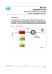
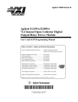
As shown in Figure 1-1, two 2-wire 4x16 matrixes (Group A & Group B)
are implemented on the E8481A module PC board which contains 128
2-wire nodes or crosspoints. Each crosspoint in the matrix uses two Form-A
non-latching relays to switch both High (H) and Low (L) signals. By closing
or opening the appropriate channel relays, the row is connected to or
disconnected from the column. Multiple switch relays can be closed at a
time, allowing any combination of rows connected to columns.
Since the relays are nonlatching, the channel relays are all open during
power-up, power-down, or following a reset.
Chapter 1
Getting Started
11
Group A
Column 00 - 15
Group B
Column 16 - 31
Row 0 3
Row 03
0300 0301 0302 0303 0304 0305 0306 0307 0308 0309 0310 0311 0312 0313 0314 0315
0316 0317 0318 0319 0320 0321 0322 0323 0324 0325 0326 0327 0328 0329 0330 0331
0200 0201 0202 0203 0204 0205 0206 0207 0208 0209 0210 0211 0212 0213 0214 0215
0216 0217 0218 0219 0220 0221 0222 0223 0224 0225 0226 0227 0228 0229 0230 0231
0100 0101 0102 0103 0104 0105 0106 0107 0108 0109 0110 0111 0112 0113 0114 0115
0116 0117 0118 0119 0120 0121 0122 0123 0124 0125 0126 0127 0128 0129 0130 0131
0000 0001 0002 0003 0004 0005 0006 0007 0008 0009 0010 0011 0012 0013 0014 0015
0016 0017 0018 0019 0020 0021 0022 0023 0024 0025 0026 0027 0028 0029 0030 0031
Row 0 2
Row 02
Row 0 1
Row 01
Row 00
Row 0 0
C00
C01 C02 C03 C04 C05 C06 C07 C08 C09 C10
0005
C11 C12 C13 C14 C15
C16
C17 C18 C19 C20 C21 C22 C23 C24 C25 C26
C27 C28 C29 C30 C31
CH0005
(Row 00, Column 05)
Figure 1-1. Agilent E8481A Simplified Schematic
Function Modes
When shipped from the factory, the E8481A is configured as a 4x32 2-wire
Matrix Switch module. All columns (00-31) are switched to rows (00-03) of
Group A with 50 MHz bandwidth. By disconnecting the rows of the Group
A and the Group B with SCPI command ([ROUTe:]FUNCtion), the module
can be reconfigured as two independent 4x16 matrixes. In such case,
columns 00-15 are switched to rows 00-03 of Group A, and columns 16-31
are switched to rows 00-03 of Group B with bandwidth up to 70 MHz.
For more information about the related SCPI commands, see
“[ROUTe:]FUNCtion” on page 72 of this manual. You can also change the
function mode by directly writing to the NVRAM Data Register of the
module, see “Setting Module Function Mode” on page 109 of this manual
for details.
NOTE
At power up/down or reset, the module will not change the function mode
set for it, unless another [ROUTe:]FUNCtion command is executed to
change the mode.
NOTE
DO NOT make connections on the rows 00-03 connectors of Group B when
in the 4x32 configuration. These connectors are used only when in the Dual
4x16 configuration.
Typical
Configuration
12
Getting Started
For a Standard Commands for Programmable Instruments (SCPI)
environment, one or more E8481A modules can be configured as a
switchbox instrument. For a switchbox instrument, all modules within the
instrument can be addressed using a single interface address.
Chapter 1
Instrument Definition
The plug-in modules installed in an Agilent mainframe or used with an
Agilent command module are treated as independent instruments, each
having a unique secondary GPIB address. Each instrument is also assigned
a dedicated error queue, input and output buffers, status registers and, if
applicable, dedicated mainframe/command module memory space for
readings or data. An instrument may be composed of a single plug-in
module (such as a counter) or multiple plug-in modules (for a switchbox or
scanning multimeter instrument).
Programming the Module
To program the module using SCPI commands, you must select the
controller language, interface address, and SCPI commands to be used. See
the C-Size VXIbus System Configuration Guide for detailed interface
addressing and controller language information. For uses in other systems or
mainframes, see the appropriate manuals. For more details of SCPI
commands applicable to the module, refer to Chapter 4 of this manual.
NOTE
This section only discusses SCPI programming. The module can also be
programmed by writing directly to its registers. See Appendix B for details
on register programming.
Specifying SCPI
Commands
To address specific channels within an E8481A module, you must specify
the appropriate SCPI command and matrix channel addresses. Table 1-1
lists the most commonly used commands. Refer to Chapter 4 of this manual
for a complete list of SCPI commands used for the matrix switch module.
Table 1-1. Commonly Used SCPI Commands
SCPI Commands
Channel Addresses
Commands Description
CLOSe <channel_list>
Closes the relay(s) specified.
OPEN <channel_list>
Opens the relay(s) specified.
SCAN <channel_list>
Closes a set of relays, one at a time.
Only valid channel addresses can be included in a channel_list. For the
E8481A, the channel address has the form of (@ssrrcc) where
ss = card number (01-99)
rr = row number of the matrix (00-03)
cc = column number of the matrix (00-31)
To specify a channel_list, use the form of:
• (@ssrrcc) for a single channel
• (@ssrrcc,ssrrcc,...) for multiple channels
Chapter 1
Getting Started
13
• (@ssrrcc:ssrrcc) for sequential channels
• (@ssrrcc:ssrrcc,ssrrcc:ssrrcc) for groups of sequential channels
• or any combination of the above.
NOTE
Only valid channels can be accessed in a channel list or channel range.
Channel numbers can be entered in the channel_list in any random order.
However, the channel range must be from a lower channel number to a
higher channel number. For example, CLOS (@10000:10312) is
acceptable, but CLOS (@10312:10000) generates an error.
Card Number
The card number (ss of the channel_list) identifies which module within a
switchbox will be addressed. The card number assigned depends on the
switch configuration used. Leading zeroes can be ignored for the card
number.
• Single-module Switchbox. In a single-module switchbox
configuration, the card number is always 01.
• Multiple-module Switchbox. In a multiple-module switchbox
configuration, modules are set to successive logical addresses. The
module with the lowest logical address is always card number 01. The
module with the next successive logical address is card number 02,
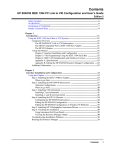
and so on. Figure 1-2 illustrates the card numbers and logical
addresses of a typical multiple-module switchbox installed in an
Agilent C-Size mainframe with an Agilent command module.
Multiple-Module Switchbox Card Numbers
Card Number 01
Command
Module
Matrix Switch Module
Logical Address = 112
Secondary Address = 14
Card Number 02
Matrix Switch Module
Logical Address = 113
Card Number 03
Matrix Switch Module
Logical Address = 114
Note: Physical placement of the module in the logical address
order is not required, but is recommended.
Figure 1-2. Card Numbers in a Multiple-modules Switchbox
14
Getting Started
Chapter 1
Channel Number
The channel number (rrcc of the channel_list) identifies which relay on the
selected module will be addressed. The channel numbers are:
row number: rr = 00 - 03 (two digits)
column number: cc = 00 - 31 (two digits)
For example, CLOS (@10214) will close channel relays on row 02,
column 14 of an E8481A module.
Initial Operation
Use the following example programs to perform the initial operation on the
E8481A module. To run the programs, an Agilent E1406A command
module is required. Also, you must download the E8481A SCPI driver into
the E1406A command module and have the Agilent SICL Library, the VISA
extensions, and an Agilent 82350 GPIB card installed and properly
configured in your PC.
In the examples, the computer interfaces to the mainframe via GPIB. The
GPIB interface select code is 7, the GPIB primary address is 09, and the
E8481A module is at logical address 112 (secondary address = 112/8 = 14).
Refer to the Agilent E1406A Command Module User’s Guide for more
addressing information. For more details on the related SCPI commands
used in the examples, see Chapter 4 of this manual.
Example: Closing a
Channel (HTBasic)
This example program was written in HTBasic programming language. The
program closes channel 0002, then queries its state. The result is returned to
the computer and displayed (“1” = channel closed, “0” = channel open).
10
20
30
40
DIM Ch_Stat$[20]
OUTPUT 70914; "*RST"
OUTPUT 70914; "CLOS (@10002)"
OUTPUT 70914; "CLOS? (@10002)"
50 ENTER 70914;Ch_Stat$
60 PRINT Ch_Stat$
! Dimension a variable.
! Resets the module.
! Close channel 10002.
! Query channel 10002 closed
state.
! Enter results into Ch_stat$.
! Display results, “1” should be
returned.
70 END
Example: Closing a
Channel (C/C++)
This example program was developed and tested in Microsoft® Visual C++
6.0 but should compile under any standard ANSI C compiler. The program
closes channel 0002, then queries its state. The result is returned to the
computer and displayed (“1” = channel closed, “0” = channel open).
#include <visa.h>
#include <stdio.h>
#include <stdlib.h>
/* Module logical address is 112, secondary address is 14 */
#define INSTR_ADDR "GPIB0::9::14::INSTR"
Chapter 1
Getting Started
15
int main()
{
ViStatus errStatus;
ViSession viRM;
ViSession E8481A;
char state[10];
/* Status from each VISA call */
/* Resource manager session */
/* Module session */
/* Channel state */
/* Open the default resource manager */
errStatus = viOpenDefaultRM (&viRM);
if(VI_SUCCESS > errStatus){
printf("ERROR: viOpenDefaultRM() returned 0x%x\n", errStatus);
return errStatus;}
/* Open the module instrument session */
errStatus = viOpen(viRM,INSTR_ADDR, VI_NULL,VI_NULL,&E8481A);
if(VI_SUCCESS > errStatus){
printf("ERROR: viOpen() returned 0x%x\n", errStatus);
return errStatus;}
/* Reset the module */
errStatus = viPrintf(E8481A, "*RST;*CLS\n");
if(VI_SUCCESS > errStatus){
printf("ERROR: viPrintf() returned 0x%x\n", errStatus);
return errStatus;}
/* Close channel 0002 */
errStatus = viPrintf(E8481A, "CLOS (@10002)\n");
if(VI_SUCCESS > errStatus){
printf("ERROR: viPrintf() returned 0x%x\n", errStatus);
return errStatus;}
/* Query state of channel 0002 */
errStatus = viQueryf(E8481A, "ROUT:CLOS? (@10002)\n", "%t",state);
if (VI_SUCCESS > errStatus) {
printf("ERROR: viQueryf() returned 0x%x\n", errStatus);
return errStatus;}
printf("Channel State is: %s\n",state);
/* Close the module instrument session */
errStatus = viClose (E8481A);
if (VI_SUCCESS > errStatus) {
printf("ERROR: viClose() returned 0x%x\n", errStatus);
return 0;}
/* Close the resource manager session */
errStatus = viClose (viRM);
if (VI_SUCCESS > errStatus) {
printf("ERROR: viClose() returned 0x%x\n", errStatus);
return 0;}
return VI_SUCCESS;
}
16
Getting Started
Chapter 1
Chapter 2
Configuring the Module
About This Chapter
This chapter shows how to configure the Matrix Switch module for use in a
VXIbus mainframe, install it in a mainframe, and connect external wiring to
the matrix module. Chapter contents include:
• Warnings and Cautions . . . . . . . . . . . . . . . . . . . . . . . . . . . . .
• Setting the Logical Address . . . . . . . . . . . . . . . . . . . . . . . . .
• Setting the Interrupt Priority . . . . . . . . . . . . . . . . . . . . . . . . .
• Installing the Matrix Switch Module in a Mainframe. . . . . .
• Connectors Pinouts . . . . . . . . . . . . . . . . . . . . . . . . . . . . . . . .
• Screw Type Terminal Module . . . . . . . . . . . . . . . . . . . . . . . .
• SMB Type Terminal Module . . . . . . . . . . . . . . . . . . . . . . . .
• Wiring a Terminal Module . . . . . . . . . . . . . . . . . . . . . . . . . .
• Attaching a Terminal Module to the Matrix . . . . . . . . . . . . .
17
18
19
20
21
22
23
24
26
Warnings and Cautions
WARNING
SHOCK HAZARD. Only qualified, service-trained personnel who
are aware of the hazards involved should install, configure, or
remove the Matrix switch module. Remove all power sources
from the mainframe and installed modules before installing or
removing a module.
Caution
MAXIMUM INPUTS. The maximum voltage that can be applied
to any terminal is 42 Vdc or 30 V ac rms. The maximum current
that can be applied to any terminal is 0.5 A dc or ac peak. The
maximum power that can be applied to any terminal is 5 W or
5 VA (resistive). Exceeding any limit may damage the Matrix
Switch module.
STATIC ELECTRICITY. Static electricity is a major cause of
component failure. To prevent damage to the electrical
components in the matrix module, observe anti-static
techniques whenever removing or installing a module or
whenever working on a module.
Chapter 2
Configuring the Module
17
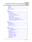
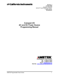
Setting the Logical Address
The logical address switch (LADDR) factory setting is 112. Valid address
values are from 1 to 255. Refer to Figure 2-1 for the address switch position
and setting information.
NOTE
The address switch selected value must be a multiple of 8 if the module is
the first module in a switchbox used with a VXIbus command module, and
being instructed by SCPI commands.
Logical Address
Switch Location
64 + 32 + 16 = 112
0
1
8
16
32
64
128
1
2
4
0 1 2 3 4 5 6 7
Logical Address = 112
Figure 2-1. Setting the Logical Address Switch
18
Configuring the Module
Chapter 2
Setting the Interrupt Priority
The E8481A module generates an interrupt after a channel has been closed.
These interrupts are sent to, and acknowledgments are received from, the
command module (Agilent E1406A) via the VXIbus backplane interrupt
lines.
For most applications the default interrupt priority line should not have to be
changed. This is because the VXIbus interrupt lines have the same priority
and interrupt priority is established by installing modules in slots
numerically closest to the command module. Thus, slot 1 has a higher
priority than slot 2, slot 2 has a higher priority than slot 3, etc.
By default, the interrupt priority level is Level 1. It can be set to any one of
the VXI backplane lines 1-7 (corresponding to Levels 1-7) either by sending
SCPI or directly writing to the Interrupt Selection Register. Level 1 is the
lowest priority and Level 7 is the highest priority. The interrupt can also be
disabled at power-up, after a SYSRESET, or by sending SCPI or directly
writing to the Status/Control Register. See Page 59 of this manual for more
details of the related SCPI commands. For more information about register
writing, see “Register-Based Programming” on page 97 of this manual.
NOTE
Chapter 2
Changing the interrupt priority level is not recommended. DO NOT change
it unless specially instructed to do so. Refer to the E1406A Command
Module User’s Manual for more details.
Configuring the Module
19
Installing the Matrix Switch Module in a Mainframe
The Agilent E8481A may be installed in any slot (except slot 0) in a C-size
VXIbus mainframe. Refer to Figure 2-2 to install the module in a
mainframe.
Figure 2-2. Installing the Matrix Switch Module in a VXIbus Mainframe
20
Configuring the Module
Chapter 2
Connecting User Inputs
The Agilent E8481A Matrix Switch module is not supplied with terminal
modules which must be ordered separately. Two types of terminal modules
are available for the Agilent E8481A Matrix Switch module. Order Option
106 if a screw type terminal module is desired. If an SMB terminal module
is desired, order Option 105. User inputs to the matrix switch module are
made via the Row and Column terminal connectors on these terminal
modules. The following sections provide the detailed information on the
module’s connectors pinout, the screw type terminal module and the SMB
terminal module, as well as on how to connect field wiring to the terminal
module.
Connectors Pinout
Figure 2-3 shows the front panel of the Agilent E8481A and the connectors
pinout which mates to the terminal module.
Group A
A
Pin 1
Pin 1
Pin 1
J1
Group A
ABC
Pin 1
Pin 1
ABC
Group B
J2
Pin32
B
ROWA_0H
Pin 1
C
ROWA_0L
Pin 1
NC
COL_0L
COL_0H
NC
COL_1L
COL_1H
NC
NC
NC
NC
COL_2L
COL_2H
NC
NC
NC
NC
COL_3L
COL_3H
NC
NC
NC
NC
COL_4L
COL_4H
NC
NC
NC
NC
COL_5L
COL_5H
NC
NC
NC
NC
COL_6L
COL_6H
NC
COL_7L
COL_7H
NC
ROWA_1H
ROWA_1L
NC
NC
NC
NC
ROWA_2H
ROWA_2L
NC
COL_8L
COL_8H
NC
COL_9L
COL_9H
NC
NC
NC
NC
COL_10L
COL_10H
NC
NC
NC
NC
COL_11L
COL_11H
NC
NC
NC
NC
COL_12L
COL_12L
NC
NC
NC
NC
COL_13L
COL_13H
NC
NC
NC
NC
COL_14L
COL_14H
NC
NC
NC
NC
COL_15L
COL_15H
NC
ROWA_3H
Pin32
ROWA_3L
Pin32
Group B
A
Pin 1
NC
Pin32
B
ROWB_0H
Pin 1
C
ROWB_0L
Pin 1
NC
COL_16L
COL_16H
NC
COL_17L
COL_17H
NC
NC
NC
NC
COL_18L
COL_18H
NC
NC
NC
NC
COL_19L
COL_19H
NC
NC
NC
NC
COL_20L
COL_20H
NC
NC
NC
NC
COL_21L
COL_21H
NC
NC
NC
NC
COL_22L
COL_22H
NC
COL_23L
COL_23H
NC
ROWB_1H
ROWB_1L
NC
NC
NC
NC
ROWB_2H
ROWB_2L
NC
COL_24L
COL_24H
NC
COL_25L
COL_25H
NC
NC
NC
NC
COL_26L
COL_26H
NC
NC
NC
NC
COL_27L
COL_27H
NC
NC
NC
NC
COL_28L
COL_28L
NC
NC
NC
NC
COL_29L
COL_29H
NC
NC
NC
NC
COL_30L
COL_30H
NC
NC
NC
NC
COL_31L
COL_31H
ROWB_3H
Pin32
ROWB_3L
NC
Pin32
NC
Figure 2-3. Agilent E8481A Matrix Switch Connectors Pinout
Chapter 2
Configuring the Module
21
Screw Type
Terminal Module
Figure 2-4 shows the Option 106 screw type terminal module connectors
and associated row/column designators.
Mating to the J1 and J2 connectors
on the front panel of the E8481A
J1
H
L
H
COL0
L
H
L
COL2 COL4
H
L
H
L
COL1 COL3
H L
ROWA0
H
J2
L
H
COL6
H
L
COL5
L
H
L
H
L
H
L
H
COL9 COL11 COL13 COL15
H
L
COL7
H L
ROWA1
H
L
H
L
H
L
H
L
H
H
COL8 COL10 COL12 COL14
H L
ROWA2
L
L
COL16 COL18
H L
ROWA3
L
H
L
H
L
H
COL20 COL22
H
L
H
L
L
H
L
H
COL17 COL19 COL21 COL23
H L
ROWB0
H
L
H
L
H
L
COL25 COL27 COL29 COL31
H L
ROWB1
L
H
L
H
L
H
L
COL24 COL26 COL28 COL30
H L
ROWB2
H L
ROWB3
Note: RowB 0-3 connectors are used only in Dual 4x16 configuration.
Figure 2-4. Screw Type Terminal Module
22
Configuring the Module
Chapter 2
SMB Type Terminal
Module
Figure 2-5 shows the Option 105 SMB type terminal module connectors
and associated row/column designators. This SMB terminal module
provides a convenient way to connect the field wiring to the matrix switch
module via SMB cables.
Mating to the J1 and J2 connectors
on the front panel of the E8481A
COL31
COL29
COL30
COL27
ROWB1 ROWB2
COL28
COL26
COL24
COL25
COL22
COL23
COL21
COL20
COL18
COL19
COL16
ROWB0
COL17
ROWA3
COL14
COL13
COL12
COL15
ROWA1 ROWA2
COL10
COL8
COL9
COL11
J2
COL6
COL7
COL4
COL5
COL2
ROWA0
COL3
COL1
COL0
J1
ROWB3
Note: RowB 0-3 connectors are used only in Dual 4x16 configuration.
Figure 2-5. SMB Terminal Module
Chapter 2
Configuring the Module
23
Wiring a Terminal
Module
The following illustrations show how to connect field wiring to the screw
type or SMB type terminal module, and how to attach the terminal module
to the relay matrix switch module.
Figure 2-6. Wiring a Terminal Module (continued on next page)
24
Configuring the Module
Chapter 2
6. Replace Clear Cover
7. Attach the Terminal Module to the Matrix
(see Figure 2-7 for more information)
Extraction
Levers
Use a small
screwdriver
to release the
two extraction
levels.
E8481A
Module
A. Hook in the top cover tabs onto the fixture.
B. Press down and tighten screws.
9. Push in the Extraction Levers to Lock the
Terminal Module onto the Matrix Module
Notes:
* Be sure the wires make good
connections on the terminal
modules.
* DO NOT make connections on
the RowB_0 through RowB_3
connectors when in 4x32 mode.
Extraction
Levers
* To remove the terminal module
from the E8481A, use a small
screwdriver to release the two
extraction levels and push both
evels out simultaneously
to free it from the E8481A
Matrix Module.
Figure 2-6. Wiring a Terminal Module
Chapter 2
Configuring the Module
25
Attaching a
Terminal Module to
the Matrix Module
1
Figure 2-7 shows how to attach a terminal module to the E8481A Relay
Matrix Switch module.
Extend the Extraction Levels on the
Terminal Module.
Extraction Lever
Use a small screwdriver
to release the two
extraction levers
E8481A
Module
Extraction Lever
2
Align the terminal module connectors
to the E8481A module connectors.
3
Apply gentle pressure to attach
the terminal module to the relay
matrix module.
4
Push the extraction levers
to lock the terminal module
onto the E8481A module.
Extraction Levers
To remove the terminal module from the E8481A,
use a small screwdriver to release the two extraction
levers and push both levers out simultaneously to
free it from the E8481A module.
Figure 2-7. Attach a Terminal Module to the E8481 Matrix Module
26
Configuring the Module
Chapter 2
Chapter 3
Using the Matrix Module
About This Chapter
This chapter uses typical examples to show how to use the E8481A Matrix
module. Chapter contents are:
• Power-On and Reset Conditions . . . . . . . . . . . . . . . . . . . . .
• Module Identification . . . . . . . . . . . . . . . . . . . . . . . . . . . . . .
• Setting Module Function Mode . . . . . . . . . . . . . . . . . . . . . .
• Switching Channels. . . . . . . . . . . . . . . . . . . . . . . . . . . . . . . .
• Using State Patterns to Switch Channels . . . . . . . . . . . . . . .
• Scanning Channels Using Trig In/Out Ports . . . . . . . . . . . . .
• Scanning Channels Using TTL Trigger . . . . . . . . . . . . . . . .
• Using the Scan Complete Bit . . . . . . . . . . . . . . . . . . . . . . . .
• Querying the Matrix Module . . . . . . . . . . . . . . . . . . . . . . . .
• Recalling and Saving States . . . . . . . . . . . . . . . . . . . . . . . . .
• Detecting Error Conditions . . . . . . . . . . . . . . . . . . . . . . . . . .
• Synchronizing the Instruments . . . . . . . . . . . . . . . . . . . . . . .
28
28
30
32
34
37
42
47
49
50
51
51
All example programs in this chapter were developed on an external PC
using HTBasic or Visual C/C++ as the programming language. They are
tested with the following system configuration:
• An E1406A command module and an E8481A Matrix module are
installed in the mainframe.
• The computer is connected to the E1406A command module via GPIB
interface. The GPIB select code is 7, the GPIB primary address is 09,
and the E8481A module is at logical address 112 (secondary address =
112/8 = 14).
• The E8481A SCPI driver had been downloaded into the E1406A
command module.
• The SICL Library, the VISA extensions, and an Agilent 82350 GPIB
card had been installed and properly configured in the computer.
Refer to the Agilent E1406A Command Module User’s Guide for more
addressing information. For more details on the related SCPI commands
used in this chapter, see Chapter 4 of this manual.
NOTE
Chapter 3
Do not do register writes if you are controlling the module by a high level
driver such as SCPI or VXIplug&play. This is because the driver will not
know the module state and an interrupt may occur causing the driver
and/or command module to fail.
Using the Matrix Module
27
Power-On and Reset Conditions
At power-on or following a reset (*RST command), all channels of the
module are open. The *RST command also invalidates the current scan list
(that is, you must specify a new scan list for scanning). Command
parameters are set to the default conditions as shown below.
Table 3-1. E8481A Default Conditions for Power-on and Reset
Parameter
Default
Description
ARM:COUNt
1
Number of scanning cycles is 1.
TRIGger:SOURce
IMM
Advances through a scanning list automatically.
INITiate:CONTinuous
OFF
Continuous scanning is disabled.
OUTPut:ECLTrgn[:STATe]
OFF
Trigger output from ECL trigger line is disabled.
OUTPut[:EXTernal][:STATe]
OFF
Trigger output from "Trig Out" port is disabled.
OUTPut:TTLTrgn[:STATe]
OFF
Trigger output from TTL trigger line is disabled.
Module Identification
The following example programs use the *RST, *CLS, *IDN?,
SYST:CTYP?, and SYST:CDES? commands to reset and identify the
Matrix module.
Example:
Identifying Module
(HTBasic)
10 DIM A$[50], B$[50], C$[50]
30 OUTPUT 70914; "*IDN?"
40 ENTER 70914; A$
! Dimension three string
variables to fifty characters.
! Reset the module and clear
status registers.
! Query module identification.
! Enter the result into A$.
50 OUTPUT 70914; "SYST:CDES? 1"
60 ENTER 70914; B$
! Query for module description.
! Enter the result into B$.
70 OUTPUT 70914; "SYST:CTYP? 1"
80 ENTER 70914; C$
! Query for module type.
! Enter the result into C$.
90 PRINT A$, B$, C$
! Print the contents of the
variable A$, B$ and C$.
20 OUTPUT 70914; "*RST; *CLS"
100 END
28
Using the Matrix Module
Chapter 3
Example:
Identifying Module
(C/C++)
#include <visa.h>
#include <stdio.h>
#include <stdlib.h>
/* Module logical address is 112, secondary address is 14 */
#define INSTR_ADDR "GPIB0::9::14::INSTR"
int main()
{
ViStatus errStatus;
ViSession viRM;
ViSession E8481A;
char id_string[256];
char m_desp[256];
char m_type[256];
/* Status from each VISA call */
/* Resource manager session */
/* Module session */
/* ID string */
/* Module description */
/* Module type */
/* Open the default resource manager */
errStatus = viOpenDefaultRM (&viRM);
if(VI_SUCCESS > errStatus){
printf("ERROR: viOpenDefaultRM() returned 0x%x\n", errStatus);
return errStatus;}
/* Open the module instrument session */
errStatus = viOpen(viRM,INSTR_ADDR, VI_NULL,VI_NULL,&E8481A);
if(VI_SUCCESS > errStatus){
printf("ERROR: viOpen() returned 0x%x\n", errStatus);
return errStatus;}
/* Reset the matrix module and clear the status registers */
errStatus = viPrintf(E8481A, "*RST;*CLS\n");
if(VI_SUCCESS > errStatus){
printf("ERROR: viPrintf() returned 0x%x\n", errStatus);
return errStatus;}
/* Query the module ID string */
errStatus = viQueryf(E8481A, "*IDN?\n", "%t", id_string);
if (VI_SUCCESS > errStatus) {
printf("ERROR: viQueryf() returned 0x%x\n", errStatus);
return errStatus;}
printf("ID is %s\n", id_string);
/* Query the module description */
errStatus = viQueryf(E8481A, "SYST:CDES? 1\n", "%t", m_desp);
if (VI_SUCCESS > errStatus) {
printf("ERROR: viQueryf() returned 0x%x\n", errStatus);
return errStatus;}
printf("Module Description is %s\n", m_desp);
Chapter 3
Using the Matrix Module
29
/* Query the module type */
errStatus = viQueryf(E8481A, "SYST:CTYP? 1\n", "%t", m_type);
if (VI_SUCCESS > errStatus) {
printf("ERROR: viQueryf() returned 0x%x\n", errStatus);
return errStatus;}
printf("Module Type is %s\n", m_type);
/* Close the module instrument session */
errStatus = viClose (E8481A);
if (VI_SUCCESS > errStatus) {
printf("ERROR: viClose() returned 0x%x\n", errStatus);
return 0;}
/* Close the resource manager session */
errStatus = viClose (viRM);
if (VI_SUCCESS > errStatus) {
printf("ERROR: viClose() returned 0x%x\n", errStatus);
return 0;}
return VI_SUCCESS;
}
Setting Module Function Mode
When shipped from the factory, the E8481A is configured as a 4x32 matrix
module. The E8481A matrix module can also be set to function as two
independent 4x16 matrixes. Use the FUNC <card_num>, <mode> command
to set the module to the desired function mode.
The following example programs were written in HTBasic and Visual
C/C++ programming languages. They will set the E8481A to function as
two independent 4x16 matrixes, then query the setting. The result is returned
to the computer and displayed ("SINGLE4X32" indicates the module
functioned as a 4x32 Matrix, "DUAL4X16" indicates the module functioned
as two independent 4x16 matrixes).
Example: Setting
Function Mode
(HTBasic)
10 DIM Func$[20]
20 OUTPUT 70914; "*RST; *CLS"
! Dimension a string variable
to twenty characters.
! Reset the module and clear
status registers.
30 OUTPUT 70914; "ROUT:FUNC 1, DUAL4X16"
! Set the module as dual 4x16
matrixes.
40 OUTPUT 70914; "ROUT:FUNC? 1"
50 ENTER 70914; Func$
60 PRINT A$
! Query the function mode.
! Enter the result into Func$.
! "DUAL4X16" will be
displayed.
70 END
30
Using the Matrix Module
Chapter 3
Example: Setting
Function Mode
(C/C++)
#include <visa.h>
#include <stdio.h>
#include <stdlib.h>
/* Module logical address is 112, secondary address is 14 */
#define INSTR_ADDR "GPIB0::9::14::INSTR"
int main()
{
ViStatus errStatus;
ViSession viRM;
ViSession E8481A;
char func[20];
/* Status from each VISA call */
/* Resource manager session */
/* Module session */
/* Function mode */
/* Open the default resource manager */
errStatus = viOpenDefaultRM (&viRM);
if(VI_SUCCESS > errStatus){
printf("ERROR: viOpenDefaultRM() returned 0x%x\n", errStatus);
return errStatus;}
/* Open the module instrument session */
errStatus = viOpen(viRM,INSTR_ADDR, VI_NULL,VI_NULL,&E8481A);
if(VI_SUCCESS > errStatus){
printf("ERROR: viOpen() returned 0x%x\n", errStatus);
return errStatus;}
/* Reset the module */
errStatus = viPrintf(E8481A, "*RST;*CLS\n");
if(VI_SUCCESS > errStatus){
printf("ERROR: viPrintf() returned 0x%x\n", errStatus);
return errStatus;}
/* Set module to function as dual 4x16 matrixes */
errStatus = viPrintf(E8481A, "ROUT:FUNC 1, DUAL4X16\n");
if(VI_SUCCESS > errStatus){
printf("ERROR: viPrintf() returned 0x%x\n", errStatus);
return errStatus;}
/* Query the function mode set for the module */
errStatus = viQueryf(E8481A, "ROUT:FUNC? 1\n", "%t", func);
if (VI_SUCCESS > errStatus) {
printf("ERROR: viQueryf() returned 0x%x\n", errStatus);
return errStatus;}
printf("The module is set to function as: %s\n", func);
/* Close the module instrument session */
errStatus = viClose (E8481A);
if (VI_SUCCESS > errStatus) {
printf("ERROR: viClose() returned 0x%x\n", errStatus);
return 0;}
Chapter 3
Using the Matrix Module
31
/* Close the resource manager session */
errStatus = viClose (viRM);
if (VI_SUCCESS > errStatus) {
printf("ERROR: viClose() returned 0x%x\n", errStatus);
return 0;}
return VI_SUCCESS;
}
Switching Channels
Use CLOSe <channel_list> to close one or more matrix channels, and use
OPEN <channel_list> to open the channel(s). The channel_list has the form:
• (@ssrrcc) for a single channel
• (@ssrrcc,ssrrcc) for multiple channels
• (@ssrrcc:ssrrcc) for sequential channels
• (@ssrrcc:ssrrcc,ssrrcc:ssrrcc) for groups of sequential channels
• or any combination of the above.
where ss = card number (01-99), rr = row number (00-03) and
cc = column number (00-31).
The following example programs were written in HTBasic and Visual
C/C++ programming languages. They will show how to close/open
channels, then query their state. The result is returned to the computer and
displayed (1 = channel closed, 0 = channel open).
Example: Closing
Multiple Channels
(HTBasic)
10 DIM A$[20]
20 OUTPUT 70914; "*RST; *CLS"
! Dimension a string variable to
twenty characters.
! Reset the module and clear
status registers.
30 OUTPUT 70914; "ROUT:CLOS (@10003, 10102)"
! Close channels 10003
and 10102.
40 OUTPUT 70914; "ROUT:OPEN (@10003)"
! Open channel 10003.
50 OUTPUT 70914; "ROUT:CLOS? (@10003, 10102)"
! Query closure state of channels
10003 and 10102.
60 ENTER 70914; A$
70 PRINT A$
80 END
32
Using the Matrix Module
! Enter the result into A$.
! "0,1" will be displayed.
Chapter 3
Example: Closing
Multiple Channels
(C/C++)
#include <visa.h>
#include <stdio.h>
#include <stdlib.h>
/* Module logical address is 112, secondary address is 14 */
#define INSTR_ADDR "GPIB0::9::14::INSTR"
int main()
{
ViStatus errStatus;
ViSession viRM;
ViSession E8481A;
char ch_stat[10];
/* Status from each VISA call */
/* Resource manager session */
/* Module session */
/* Channel state */
/* Open the default resource manager */
errStatus = viOpenDefaultRM (&viRM);
if(VI_SUCCESS > errStatus){
printf("ERROR: viOpenDefaultRM() returned 0x%x\n", errStatus);
return errStatus;}
/* Open the module instrument session */
errStatus = viOpen(viRM,INSTR_ADDR, VI_NULL,VI_NULL,&E8481A);
if(VI_SUCCESS > errStatus){
printf("ERROR: viOpen() returned 0x%x\n", errStatus);
return errStatus;}
/* Reset the module */
errStatus = viPrintf(E8481A, "*RST;*CLS\n");
if(VI_SUCCESS > errStatus){
printf("ERROR: viPrintf() returned 0x%x\n", errStatus);
return errStatus;}
/* Query closure state of channel 0002 after a reset */
errStatus = viQueryf(E8481A,"ROUT:CLOS? (@10002)\n","%t",ch_stat);
if (VI_SUCCESS > errStatus) {
printf("ERROR: viQueryf() returned 0x%x\n", errStatus);
return errStatus;}
printf("After reset, chan 10002 state is: %s\n", ch_stat);
/* Close channel 0002 of card 1*/
errStatus = viPrintf(E8481A, "CLOS (@10002)\n");
if(VI_SUCCESS > errStatus){
printf("ERROR: viPrintf() returned 0x%x\n", errStatus);
return errStatus;}
/* Query closure state of channel 0002 */
errStatus = viQueryf(E8481A,"ROUT:CLOS? (@10002)\n","%t",ch_stat);
if (VI_SUCCESS > errStatus) {
printf("ERROR: viQueryf() returned 0x%x\n", errStatus);
return errStatus;}
printf("Now, channel 10002 state is: %s\n", ch_stat);
Chapter 3
Using the Matrix Module
33
/* Close the module instrument session */
errStatus = viClose (E8481A);
if (VI_SUCCESS > errStatus) {
printf("ERROR: viClose() returned 0x%x\n", errStatus);
return 0;}
/* Close the resource manager session */
errStatus = viClose (viRM);
if (VI_SUCCESS > errStatus) {
printf("ERROR: viClose() returned 0x%x\n", errStatus);
return 0;}
return VI_SUCCESS;
}
Using State Patterns to Switch Channels
To improve the switching throughput, an 8 kB non-volatile RAM
(NVRAM) is provided on the module, allowing to store up to 511 state
patterns for all 128 channels. Then you can operate the channel relays with
the stored pattern whenever you required. In this way, switching all 128
channels is almost as fast as switching a single channel.
The following example programs were written in HTBasic and Visual
C/C++ languages, respectively. Each uses a state pattern to operate the
channel relays. They first reset the module to open all channels of the
module, then set channels state in a pattern (including select a pattern
number, open all channels in the pattern, then close some of the channels in
the pattern). After having finished the pattern setting, you can use the saved
pattern to operate the channels whenever you require.
For the related SCPI commands used in these examples, see
[ROUTe:]PATTern: subsystem on Page 74 of this manual. If you want to
learn more about the pattern structure in the NVRAM, see “NVRAM
Control Registers” on page 107 of this manual.
NOTE
Example: Using a
State Pattern to
Switch Channels
(HTBasic)
Before setting/querying channels open/closed state in a pattern, you must
use PATT:NUMB command to select a pattern first.
10 DIM Ch_PatStat$[50],Ch_Stat$[50],Err_num$[256]
! Dimension three string
variables.
20 OUTPUT 70914; "*RST;*CLS"
! Reset the module and clear
Status registers.
30 OUTPUT 70914; "PATT:NUMB 1,10"
! Select pattern 10 of module #1.
40 OUTPUT 70914; "PATT:OPEN (@10000:10331)"
! Set all 128 channels in pattern
10 to the open state.
34
Using the Matrix Module
Chapter 3
50 OUTPUT 70914; "PATT:CLOS (@10000,10101,10202)"
! Set channels 10000, 10101 and
10202 to the closure state in
pattern 10.
60 OUTPUT 70914; "PATT:CLOS? (@10000,10101,10202)"
! Query to verify the settings in
pattern 10.
70 ENTER 70914; Ch_PatStat$
! Enter the result into the
variable.
80 PRINT "The channel states in Pattern 10: ";Ch_PatStat$
! "1,1,1" should be displayed.
90 OUTPUT 70914; "ROUT:CLOS? (@10000,10101,10202)"
! Query to verify the actual state
of these channels.
100 ENTER 70914; Ch_Stat$
! Enter the result into Ch_Stat$.
110 PRINT "Channel States: ";Ch_Stat$
! "0,0,0" should be displayed.
120 OUTPUT 70914; "PATT:ACT 1,10"
! Recall pattern 10 to operate all
channels of module #1.
130 OUTPUT 70914; "ROUT:CLOS? (@10000,10101,10202)"
! Query to verify the closure
state of these channels.
140 ENTER 70914; Ch_Stat$
! Enter the result into the
variable.
150 PRINT "Channel States: ";Ch_Stat$
! "1,1,1" should be displayed.
160
170
180
190
Example: Using a
State Pattern to
Switch Channels
(C/C++)
OUTPUT 70914; "SYST:ERR?"
ENTER 70914;Err_num$
PRINT "Error: ";Err_num$
END
! Check for a system error.
! Enter the error into Err_num$.
! Print error if any.
#include <visa.h>
#include <stdio.h>
#include <stdlib.h>
/* Module logical address is 112, secondary address is 14 */
#define INSTR_ADDR "GPIB0::9::14::INSTR"
int main()
{
ViStatus errStatus;
ViSession viRM;
ViSession E8481A;
char pstat[256];
char cstat[256];
/* Status from each VISA call */
/* Resource manager session */
/* Module session */
/* Channel state in pattern */
/* Channel state */
/* Open the default resource manager */
errStatus = viOpenDefaultRM (&viRM);
if(VI_SUCCESS > errStatus){
printf("ERROR: viOpenDefaultRM() returned 0x%x\n", errStatus);
return errStatus;}
Chapter 3
Using the Matrix Module
35
/* Open the module instrument session */
errStatus = viOpen(viRM,INSTR_ADDR, VI_NULL,VI_NULL,&E8481A);
if(VI_SUCCESS > errStatus){
printf("ERROR: viOpen() returned 0x%x\n", errStatus);
return errStatus;}
/* Reset the module */
errStatus = viPrintf(E8481A, "*RST;*CLS\n");
if(VI_SUCCESS > errStatus){
printf("ERROR: viPrintf() returned 0x%x\n", errStatus);
return errStatus;}
/* Select pattern 10 on module #1 for storing states*/
errStatus = viPrintf(E8481A, "PATT:NUMB 1, 10\n");
if(VI_SUCCESS > errStatus){
printf("ERROR: viPrintf() returned 0x%x\n", errStatus);
return errStatus;}
/* Open all channels in pattern 10 */
errStatus = viPrintf(E8481A, "PATT:OPEN (@10000:10331)\n");
if(VI_SUCCESS > errStatus){
printf("ERROR: viPrintf() returned 0x%x\n", errStatus);
return errStatus;}
/* Close channels 0000, 0101 and 0202 in pattern 10 */
errStatus = viPrintf(E8481A, "PATT:CLOS (@10000,10101,10202)\n");
if(VI_SUCCESS > errStatus){
printf("ERROR: viPrintf() returned 0x%x\n", errStatus);
return errStatus;}
/* Query channels 0000, 0101 and 0202 state in pattern 10 */
errStatus = viQueryf(E8481A, "PATT:CLOS?
(@10000,10101,10202)\n", "%t", pstat);
if(VI_SUCCESS > errStatus){
printf("ERROR: viPrintf() returned 0x%x\n", errStatus);
return errStatus;}
/* Query the actual states of channels 0000,0101and 0202 */
/* "0,0,0" should be displayed. */
errStatus = viQueryf(E8481A, "ROUT:CLOS?
(@10000,10101,10202)\n", "%t", cstat);
if (VI_SUCCESS > errStatus) {
printf("ERROR: viQueryf() returned 0x%x\n", errStatus);
return errStatus;}
printf("Before recall pattern, channel state is: %s\n", cstat);
/* Recall pattern 10 to operate relays on module #1*/
errStatus = viPrintf(E8481A, "PATT:ACT 1, 10\n");
if(VI_SUCCESS > errStatus){
printf("ERROR: viPrintf() returned 0x%x\n", errStatus);
return errStatus;}
36
Using the Matrix Module
Chapter 3
/* Verify whether channels 0000,0101,0202 are really closed */
/* "1,1,1" should be displayed after recalling the pattern. */
errStatus = viQueryf(E8481A, "ROUT:CLOS?
(@10000,10101,10202)\n", "%t", cstat);
if (VI_SUCCESS > errStatus) {
printf("ERROR: viQueryf() returned 0x%x\n", errStatus);
return errStatus;}
printf("After recall pattern, channel state is: %s\n", cstat);
/* Close the module instrument session */
errStatus = viClose (E8481A);
if (VI_SUCCESS > errStatus) {
printf("ERROR: viClose() returned 0x%x\n", errStatus);
return 0;}
/* Close the resource manager session */
errStatus = viClose (viRM);
if (VI_SUCCESS > errStatus) {
printf("ERROR: viClose() returned 0x%x\n", errStatus);
return 0;}
return VI_SUCCESS;
}
Scanning Channels
For the E8481A Matrix Switch module, scanning channels consists of
closing a set of channels, one at a time. You can scan any combination of
channels for a single-module or a multiple-module switchbox. Single,
multiple, or continuous scanning modes are available.
Use TRIGger:SOURce command to specify the source to advance the scan.
Use OUTPut subsystem commands to select the E1406A command module
Trig Out port, or ECL Trigger bus lines (0-1), or TTL Trigger bus lines
(0-7). Use ARM:COUNt <number> to set multiple/continuous scans (from 1
to 32,767 scans). Use INITiate:CONTinuous ON to set continuous scanning.
See Chapter 4 of this manual for information about these SCPI commands.
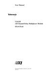
Example: Scanning
Channels Using
Trig In/Out Ports
This example uses E1406A command module’s "Trig In" and "Trig Out"
ports to synchronize the matrix module channel closures with an external
measurement multimeter (Agilent 34401A). See Figure 3-1 for typical user
connections. For measurement synchronization:
-- E1406A’s Trig Out port (connected to the 34401A multimeter’s
External Trigger port) is used by the matrix module to trigger the
multimeter to perform a measurement.
-- E1406A’s Trig In port (connected to the 34401A multimeter’s
Voltmeter Complete port) is used by the multimeter to advance the
matrix scan.
Chapter 3
Using the Matrix Module
37
For this example, Row 00 (High and Low) of the E8481A matrix module is
connected to the multimeter’s High and Low. The columns 00 through 15
are then scanned and different Device Under Test (DUTs) are switched in
for a measurement.
E1406A
Command Module
Trig In
Trig Out
VM Comp
Ext Trig
E8481A
Matrix Module
RowA 00L
RowA 00H
Agilent 34401A Multimeter (from rear view)
E8481A Opt 106
Terminal Module
Figure 3-1. Scanning Channels using Trig In/out Ports
Programming with
HTBasic
The following HTBasic program sets up the external multimeter (Agilent
34401A) to scan making DC voltage measurements. The Matrix module has
a logical address 112 (secondary address 14), and the external multimeter
has an address of 722.
10 DIM Rdgs(1:16)
20 OUTPUT 722; "*RST;*CLS"
30 OUTPUT 70914; "*RST;*CLS"
40 OUTPUT 722; "CONF:VOLT:DC 12"
50 OUTPUT 722; "TRIG:SOUR EXT"
60 OUTPUT 722; "TRIG:COUN 16"
70 OUTPUT 722; "INIT"
80 WAIT 1
90 OUTPUT 70914; "OUTP ON"
100 OUTPUT 70914; "TRIG:SOUR EXT"
38
Using the Matrix Module
! Dimension a variable to store
readings.
! Reset the dmm and clear its
status registers.
! Reset the matrix module and
clear its status registers.
! Set the dmm for DCV
measurement, 12 V maximum.
! Set the dmm trigger source to
EXTernal triggering.
! Set the dmm trigger count to16.
! Set the dmm to the
wait-for-trigger state.
! Wait for 1 second.
! Set the matrix output pulses on
E1406A "Trig Out" port when
channel closed.
! Set the matrix trigger source to
external triggering.
Chapter 3
110 OUTPUT 70914; "SCAN (@10000:10015)"
! Define channel list (row 00,
columns 00-15) for scanning.
120 OUTPUT 70914; "INIT"
! Start scan and close channel
10000.
130 OUTPUT 722; "FETCH?"
! Read measurement results
from the dmm.
140 ENTER 722; Rdgs(*)
! Enter measurement results.
150 PRINT Rdgs(*)
! Display measurement results.
160 END
Programming with C/C++
The following program was written and tested in Microsoft® Visual C++
using the VISA extensions but should compile under any standard ANSI C
compiler. This example configures the external multimeter (Agilent
34401A) to scan making DC voltage measurements.
#include <visa.h>
#include <stdio.h>
#include <stdlib.h>
/* Interface logical address is 112, Matrix secondary address is 14 */
#define INSTR_ADDR "GPIB0::9::14::INSTR"
/* interface address for 34401A Multimeter */
#define MULTI_ADDR "GPIB0::22::INSTR"
int main()
{
ViStatus errStatus;
ViSession viRM;
ViSession E8481A;
ViSession dmm;
int loop;
int opc_int;
double readings [16];
/* Status from each VISA call */
/* Resource manager session */
/* Module session */
/* Multimeter session */
/* loop counter */
/* OPC? variable */
/* Reading storage */
/* Open the default resource manager */
errStatus = viOpenDefaultRM (&viRM);
if(VI_SUCCESS > errStatus){
printf("ERROR: viOpenDefaultRM() returned 0x%x\n", errStatus);
return errStatus;}
/* Open the matrix module instrument session */
errStatus = viOpen(viRM,INSTR_ADDR, VI_NULL,VI_NULL,&E8481A);
if(VI_SUCCESS > errStatus){
printf("ERROR: viOpen() returned 0x%x\n", errStatus);
return errStatus;}
/* Open the multimeter instrument session */
errStatus = viOpen(viRM,MULTI_ADDR, VI_NULL,VI_NULL,&dmm);
if(VI_SUCCESS > errStatus){
printf("ERROR: viOpen() returned 0x%x\n", errStatus);
return errStatus;}
Chapter 3
Using the Matrix Module
39
/* Set timeout value for multimeter and matrix module */
viSetAttribute (dmm,VI_ATTR_TMO_VALUE,1000000);
viSetAttribute (E8481A,VI_ATTR_TMO_VALUE,1000000);
/* Reset the multimeter and clear its status registers */
errStatus = viPrintf(dmm, "*RST;*CLS\n");
if(VI_SUCCESS > errStatus){
printf("ERROR: viPrintf() returned 0x%x\n", errStatus);
return errStatus;}
/* Configure dmm for DCV measurements, 12V maximum */
errStatus = viPrintf(dmm, "CONF:VOLT:DC 12\n");
if(VI_SUCCESS > errStatus){
printf("ERROR: viPrintf() returned 0x%x\n", errStatus);
return errStatus;}
/* Set multimeter trigger source to EXTernal */
errStatus = viPrintf(dmm, "TRIG:SOUR EXT\n");
if(VI_SUCCESS > errStatus){
printf("ERROR: viPrintf() returned 0x%x\n", errStatus);
return errStatus;}
/* Set multimeter trigger count to 16 */
errStatus = viPrintf(dmm, "TRIG:COUN 16\n");
if(VI_SUCCESS > errStatus){
printf("ERROR: viPrintf() returned 0x%x\n", errStatus);
return errStatus;}
/* Initialize multimeter, wait for triggering */
errStatus = viPrintf(dmm, "INIT\n");
if(VI_SUCCESS > errStatus){
printf("ERROR: viPrintf() returned 0x%x\n", errStatus);
return errStatus;}
/* Wait for 1 second */
_sleep(1000);
/* Reset matrix module and clear its status registers */
errStatus = viPrintf(E8481A, "*RST;*CLS\n");
if (VI_SUCCESS > errStatus) {
printf("ERROR: viPrintf() returned 0x%x\n", errStatus);
return errStatus;}
/* Enable matrix module output pulses on E1406A "Trig Out" port */
/* when a channel is closed */
errStatus = viPrintf(E8481A, "OUTP ON\n");
if(VI_SUCCESS > errStatus){
printf("ERROR: viPrintf() returned 0x%x\n", errStatus);
return errStatus;}
40
Using the Matrix Module
Chapter 3
/* Set matrix trigger source to EXTernal */
errStatus = viPrintf(E8481A, "TRIG:SOUR EXT\n");
if(VI_SUCCESS > errStatus){
printf("ERROR: viPrintf() returned 0x%x\n", errStatus);
return errStatus;}
/* Set up a scan list */
errStatus = viPrintf(E8481A, "SCAN (@10000:10015)\n");
if(VI_SUCCESS > errStatus){
printf("ERROR: viPrintf() returned 0x%x\n", errStatus);
return errStatus;}
/* Pause until ready */
errStatus = viQueryf(E8481A, "*OPC?\n", "%t", opc_int);
if(VI_SUCCESS > errStatus){
printf("ERROR: viQueryf() returned 0x%x\n", errStatus);
return errStatus;}
/* Start scan and close channel 10000 */
errStatus = viPrintf(E8481A, "INIT\n");
if(VI_SUCCESS > errStatus){
printf("ERROR: viPrintf() returned 0x%x\n", errStatus);
return errStatus;}
/* Wait for scan to complete */
errStatus = viPrintf(E8481A, "STAT:OPER:ENAB 256\n");
if(VI_SUCCESS > errStatus){
printf("ERROR: viPrintf() returned 0x%x\n", errStatus);
return errStatus;}
for (; ;){
errStatus = viQueryf(E8481A, "*STB?\n", "%d", &opc_int);
if (opc_int&0x80)
break;}
printf("Scan has completed!");
/* Get readings from the multimeter */
errStatus = viQueryf(dmm, "FETC?\n", "%,16lf", readings);
if(VI_SUCCESS > errStatus){
printf("ERROR: viQueryf() returned 0x%x\n", errStatus);
return errStatus;}
/* Display the measurement results */
for (loop=0;loop<16;loop++) {
printf ("Reading %d is: %lf\n", loop, readings[loop]); }
/* Close the E8481A instrument session */
errStatus = viClose (E8481A);
if (VI_SUCCESS > errStatus) {
printf("ERROR: viClose() returned 0x%x\n", errStatus);
return 0;}
Chapter 3
Using the Matrix Module
41
/* Close the multimeter instrument session */
errStatus = viClose (dmm);
if (VI_SUCCESS > errStatus) {
printf("ERROR: viClose() returned 0x%x\n", errStatus);
return 0;}
/* Close the resource manager session */
errStatus = viClose (viRM);
if (VI_SUCCESS > errStatus) {
printf("ERROR: viClose() returned 0x%x\n", errStatus);
return 0;}
return VI_SUCCESS;
}
Example: Scanning
Channels Using
TTL Trigger
This example uses E1406A command module’s TTL Trigger Bus Lines to
synchronize matrix channel closures with a system multimeter (Agilent
E1412A). See Figure 3-2 for typical user connections. For measurement
synchronization:
-- E1406A’s TTL Trigger Bus Line 0 is used by the matrix module to
trigger the multimeter to perform a measurement.
-- E1406A’s TTL trigger bus line 1 is used by the multimeter to
advance the matrix scan.
Part of VXIbus
E1406A
Command Module
E8481A
Matrix Module
E1412A
Multimeter Module
E8481A Opt 105
Terminal Module
TTLTrg 0
TTLTrg 1
TTLTrg 0
RowA 0H
TTLTrg 1
RowA 0L
HI
LO
Figure 3-2. Scanning Using TTL Trigger Bus Lines
42
Using the Matrix Module
Chapter 3
Figure 3-2 shows how to connect the matrix module to the E1412A
multimeter module. The connections shown with dotted lines are not actual
hardware connections. These connections indicate how the E1406A
firmware operates to accomplish the triggering. For this example, Row 00
(High and Low) of the E8481A matrix module is connected to the
multimeter’s High and Low. The columns are then scanned and different
DUTS are switched in for a measurement.
Programming with
HTBasic
This example program was written in HTBasic programming language. It
configures the multimeter (E1412A) for DC voltage measurements, sets the
matrix module to scan channels on row 00, columns 00 through 15. The
E1412A multimeter has a GPIB address of 70903 and the matrix module has
a logical address of 112 (GPIB address of 70914).
10 DIM Rdgs(1:16)
20
30
40
50
60
70
80
! Dimension a variable to
store readings.
OUTPUT 70903; "*RST;*CLS"
! Reset the dmm and clear its
status registers.
OUTPUT 70914; "*RST;*CLS"
! Reset the matrix module and
clear its status registers.
OUTPUT 70903; "CONF:VOLT 12,MIN" ! Set the dmm for DCV
measurement, 12 V max, min
resolution.
OUTPUT 70903; "OUTP:TTLT1:STAT ON"
! Set the dmm pulses TTL trigger
line 1 on measurement
complete.
OUTPUT 70903; "TRIG:SOUR TTLT0" ! Set the dmm to be triggered by
TTL trigger line 0.
OUTPUT 70903; "TRIG:DEL 0.01"
! Set the dmm trigger delay time
to 10 ms
OUTPUT 70903; "TRIG:COUN 16"
! Set the dmm trigger count to16.
90 OUTPUT 70903; "*OPC?"
100 ENTER 70903; Check
110 OUTPUT 70903; "INIT"
! Check to see if dmm ready
! Set the dmm to the
wait-for-trigger state.
120 OUTPUT 70914; "OUTP:TTLT0:STAT ON"
! Set the matrix pulses TTL
trigger line 0 on channel
closed.
130 OUTPUT 70914; "TRIG:SOUR TTLT1" ! Set the matrix to be triggered
by TTL Trigger line 1.
140 OUTPUT 70914; "SCAN (@10000:10015)"
! Define channel list (row 00,
columns 00-15) to be scanned.
150 OUTPUT 70914; "INIT"
! Initialize scan and close
channel 10000.
160 OUTPUT 70903; "FETCH?"
170 ENTER 70903; Rdgs(*)
180 PRINT Rdgs(*)
190 END
Chapter 3
! Read measurement results
from the dmm.
! Enter measurement results.
! Display measurement results.
Using the Matrix Module
43
Programming with C/C++
The following program was written and tested in Microsoft® Visual C++
using the VISA extensions but should compile under any standard ANSI C
compiler. This example configures the multimeter for DC voltage
measurements, sets the matrix module to scan channels on row 00, columns
00 through 15.
#include <visa.h>
#include <stdio.h>
#include <stdlib.h>
/* Interface logical address is 112, module secondary address is 14 */
#define INSTR_ADDR "GPIB0::9::14::INSTR"
/* Interface address for E1412 Multimeter */
#define MULTI_ADDR "GPIB0::9::3::INSTR"
int main()
{
ViStatus errStatus;
ViSession viRM;
ViSession E8481A;
ViSession E1412A;
int loop;
char opc_int[21];
double readings [16];
/* Status from each VISA call */
/* Resource manager session */
/* Module session */
/* Multimeter session */
/* loop counter */
/* OPC? variable */
/* Reading storage */
/* Open the default resource manager */
errStatus = viOpenDefaultRM (&viRM);
if(VI_SUCCESS > errStatus){
printf("ERROR: viOpenDefaultRM() returned 0x%x\n", errStatus);
return errStatus;}
/* Open the matrix module instrument session */
errStatus = viOpen(viRM,INSTR_ADDR, VI_NULL,VI_NULL,&E8481A);
if(VI_SUCCESS > errStatus){
printf("ERROR: viOpen() returned 0x%x\n", errStatus);
return errStatus;}
/* Open the multimeter instrument session */
errStatus = viOpen(viRM,MULTI_ADDR, VI_NULL,VI_NULL,&E1412A);
if(VI_SUCCESS > errStatus){
printf("ERROR: viOpen() returned 0x%x\n", errStatus);
return errStatus;}
/* Set timeout value for multimeter and matrix module */
viSetAttribute (E1412A,VI_ATTR_TMO_VALUE,1000000);
viSetAttribute (E8481A,VI_ATTR_TMO_VALUE,1000000);
/* Reset the multimeter, clear status system */
errStatus = viPrintf(E1412A, "*RST;*CLS\n");
if(VI_SUCCESS > errStatus){
printf("ERROR: viPrintf() returned 0x%x\n", errStatus);
return errStatus;}
44
Using the Matrix Module
Chapter 3
/* Configure multimeter for DCV measurements, 12 V max, min resolution */
errStatus = viPrintf(E1412A, "CONF:VOLT 12,MIN\n");
if(VI_SUCCESS > errStatus){
printf("ERROR: viPrintf() returned 0x%x\n", errStatus);
return errStatus;}
/* Set multimeter to be triggered by TTL Trigger Line 0 */
errStatus = viPrintf(E1412A, "TRIG:SOUR TTLT0\n");
if(VI_SUCCESS > errStatus){
printf("ERROR: viPrintf() returned 0x%x\n", errStatus);
return errStatus;}
/* Enable the dmm pulses TTL trigger line 1 on measurement complete */
errStatus = viPrintf(E1412A, "OUTP:TTLT1 ON\n");
if(VI_SUCCESS > errStatus){
printf("ERROR: viPrintf() returned 0x%x\n", errStatus);
return errStatus;}
/* Set trigger delay time to 1 ms, trigger count to 16 */
errStatus = viPrintf(E1412A, "TRIG:DEL 0.001;COUN 16\n");
if(VI_SUCCESS > errStatus){
printf("ERROR: viPrintf() returned 0x%x\n", errStatus);
return errStatus;}
/* Pause until multimeter is ready */
errStatus = viQueryf(E1412A, "*OPC?\n", "%t", opc_int);
if(VI_SUCCESS > errStatus){
printf("ERROR: viQueryf() returned 0x%x\n", errStatus);
return errStatus;}
/* Initialize multimeter, wait for trigger */
errStatus = viPrintf(E1412A, "INIT\n");
if(VI_SUCCESS > errStatus){
printf("ERROR: viPrintf() returned 0x%x\n", errStatus);
return errStatus;}
/* Reset the matrix module, clear the status registers */
errStatus = viPrintf(E8481A, "*RST;*CLS\n");
if (VI_SUCCESS > errStatus) {
printf("ERROR: viPrintf() returned 0x%x\n", errStatus);
return errStatus;}
/* Set the matrix pulses TTL Trigger line 0 on channel closed */
errStatus = viPrintf(E8481A, "OUTP:TTLT0 ON\n");
if(VI_SUCCESS > errStatus){
printf("ERROR: viPrintf() returned 0x%x\n", errStatus);
return errStatus;}
/* Set the matrix to be triggered by TTL Trigger line 1 */
errStatus = viPrintf(E8481A, "TRIG:SOUR TTLT1\n");
if(VI_SUCCESS > errStatus){
Chapter 3
Using the Matrix Module
45
printf("ERROR: viPrintf() returned 0x%x\n", errStatus);
return errStatus;}
/* Set up a scan list */
errStatus = viPrintf(E8481A, "SCAN (@10000:10015)\n");
if(VI_SUCCESS > errStatus){
printf("ERROR: viPrintf() returned 0x%x\n", errStatus);
return errStatus;}
/* Pause until ready */
errStatus = viQueryf(E8481A, "*OPC?\n", "%t", opc_int);
if(VI_SUCCESS > errStatus){
printf("ERROR: viQueryf() returned 0x%x\n", errStatus);
return errStatus;}
/* Start scan and close channel 10000 */
errStatus = viPrintf(E8481A, "INIT\n");
if(VI_SUCCESS > errStatus){
printf("ERROR: viPrintf() returned 0x%x\n", errStatus);
return errStatus;}
/* Get readings from multimeter */
errStatus = viQueryf(E1412A, "FETC?\n", "%,16lf", readings);
if(VI_SUCCESS > errStatus){
printf("ERROR: viQueryf() returned 0x%x\n", errStatus);
return errStatus;}
/* Display measurement results */
for (loop=0;loop<16;loop++) {
printf ("Reading %d is: %lf\n", loop, readings[loop]); }
/* Close the E8481A instrument session */
errStatus = viClose (E8481A);
if (VI_SUCCESS > errStatus) {
printf("ERROR: viClose() returned 0x%x\n", errStatus);
return 0;}
/* Close the multimeter instrument session */
errStatus = viClose (E1412A);
if (VI_SUCCESS > errStatus) {
printf("ERROR: viClose() returned 0x%x\n", errStatus);
return 0;}
/* Close the resource manager session */
errStatus = viClose (viRM);
if (VI_SUCCESS > errStatus) {
printf("ERROR: viClose() returned 0x%x\n", errStatus);
return 0;}
return VI_SUCCESS;
}
46
Using the Matrix Module
Chapter 3
Using the Scan Complete Bit
You can use the Scan Complete bit (bit 8) in the Operation Status Register
(in the command module) of a switchbox to determine when a scanning
cycle completes (no other bits in the register apply to the switchbox). Bit 8
has a decimal value of 256 and you can read it directly with the
STATus:OPERation[:EVENt]? command. See Page 84 in Chapter 4 for more
information.
When enabled by the STAT:OPER:ENAB 256 command, the Scan Complete
bit will be reported as bit 7 of the Status Byte Register. Use the GPIB Serial
Poll or the IEEE 488.2 Common Command *STB? to read the Status Byte
Register.
When bit 7 of the Status Register is enabled by the *SRE 128 Common
Command to assert a GPIB Service Request (SRQ), you can interrupt the
computer when the Scan Complete bit is set, after a scanning cycle
completes. This allows the computer to do other operations while the
scanning cycle is in progress.
The following example programs were written in HTBasic and Visual
C/C++ programming language respectively. It monitors bit 7 of the Status
Byte Register to determine when the scanning cycle is complete. The
computer interfaces with the E1406A command module over GPIB. The
GPIB select code is 7, the GPIB primary address is 09, and the GPIB
secondary address is 14.
Example: Using the
Scan Complete Bit
(HTBasic)
10 OUTPUT 70914; "*RST;*CLS"
! Reset and clear the matrix.
20 OUTPUT 70914; "STATUS:OPER:ENABLE 256"
! Enable Scan Complete Bit.
30 OUTPUT 70914; "TRIG:SOUR IMM"
! Set the matrix for internal
triggering.
40 OUTPUT 70914; "SCAN (@10000:10015)"
! Set up channel list to scan.
50 OUTPUT 70914; "*OPC?"
! Wait for operation complete.
60 ENTER 70914; A$
70 PRINT 70914; "*OPC? =";A$
80 OUTPUT 70914; "*STB?"
! Query status byte register.
90 ENTER 70914; A$
100 PRINT "Switch Status = "; A$
110 OUTPUT 70914; "INIT"
! Start scan cycle and close the
channel 10000.
120 I =0
130 WHILE(I =0)
! Stay in loop until value
returned from the command
SPOLL (70914).
140
I = SPOLL (70914)
150
PRINT "Waiting for scan to complete..."
160 END WHILE
170 I = SPOLL (70914)
! "128" returned indicates scan
has completed.
180 PRINT "Scan complete: spoll = ";I
190 END
Chapter 3
Using the Matrix Module
47
Example: Using the
Scan Complete Bit
(C/C++)
#include <visa.h>
#include <stdio.h>
#include <stdlib.h>
/* Interface logical address is 112, module secondary address is 14 */
#define INSTR_ADDR "GPIB0::9::14::INSTR"
int main()
{
ViStatus errStatus;
ViSession viRM;
ViSession E8481A;
int scan;
/* Status from each VISA call */
/* Resource manager session */
/* Module session */
/* Scan Complete Bit* /
/* Open the default resource manager */
errStatus = viOpenDefaultRM (&viRM);
if(VI_SUCCESS > errStatus){
printf("ERROR: viOpenDefaultRM() returned 0x%x\n", errStatus);
return errStatus;}
/* Open the module instrument session */
errStatus = viOpen(viRM,INSTR_ADDR, VI_NULL,VI_NULL,&E8481A);
if(VI_SUCCESS > errStatus){
printf("ERROR: viOpen() returned 0x%x\n", errStatus);
return errStatus;}
/* Set timeout value for the module */
viSetAttribute (E8481A,VI_ATTR_TMO_VALUE,1000000);
/* Reset the module and clear its status registers */
errStatus = viPrintf(E8481A, "*RST;*CLS\n");
if (VI_SUCCESS > errStatus) {
printf("ERROR: viPrintf() returned 0x%x\n", errStatus);
return errStatus;}
/* Enable the Scan Complete Bit */
errStatus = viPrintf(E8481A, "STAT:OPER:ENAB 256\n");
if(VI_SUCCESS > errStatus){
printf("ERROR: viPrintf() returned 0x%x\n", errStatus);
return errStatus;}
/* Set trigger source to IMMediate for internal triggering */
errStatus = viPrintf(E8481A, "TRIG:SOUR IMM\n");
if(VI_SUCCESS > errStatus){
printf("ERROR: viPrintf() returned 0x%x\n", errStatus);
return errStatus;}
/* Specify a channel list for scanning */
errStatus = viPrintf(E8481A, "SCAN (@10000:10005)\n");
if(VI_SUCCESS > errStatus){
printf("ERROR: viPrintf() returned 0x%x\n", errStatus);
return errStatus;}
48
Using the Matrix Module
Chapter 3
/* Start scan and close channel 10000 */
errStatus = viPrintf(E8481A, "INIT\n");
if(VI_SUCCESS > errStatus){
printf("ERROR: viPrintf() returned 0x%x\n", errStatus);
return errStatus;}
/* Stay in loop until scan complete */
for (; ;){
errStatus = viQueryf(E8481A, "*STB?\n", "%d", &scan);
printf("Waiting for scan to complete...");
if (scan&0x80)
break;}
printf("Scan has completed!");
/* Close the module instrument session */
errStatus = viClose (E8481A);
if (VI_SUCCESS > errStatus) {
printf("ERROR: viClose() returned 0x%x\n", errStatus);
return 0;}
/* Close the resource manager session */
errStatus = viClose (viRM);
if (VI_SUCCESS > errStatus) {
printf("ERROR: viClose() returned 0x%x\n", errStatus);
return 0;}
return VI_SUCCESS;
}
Querying the Matrix Module
All query commands end with a "?". The data is sent to the output buffer
where you can retrieve it into your computer to obtain the specific
information of the module. The following lists some of the query commands
often used. See Chapter 4 for more details of the related commands.
Chapter 3
Channel closed:
CLOS?
Channel open:
OPEN?
Function Mode:
FUNC?
Channel closed in Pattern:
PATT:CLOS?
Channel open in Pattern:
PATT:OPEN?
Pattern number:
PATT:NUMB?
Pattern activated:
PATT:ACT?
Module Description:
SYST:CDES?
Module Type:
SYST:CTYP?
System error:
SYST:ERR?
Using the Matrix Module
49
Recalling and Saving States
The *SAV <numeric_state> command saves the current instrument state.
Up to 10 states can be stored by specifying the numeric_state parameter as
an integer 0 through 9. The settings saved by this command are as follows:
• Channel relays states (open or closed)
• ARM:COUNt
• TRIGger:SOURce
• OUTPut:STATe
• INITiate:CONTinuous
The *RCL <numeric_state> command recalls a previously saved state
specified by the numeric_state parameter. If no *SAV was previously
executed for the numeric_state, the matrix module will configure to its
power-on/reset state (refer to Table 3-1).
Example: Saving
and Recalling
Instrument State
(HTBasic)
The following HTBasic program shows how to save and recall the matrix
switch states. It first closes channels 10000 through 10015, then saves
current channel states to the state 5. After reset the module to open all
channels of the module, then recall the stored state 5 and verify whether the
channels are set to the saved state (channels 10000 through 10015 are
closed).
10 DIM A$[100]
! Dimension a string variables to
30 characters.
20 OUTPUT 70914; "*RST; *CLS"
! Reset the module and clear
status registers.
30 OUTPUT 70914; "CLOS (@10000:10015)"
! Close channel relays on
row 0, column 00 -15 of the
matrix module.
40 OUTPUT 70914; "*SAV 5"
! Save all channel states as
numeric state 5.
50 OUTPUT 70914; "*RST; *CLS"
! Reset the module and clear
status register.
60 OUTPUT 70914; "CLOS? (@10000:10031)"
! Query to see what channel
relays are closed on Row 0.
70 ENTER 70914; A$
80 PRINT "Channels Closed: "; A$
! Display the closed channels.
90 OUTPUT 70914; "*RCL 5"
! Recall the state 5.
100 OUTPUT 70914; "CLOS? (@10000:10031)"
! Query to see what channel
relays are closed on Row 0.
110 ENTER 70914; A$
120 PRINT "Channels Closed: "; A$
! Print 1s for the first 16
channels that are closed and
0s for the remaining 16
channels.
130 END
50
Using the Matrix Module
Chapter 3
Detecting Error Conditions
The SYSTem:ERRor? command queries the instrument’s error queue for
error conditions. If no error occurs, the matrix module responds with 0,"No
error". If errors do occur, the module will respond with the first one in its
error queue. Subsequent queries continue to read the error queue until it is
empty. The response takes the following form:
<err_number>, <err_message>
where <err_number> is an integer ranging from -32768 to 32767, and the
<err_message> is a short description of the error and the maximum string
length is 255 characters.
Example: Querying
Errors (HTBasic)
The following example program was written in HTBasic programming
language. It attempts an illegal channel closure for the E8481A matrix
module, then polls for the error message.
10 DIM Err_num$[256]
20 OUTPUT 70914; "CLOS (@10500)"
30 OUTPUT 70914; ":SYST:ERR?"
40 ENTER 70914;Err_num$
50 PRINT "Error: ";Err_num$
! Dimension a string variable.
! Try to close an illegal channel.
! Check for a system error.
! Enter the error into Err_num$.
! Print error +2001, "Invalid
channel number".
60 END
Synchronizing the Instruments
This section shows how to synchronize a matrix module with other
instruments when making measurements. In the following example, the
matrix module switches a signal to a multimeter, then verifies that the
switching is complete before the multimeter begins a measurement.
Example:
Synchronizing the
Instruments
(HTBasic)
This example program was written in HTBasic language. Assuming the
multimeter (E1412A) has the GPIB address of 70903 and the matrix module
has a logical address of 112 (GPIB address of 70914).
10
20
30
40
50
OUTPUT 70914; "*RST"
OUTPUT 70914; "CLOS (@10001)"
OUTPUT 70914; "*OPC?"
ENTER 70914; OPC_value
OUTPUT 70914; "CLOS? (@10001)"
! Reset the module.
! Close a channel.
! Wait for operation complete.
! Verify that the channel is
closed.
60 ENTER 70914;A
70 IF A=1 THEN
80
OUTPUT 70903; "MEAS:VOLT:DC?" ! When channel is closed, make
the measurement.
90
ENTER 70903; Meas_value
100
PRINT Meas_value
! Print the measured value.
110 ELSE
120
PRINT "CHANNEL DID NOT CLOSE"
130 END IF
140 END
Chapter 3
Using the Matrix Module
51
Notes:
52
Using the Matrix Module
Chapter 3
Chapter 4
Command Reference
Using This Chapter
This chapter describes Standard Commands for Programmable Instruments (SCPI)
and summarizes IEEE 488.2 Common (*) commands applicable to the module. See
the Agilent E1406A Command Module User’s Manual for additional information on
SCPI and common commands. This chapter contains the following sections:
• Command Types. . . . . . . . . . . . . . . . . . . . . . . . . . . . . . . . . . . 53
• SCPI Command Reference . . . . . . . . . . . . . . . . . . . . . . . . . . 55
• SCPI Command Quick Reference . . . . . . . . . . . . . . . . . . . . . 91
• IEEE 488.2 Common Command Reference . . . . . . . . . . . . . 93
Command Types
Commands are separated into two types: IEEE 488.2 Common Commands and SCPI
Commands.
Common
Command
Format
The IEEE 488.2 standard defines the common commands that perform functions
such as reset, self-test, status byte query, and so on. Common commands are four or
five characters in length, always begin with an asterisk (*), and may include one or
more parameters. The command keyword is separated from the first parameter by a
space character. Some examples of common commands are shown below:
*RST
SCPI
Command
Format
*ESR <unmask>
*STB?
The SCPI commands perform functions like closing/opening switches, making
measurements, querying instrument states or retrieving data. A subsystem command
structure is a hierarchical structure that usually consists of a top level (or root)
command, one or more lower level commands, and their parameters. The following
example shows part of a typical subsystem:
[ROUTe:]
CLOSe <channel_list>
SCAN <channel_list>
[ROUTe:] is the root command, CLOSe and SCAN are the second level commands
with <channel_list> as a parameter.
Command
Separator
A colon (:) always separates one command from the next lower level command as
shown below:
ROUTe:SCAN <channel_list>
Colons separate the root command from the second level command (ROUTe:SCAN).
If a third level existed, the second level is also separated from the third level by a
colon.
Chapter 4
Command Reference
53
Abbreviated
Commands
The command syntax shows most commands as a mixture of upper and lower case
letters. The upper case letters indicate the abbreviated spelling for the command. For
shorter program lines, send the abbreviated form. For better program readability, you
may send the entire command. The instrument will accept either the abbreviated
form or the entire command.
For example, if the command syntax shows TRIGger, then TRIG and TRIGGER are
both acceptable forms. Other forms of TRIGger, such as TRIGG or TRIGGE will
generate an error. You may use upper or lower case letters. Therefore, TRIGGER,
trigger, and TrIgGeR are all acceptable.
Implied
Commands
Implied commands are those which appear in square brackets ([ ]) in the command
syntax. (Note that the brackets are not part of the command and are not sent to the
instrument.) Suppose you send a second level command but do not send the
preceding implied command. In this case, the instrument assumes you intend to use
the implied command and it responds as if you had sent it. Examine the partial
[ROUTe:] subsystem shown below:
[ROUTe:]
CLOSe? <channel_list>
The root command [ROUTe:] is an implied command. To make a query about a
channel’s present status, you can send either of the following command statements:
ROUT:CLOS? <channel_list>
Variable
Commands
or
CLOS? <channel_list>
Some commands have what appears to be a variable syntax. For example:
OUTPut:TTLTrgn
In this command, the "n" is replaced by a number (range from 0 to 7). No space is
left between the command and the number because the number is part of the
command syntax instead of a parameter.
Parameters
Parameter Types. The following table contains explanations and examples of
parameter types you might see later in this chapter.
Parameter Type
Numeric
Explanations and Examples
Accepts all commonly used decimal representations of number
including optional signs, decimal points, and scientific notation.
123, 123E2, -123, -1.23E2, .123, 1.23E-2, 1.23000E-01. Special
cases include MINimum, MAXimum, and DEFault.
Boolean
Represents a single binary condition that is either true or false
ON, OFF, 1, 0
Discrete
Selects from a finite number of values. These parameters use
mnemonics to represent each valid setting.
An example is the TRIGger:SOURce <source> command where
source can be BUS, EXT, HOLD, or IMM.
54
Command Reference
Chapter 4
Optional Parameters. Parameters shown within square brackets ([ ]) are optional
parameters. (Note that the brackets are not part of the command and are not sent to
the instrument.) If you do not specify a value for an optional parameter, the
instrument uses the default value. For example, consider the ARM:COUNt?[<MIN |
MAX>] command. If you send the command without specifying a parameter, the
present ARM:COUNt setting is returned. If you send the MIN parameter, the
command returns the minimum count available. If you send the MAX parameter, the
command returns the maximum count available. Be sure to place a space between
the command and the parameter.
Linking
Commands
Linking IEEE 488.2 Common Commands with SCPI Commands. Use a
semicolon (;) between the commands. For example:
*RST;CLOS (@100)
or
TRIG:SOUR BUS;*TRG
Linking Multiple SCPI Commands. Use both a semicolon (;) and a colon (:)
between the commands. For example:
ARM:COUN1;:TRIG:SOUR EXT
SCPI also allows several commands within the same subsystem to be linked with a
semicolon. For example:
ROUT:CLOS (@100);:ROUT:CLOS? (@100)
- or ROUT:CLOS (@100);CLOS? (@100)
SCPI Command Reference
This section describes the Standard Commands for Programmable Instruments
(SCPI) reference commands for the Matrix Switch module. Commands are listed
alphabetically by subsystem and also within each subsystem.
Chapter 4
Command Reference
55
ABORt
The ABORt command stops a scan in progress when the scan is enabled via the
interface, and the trigger source is either TRIGger:SOURce BUS or
TRIGger:SOURce HOLD.
Subsystem Syntax
Comments
ABORt
ABORt Actions: The ABORt command terminates the scan and invalidates the
current channel list. When the ABORt command is executed, the last channel closed
during scanning remains in the closed position.
Affect on Scan Complete Status Bit: Aborting a scan will not set the "scan
complete" status bit.
Stopping Scan Enabled Via Interface: When a scan is enabled via an interface, and
the trigger source is neither HOLD nor BUS, an interface clear command (CLEAR 7
or viClear () function in VISA) can be used to stop the scan. When the scan is enabled
via the interface and TRIGger:SOURce BUS or HOLD is set, you can use ABORt
command to stop the scan.
Restarting a Scan: Use the INIT command to restart the scan.
Related Commands: ARM, INITiate:CONTinuous, [ROUTe:]SCAN, TRIGger
Example
Stopping a Scan with ABORt
This example stops a continuous scan in progress.
TRIG:SOUR BUS
INIT:CONT ON
SCAN (@10000:10003)
INIT
.
.
.
ABOR
56
Command Reference
! BUS is trigger source.
! Set continuous scanning.
! Set channel list to be scanned.
! Start scan, close channel 10000.
! Abort scan in progress.
Chapter 4
ARM
The ARM subsystem selects the number of scanning cycles (1 to 32,767) for each
INITiate command.
Subsystem Syntax
ARM
:COUNt <number> MIN | MAX
:COUNt? [<MIN | MAX>]
ARM:COUNt
ARM:COUNt <number> MIN | MAX allows scanning cycles to occur a multiple of
times (1 to 32,767) with one INITiate command when INITiate:CONTinuous OFF | 0
is set. MIN sets 1 cycle and MAX sets 32,767 cycles.
Parameters
Comments
Name
Type
Range of Values
Default Value
<number>
numeric
1 - 32,767 | MIN | MAX
1
Number of Scans: Use only values between 1 to 32767, MIN, or MAX for the number
of scanning cycles.
Related Commands: ABORt, INITiate[:IMMediate], INITiate:CONTinuous
*RST Condition: ARM:COUNt 1
Example
Setting Ten Scanning Cycles
This example sets the relay matrix to scan channels 10000 through 10003 for ten
times.
ARM:COUN 10
SCAN (@10000:10003)
INIT
Chapter 4
! Set 10 scanning cycles.
! Scan channels 10000 to 10003.
! Start scan, close channel 10000.
Command Reference
57
ARM:COUNt?
ARM:COUNt? [<MIN | MAX>] returns the current number of scanning cycles set by
ARM:COUNt. The current number of scan cycles is returned when MIN or MAX
parameter is not specified. With MIN or MAX as a parameter, "1" is returned for the
MIN parameter; or "32767" is returned for the MAX parameter regardless of the
ARM:COUNt value set.
Parameters
Comments
Example
Name
Type
Range of Values
Default Value
<MIN | MAX>
numeric
MIN = 1, MAX = 32,767
current cycles
Related Commands: INITiate[:IMMediate]
Querying Number of Scanning Cycles
This example sets 10 scanning cycles, then queries the setting.
ARM:COUN 10
ARM:COUN?
58
Command Reference
! Set 10 scanning cycles per INIT
command.
! Query number of scanning cycles.
Chapter 4
DIAGnostic
The DIAGnostic subsystem is used to control the module’s interrupt capability,
including disabling the interrupt, selecting an interrupt line. In addition, some
potential failure may be identified with this subsystem.
Subsystem Syntax
DIAGnostic
:INTerrupt
[:LINE] <card_number>, <line_number>
[:LINE]? <card_number>
:TEST
[:RELays]?
:SEEProm? <card_number>
DIAGnostic:INTerrupt[:LINe]
DIAGnostic:INTerrupt[:LINe] <card_number>, <line_number> sets the interrupt
line of the specified module. The <card_number> specifies which E8481A in a
multiple-module switchbox, is being referred to. The <line_number> can be 1
through 7 corresponding to VXI backplane interrupt lines 1 through 7.
NOTE
Changing the interrupt priority level is not recommended. DO NOT change it
unless specially instructed to do so. Refer to the E1406A Command Module User’s
Manual for more details.
Parameters
Comments
Name
Type
Range of Values
Default Value
<card_number>
numeric
1 - 99
N/A
<line_number>
numeric
0-7
1
Disable Interrupt: Setting <line_number> = 0 will disable the module’s interrupt
capability.
Select an Interrupt Line: The line_number can be 1 through 7 corresponding to
VXI backplane interrupt lines 1-7. Only one value can be set at one time. The default
value is 1 (lowest interrupt level).
Related Commands: DIAGnostic:INTerrupt:[LINe]?
Example
Setting Interrupt Line 1 for Module #1
DIAG:INT:LIN 1, 1
Chapter 4
! Set the interrupt line of module #1 to line
1.
Command Reference
59
DIAGnostic:INTerrupt[:LINe]?
DIAGnostic:INTerrupt[:LINe]? <card_number> queries the module’s VXI
backplane interrupt line and the returned value is one of 1, 2, 3, 4, 5, 6, 7 which
corresponds to the module’s interrupt lines 1-7. The returned value being 0 indicates
that the module’s interrupt is disabled. The <card_number> specifies which
E8481A in a multiple-module switchbox is being referred to.
Parameters
Comments
Name
Type
Range of Values
Default Value
<card_number>
numeric
1 - 99
N/A
Return value of "0" indicates that the module’s interrupt is disabled. Return values
of 1-7 correspond to VXI backplane interrupt lines 1 through 7.
When power-on or reset the module, the default interrupt line is 1.
Example
Querying Module’s Interrupt Line
DIAG:INT:LIN 1, 1
DIAG:INT:LIN? 1
! Set the interrupt line of module #1
to line 1.
! Query the module’s interrupt line.
DIAGnostic:TEST[:RELays]?
DIAGnostic:TEST[:RELays]? causes the instrument to perform a self test which
includes writing to and reading from all relay registers and verifying the correct
values. A failure may indicate a potential hardware problem.
Comments
Returned Value: Returns 0 if all tests passed; otherwise the card fails.
Error Codes: If the card fails, the returned value is in the form
100*card number + error code. Error codes are:
1 = Internal driver error;
2 = VXI bus time out;
3 = Card ID register incorrect;
5 = Card data register incorrect;
10 = Card did not interrupt;
11 = Card busy time incorrect;
40 = Relay register read and written data don’t match.
WARNING
Example
Disconnect any connections to the module when performing this
function.
Perform Diagnostic Test to Check Error(s)
DIAG:TEST?
60
Command Reference
! Returned "0" indicates that the system
has passed the self test otherwise the
system has an error.
Chapter 4
DIAGnostic:TEST:SEEProm?
DIAGnostic:TEST:SEEProm? <card_number> checks the integrity (checksum) of
the serial EEPROM on the module. Return value of "0" if no error. Otherwise, return
value of "-1".
Parameters
Comments
Example
Name
Type
Range of Values
Default value
<card_number>
numeric
1 - 99
N/A
Related Commands: SYST:CTYPE? <card_number>
Checking EEPROM Checksum on Module #1
DIAG:TEST:SEEProm? 1
Chapter 4
! Return "0" if no error.
Command Reference
61
DISPlay
The DISPlay subsystem monitors the channel state of the selected module in a
switchbox. This subsystem operates with an Agilent E1406A command module
when a display terminal is connected. With an RS-232 terminal connected to the
E1406A command module’s RS-232 port, these commands control the display on
the terminal, and would in most cases be typed directly from the terminal keyboard.
It is possible however, to send these commands over the GPIB interface, and control
the terminal’s display. In this case, care must be taken that the instrument receiving
the DISPlay command is the same one that is currently selected on the terminal;
otherwise, the GPIB command will have no visible affect.
Subsystem Syntax
DISPlay
:MONitor
:CARD <number> | AUTO
:CARD?
[:STATe] <mode>
[:STATe]?
DISPlay:MONitor:CARD
DISPlay:MONitor:CARD <number> | AUTO selects the module in a switchbox to
be monitored when the monitor mode is enabled. Use the DISPlay:MONitor:STATe
command to enable or disable the monitor mode.
Parameters
Comments
Name
Type
Range of Values
Default Value
<number> | AUTO
numeric
1 - 99 | AUTO
AUTO
Selecting a specific module to be monitored: Use the DISPlay:MONitor:CARD
command to send the card number for the switchbox to be monitored.
Selecting the present module to be monitored: Use the DISPlay:MONitor:CARD
AUTO command to select the last module addressed by a switching command (for
example, [ROUTe:]CLOSe).
*RST conditions: DISPlay:MONitor:CARD AUTO
Example
Selecting Module #2 in a Switchbox for Monitoring
DISPlay:MONitor:CARD 2
! Select module #2 in a switchbox to be
monitored.
DISPlay:MONitor:CARD?
DISPlay:MONitor:CARD? queries the setting of the DISPlay:MONitor:CARD
command and returns the module in a switchbox being monitored.
62
Command Reference
Chapter 4
DISPlay:MONitor[:STATe]
DISPlay:MONitor[:STATe] <mode> turns the monitor mode ON or OFF. When
monitor mode is on, the RS-232 terminal display presents an array of values
indicating the open/close state of channels on the module. The display is
dynamically updated each time a channel is opened or closed.
Parameters
Comments
NOTE
Name
Type
Range of Values
Default Value
<mode>
boolean
ON | OFF | 1 | 0
OFF | 0
Monitoring Switchbox Channels: DISPlay:MONitor[:STATe] ON or
DISPlay:MONitor[:STATe] 1 turns the monitor mode on to show the channel state of
the selected module. DISPlay:MONitor[:STATe] OFF or DISPlay:MONitor[:STATe] 0
turns the monitor mode off.
Typing in another command on the RS-232 terminal will cause the
DISPlay:MONitor[:STATe] to automatically be set to OFF (0). Use of the OFF
parameter is useful only if the command is issued over the GPIB interface.
Selecting the Module to be Monitored: Use the DISPlay:MONitor:CARD command
to select the module.
Monitor Mode for the E8481A: When monitoring mode is turned on, the
hexadecimal numbers (sixteen 16-bits) representing all channel states will be
displayed at the bottom of the terminal. These numbers correspond to the contents of
the sixteen Relay Control Registers (from base + 12h to base + 2Eh), see “Relay
Control Registers” on page 104 for more information. Each channel uses two bits.
The bits that are "11" represent the related channel is closed. The bits that are "00"
indicate the related channel is open. For example, the display below shows that
relays at row 0, columns 0-1, row 1, columns 6-7, and row 3, columns 16-31 are
closed.
"00F0 0000 0000 F000 0000 0000 0000 0000 0000 0000 0000 0000
0000 0000 FFFF FFFF"
*RST Condition: DISPlay:MONitor[:STATe] OFF | 0.
Example
Enabling the Monitor Mode for Module #2
DISP:MON:CARD 2
DISP:MON ON
! Select module #2 to be monitored.
! Turn on monitor mode.
DISPlay:MONitor[:STATe]?
DISPlay:MONitor[:STATe]? queries the monitor mode state whether it is set to ON
or OFF.
Chapter 4
Command Reference
63
INITiate
The INITiate command subsystem selects continuous scanning cycles and starts the
scanning cycle.
Subsystem Syntax
INITiate
:CONTinuous <mode>
:CONTinuous?
[:IMMediate]
INITiate:CONTinuous
INITiate:CONTinuous <mode> enables or disables continuous scanning cycles for
the matrix.
Parameters
Comments
Name
Type
Range of Values
Default Value
<mode>
boolean
ON | OFF | 1 | 0
OFF | 0
Continuous Scanning Operation: Continuous scanning is enabled with the
INITiate:CONTinuous ON or INITiate:CONTinuous 1 command. Sending the
INITiate:IMMediate command closes the first channel in the channel list. Each trigger
from the trigger source specified by the TRIGger:SOURce command advances the
scan through the channel list. A trigger at the end of the channel list closes the first
channel in the channel list and the scan cycle repeats.
Noncontinuous Scanning Operation: Noncontinuous scanning is enabled with the
INITiate:CONTinuous OFF or INITiate:CONTinuous 0 command. Sending the
INITiate:IMMediate command closes the first channel in the channel list. Each trigger
from the trigger source specified by the TRIGger:SOURce command advances the
scan through the channel list. A trigger at the end of the channel list opens the last
channel in the list and the scanning cycle stops.
Stopping Continuous Scan: Refer to the ABORt command on Page 56.
Related Commands: ABORt, ARM:COUNt, INITiate[:IMMediate],
TRIGger:SOURce.
*RST Condition: INITiate:CONTinuous OFF | 0
Example
Enabling Continuous Scanning
This example enables continuous scanning of channels 10000 through 10003 of a
single-module switchbox. Since TRIGger:SOURce IMMediate (default) is set, use an
interface clear command (such as CLEAR 7) to stop the scan.
INIT:CONT ON
SCAN (@10000:10003)
INIT
64
Command Reference
! Enable continuous scanning.
! Set channel list to be scanned.
! Start scan, close channel 10000.
Chapter 4
INITiate:CONTinuous?
INITiate:CONTinuous? queries the scanning state. With continuous scanning
enabled, the command returns "1" (ON). With continuous scanning disabled, the
command returns "0" (OFF).
Example
Querying Continuous Scanning State
INIT:CONT ON
INIT:CONT?
! Enable continuous scanning.
! Query continuous scanning state.
It returns "1" (ON).
INITiate[:IMMediate]
INITiate[:IMMediate] starts the scanning process and closes the first channel in the
channel list. Successive triggers from the source specified by the TRIGger:SOURce
command advances the scan through the channel list.
Comments
Starting the Scanning Cycle: The INITiate:IMMediate command starts scanning by
closing the first channel in the channel list. Each trigger received advances the scan
to the next channel in the channel list. An invalid channel list generates an error (see
[ROUTe:]SCAN on Page 80).
Stopping Scanning Cycles: Refer to the ABORt command.
Related Commands: ABORt, ARM:COUNt, INITiate:CONTinuous, TRIGger,
TRIGger:SOURce
Example
Enabling a Single Scan
This example enables a single scan of channels 1000 through 10003 of a
single-module switchbox. The trigger source to advance the scan is immediate
(internal) triggering set with TRIGger:SOURceIMMediate (default).
SCAN (@10000:10003)
INIT
Chapter 4
! Set channels to be scanned.
! Start scan, close channel 10000.
Command Reference
65
OUTPut
The OUTPut command subsystem selects the source of the output trigger generated
when a channel is closed during a scan. The selected output can be enabled, disabled,
or queried. The three available outputs are ECLTrg, TTLTrg trigger buses, and the
"Trig Out" port on the command module’s front panel (Agilent E1406A).
Subsystem Syntax
OUTPut
:ECLTrgn
(:ECLTrg0 or :ECLTrg1)
[:STATe] <mode>
[:STATe]?
[:EXTernal]
[:STATe] <mode>
[:STATe]?
:TTLTrgn
(:TTLTrg0 through :TTLTrg7)
[:STATe] <mode>
[:STATe]?
OUTPut:ECLTrgn[:STATe]
OUTPut:ECLTrgn[:STATe] <mode> selects and enables which ECL Trigger bus
line (0 and 1) will output a trigger when a channel is closed during a scan. This is
also used to disable a selected ECL Trigger bus line. "n" specifies the ECL Trigger
bus line (0 or 1) and <mode> enables (ON or 1) or disables (OFF or 0) the specified
ECL Trigger bus line.
Parameters
Comments
Name
Type
Range of Values
Default Value
n
numeric
0 or 1
N/A
<mode>
boolean
0 | 1 | OFF | ON
OFF | 0
Enabling ECL Trigger Bus: When enabled, a trigger pulse is output from the
selected ECL Trigger bus line (0 or 1) each time a channel is closed during a scan.
The output is a negative going pulse.
ECL Trigger Bus Line Shared by Switchboxes: Only one switchbox
configuration can use the selected trigger at a time. When enabled, the selected ECL
Trigger bus line (0 or 1) is pulsed by the switchbox each time a scanned channel is
closed. To disable the output for a specific switchbox, send the OUTPut:ECLTrgn
OFF or 0 command for that switchbox.
One Output Selected at a Time: Only one output (ECLTrgn, TTLTrgn or EXTernal)
can be enabled at one time. Enabling a different output source will automatically
disable the active output. For example, if ECLTrg0 is the active output and ECLTrg1
is enabled, ECLTrg0 will become disabled and ECLTrg1 will become the active
output.
66
Command Reference
Chapter 4
Related Commands: [ROUTe:]SCAN, TRIGger:SOURce,
OUTPut:ECLTrgn[:STATe]?
*RST Condition: OUTPut:ECLTrgn[:STATe] OFF (disabled)
Example
Enabling ECL Trigger Bus Line 0
OUTP:ECLT0:STAT 1
! Enable ECL Trigger bus line 0
to output pulse after each scanned
channel is closed.
OUTPut:ECLTrgn[:STATe]?
OUTPut:ECLTrgn[:STATe]? queries the state of the specified ECL Trigger bus line.
The command returns "1" if the specified ECL Trg bus line is enabled or "0" if it is
disabled.
Example
Querying ECL Trigger Bus Enable State
This example enables ECL Trigger bus line 1 and queries the enable state. The
OUTPut:ECLTrgn? command returns "1" since the line is enabled.
OUTP:ECLT1:STAT 1
OUTP:ECLT1?
! Enable ECL Trigger bus line 1.
! Query bus enable state.
OUTPut[:EXTernal][:STATe]
OUTPut[:EXTernal][:STATe] <mode> enables or disables the "Trig Out" port on
the E1406A command module to output a trigger when a channel is closed during a
scan.
• OUTPut[:EXTernal][:STATe]
• OUTPut[:EXTernal][:STATe]
ON | 1 enables the port.
OFF | 0 disables the port.
Parameters
Comments
Name
Type
Range of Values
Default Value
<mode>
boolean
ON | OFF | 1 | 0
OFF | 0
Enabling "Trig Out" Port: When enabled, a pulse is output from the "Trig Out"
port each time a channel is closed during scanning. If disabled, a pulse is not output
from the port after channel closures.
Output Pulse: The pulse is a +5 V negative-going pulse.
"Trig Out" Port Shared by Switchboxes: Only one switchbox configuration can
use the selected trigger at a time. When enabled, the "Trig Out" port may is pulsed
by the switchbox each time a scanned channel is closed. To disable the output for a
specific switchbox, send the OUTP OFF or 0 command for that switchbox.
Chapter 4
Command Reference
67
One Output Selected at a Time: Only one output (ECLTrgn, TTLTrgn or EXTernal)
can be enabled at one time. Enabling a different output source will automatically
disable the active output. For example, if TTLTrg1 is the active output and TTLTrg4
is enabled, TTLTrg1 will become disabled and TTLTrg4 will become the active
output.
Related Commands: [ROUTe:]SCAN, TRIGger:SOURce
*RST Condition: OUTPut[:EXTernal][:STATe] OFF (port disabled).
Example
Enabling "Trig Out" Port
OUTP ON
! Enable "Trig Out" port to output pulse
after each scanned channel is closed.
OUTPut[:EXTernal][:STATe]?
OUTPut[:EXTernal][:STATe]? queries the present state of the "Trig Out" port on the
E1406A command module. The command returns "1" if the port is enabled or "0" if
disabled.
Example
Querying "Trig Out" Port State
OUTP ON
OUTP?
! Enable "Trig Out" port for pulse output.
! Query port enable state.
OUTPut:TTLTrgn[:STATe]
OUTPut:TTLTrgn[:STATe] <mode> selects and enables which TTL Trigger bus
line (0 to 7) will output a trigger when a channel is closed during a scan. This
command is also used to disable a selected TTL Trigger bus line. "n" specifies the
TTL Trigger bus line (0 to 7) and <mode> enables (ON or 1) or disables (OFF or 0)
the specified TTL Trigger bus line.
Parameters
Comments
Name
Type
Range of Values
Default Value
n
numeric
0 to 7
N/A
<mode>
boolean
ON | OFF | 1 | 0
OFF | 0
Enabling TTL Trigger Bus: When enabled, a pulse is output from the selected TTL
Trigger bus line (0 to 7) after each channel is closed during a scan. If disabled, a pulse
is not output from the selected TTL Trigger bus line after channel closures. The
output is a negative-going pulse.
TTL Trigger Bus Line Shared by Switchboxes: Only one switchbox configuration
can use the selected trigger at a time. When enabled, the selected TTL Trigger bus
line (0 to 7) is pulsed by the switchbox each time a scanned channel is closed. To
disable the output for a specific switchbox, send the OUTPut:TTLTrgn OFF or 0
command for that switchbox.
68
Command Reference
Chapter 4
One Output Selected at a Time: Only one output (ECLTrgn, TTLTrgn or EXTernal)
can be enabled at one time. Enabling a different output source will automatically
disable the active output. For example, if TTLTrg1 is the active output and TTLTrg4
is enabled, TTLTrg1 will become disabled and TTLTrg4 will become the active
output.
Related Commands: [ROUTe:]SCAN, TRIGger:SOURce,
OUTPut:TTLTrgn[:STATe]?
*RST Condition: OUTPut:TTLTrgn[:STATe] OFF (disabled)
Example
Enabling TTL Trigger Bus Line 7
OUTP:TTLT7:STAT 1
! Enable TTL Trigger bus line 7
to output pulse after each scanned
channel is closed.
OUTPut:TTLTrgn[:STATe]?
OUTPut:TTLTrgn[:STATe]? queries the present state of the specified TTL Trigger
bus line. The command returns "1" if the specified TTLTrg bus line is enabled or "0"
if disabled.
Example
Querying TTL Trigger Bus Line Enable State
This example enables TTL Trigger bus line 7 and queries the enable state. The
OUTPut:TTLTrgn? command returns "1" since the port is enabled.
OUTP:TTLT7:STAT 1
OUTP:TTLT7?
Chapter 4
! Enable TTL Trigger bus line 7.
! Query bus enable state.
Command Reference
69
[ROUTe:]
The [ROUTe:] command subsystem controls switching and scanning operations for
the matrix switch modules in a switchbox. It is also used to control the 8 kB NVRAM
on the PC board of the module where up to 511 state patterns can be stored.
Subsystem Syntax
[ROUTe:]
CLOSe <channel_list>
CLOSe? <channel_list>
FUNCtion <card_num>, <mode>
FUNCtion? <card_num
OPEN <channel_list>
OPEN? <channel_list>
PATTern:
ACTivate <card_num>, <pattern_num>
ACTivate? <card_num>
CLOSe <channel_list>
CLOSe? <channel_list>
NUMBer <card_num>, <pattern_num>
NUMBer? <card_num>
OPEN <channel_list>
OPEN? <channel_list>
SCAN <channel_list>
[ROUTe:]CLOSe
[ROUTe:]CLOSe <channel_list> closes the channels specified in the channel_list.
The channel_list is in the form of (@ssrrcc), where ss = card number (01-99),
rr = matrix row number, and cc = matrix column number.
Parameters
Comments
Name
Type
Range of Values
Items
<channel_list>
numeric
numeric
numeric
01 - 99
00 - 03
00 - 31
card (ss)
row (rr)
column (cc)
Closing Channels: To close:
------
a single channel, use CLOS (@ssrrcc);
multiple channels, use CLOS (@ssrrcc,ssrrcc,...);
sequential channels, use CLOS (@ssrrcc:ssrrcc);
groups of sequential channels, use CLOS (@ssrrcc:ssrrcc;ssrrcc:ssrrcc);
or any combination of the above.
Closure order for multiple channels with a single command is not guaranteed. Use
sequential CLOSe commands when needed.
NOTE
70
Command Reference
Channel numbers in the <channel_list> can be in any random order.
Chapter 4
Related Commands: [ROUTe:]OPEN, [ROUTe:]CLOSe?
*RST Condition: All channels are open.
Example
Closing Multiple Channels
This example closes channels 10101 and 10201 of a single-module switchbox.
CLOS (@10101,10201)
! Close relays on row 01, column 01
and row 02, column 01 of the module.
[ROUTe:]CLOSe?
[ROUTe:]CLOSe? <channel_list> returns the current state of the channel(s)
queried. The channel_list is in the form of (@ssrrcc). The command returns "1" if
the channel is closed or returns "0" if the channel is open. If a list of channels is
queried, a comma delineated list of 0 or 1 values is returned in the same order of the
channel list.
Comments
Query is Software Readback: The ROUTe:CLOSe? command returns the current
software state of the channel(s) specified. It does not account for relay hardware
failures.
Channel_list Definition: See “[ROUTe:]CLOSe” on page 70 for the channel_list
definition.
NOTE
Example
A maximum of 128 channels can be queried at one time. Therefore, if you want to
query more than 128 channels, you must enter the query data in two separate
commands.
Querying Channel Closure States
This example closes channels 10101 and 10201 of a single-module switchbox and
queries channel closure. Since the channels are programmed to be closed, "1,1" is
returned.
CLOS (@10101,10201)
CLOS? (@10101,10201)
Chapter 4
! Close relays on row 01, column 01
and on row 02, column 01 of the
module.
! Query channels closure state.
Command Reference
71
[ROUTe:]FUNCtion
[ROUTe:]FUNCtion <card_num>, <mode> configures the specified module either
as a 4x32 matrix or as two independent 4x16 matrixes. The E8481A module is
configured as a 4x32 matrix module at the factory.
Parameters
Comments
Name
Type
Range of Values
Default Value
<card_num>
numeric
01 - 99
N/A
<mode>
Discrete
SINGLE4X32 | DUAL4X16
SINGLE4X32
Using the Command: The module remains in the specified function mode at
power-up/down or after a reset. Executing [ROUTe:]FUNCtion command to change
the mode.
After Changing Function Mode: Once the function mode is changed, all channel
relays on the module will be open.
Related Commands: [ROUTe:]FUNCtion?
Example
Configuring Module Function Mode
This example configures the module #1 to function as two independent 4x16
matrixes.
FUNC 1, DUAL4X16
! Configure module #1 as two
independent 4x16 matrixes.
[ROUTe:]FUNCtion?
[ROUTe:]FUNCtion? <card_num> returns the current function mode of the
specified module. "SINGLE4X32" returned indicates the module is configured as a
4x32 Matrix and "DUAL4X16" indicates the module is configured as two
independent 4x16 matrixes.
Parameters
Comments
Example
Name
Type
Range of Values
Default Value
<card_num>
numeric
01 - 99
N/A
Related Commands: [ROUTe:]FUNCtion
Querying Module Function Mode
This example configures the module #1 as a 4x32 Matrix, then queries the setting.
FUNC 1, SINGLE4X32
FUNC? 1
72
Command Reference
! Configure module #1 as a 4x32 Matrix.
! SINGLE4X32 returned indicates the
module functions as an 4x32 matrix.
Chapter 4
[ROUTe:]OPEN
[ROUTe:]OPEN <channel_list> opens the channels specified in the channel_list.
The channel_list is in the form of (@ssrrcc), where ss = card number (01-99),
rr = matrix row number, and cc = matrix column number.
Parameters
Comments
Name
Type
Range of Values
Items
<channel_list>
numeric
numeric
numeric
01 - 99
00 - 03
00 - 31
card (ss)
row (rr)
column (cc)
Opening Channels: To open:
------
a single channel, use OPEN (@ssrrcc);
multiple channels, use OPEN (@ssrrcc,ssrrcc,...);
sequential channels, use OPEN (@ssrrcc:ssrrcc);
groups of sequential channels, use OPEN (@ssrrcc:ssrrcc;ssrrcc:ssrrcc);
or any combination of the above.
Opening order for multiple channels with a single command is not guaranteed.
Related Commands: [ROUTe:]CLOSe, [ROUTe:]OPEN?
*RST Condition: All channels are open.
Example
Opening Multiple Channels
This example opens channels 10101 and 10201 of a single-module switchbox.
OPEN (@10101,10201)
! Open relays on row 01, column 01
and on row 02, column 01 of the
module.
[ROUTe:]OPEN?
[ROUTe:]OPEN? <channel_list> returns the current state of the channel(s)
queried. The channel_list is in the form of (@ssrrcc). The command returns "1" if
channel(s) are open or returns "0" if channel(s) are closed. If a list of channels is
queried, a comma delineated list of 0 or 1 values is returned in the same order of the
channel list.
Comments
Query is Software Readback: The ROUTe:OPEN? command returns the current
software state of the channel(s) specified. It does not account for relay hardware
failures.
Channel_list Definition: See [ROUTe:]OPEN command on page 73 for the
channel_list definition.
Chapter 4
Command Reference
73
NOTE
Example
A maximum of 128 channels can be queried at one time. Therefore, if you want to
query more than 128 channels, you must enter the query data in two separate
commands.
Querying Channel Open States
This example opens channels 10101 and 10201 of a single-module switchbox and
queries channel 10201 state. Since channel 10201 is programmed to be open, "1" is
returned.
OPEN (@10101,10201)
! Open relays on row 01, column 01
and on row 02, column 01 of the
module.
! Query channel open state.
OPEN? (@10201)
[ROUTe:]PATTern:ACTivate
[ROUTe:]PATTern:ACTivate <card_num>, <pattern_num> is used to operate the
channel relays with the specified state pattern previously stored in the non-volatile
RAM (NVRAM) of the module. See Page 107 of this manual for more details of the
state patterns in the NVRAM.
Parameters
Comments
Name
Type
Range of Values
Default value
<card_num>
numeric
01 - 99
N/A
<pattern_num>
numeric
0 - 510
N/A
This command consists of a series of data fetching from the specified NVRAM
address space, then expanding and putting these data into the corresponding Relay
Control Registers. The module will set the BUSY bit of the Status/Control Register
to "1" during the whole operation, and set the BUSY bit to "0" after all the relays are
stable.
Using this command for switching: Switching all 128 channels of the module is
almost as fast as switching a single channel.
Related Commands: [ROUTe:]PATTern:OPEN, [ROUTe:]PATTern:CLOSe,
[ROUTe:]PATTern:ACTivate?
Example
Using State Pattern to Switch Channels
This example recalls the previously stored Pattern 10 to operate channel relays of
module #1.
PATT:ACT 1, 10
74
Command Reference
! Recall state pattern 10 to operate
channel relays of the module #1.
Chapter 4
[ROUTe:]PATTern:ACTivate?
[ROUTe:]PATTern:ACTivate? <card_num> returns the pattern number set by the
PATTern:ACTivate command. The returned value should be between 0 and 510. See
Page 107 of this manual for more details on the pattern structure in the NVRAM of
the module.
Parameters
Comments
Example
Name
Type
Range of Values
Default value
<card_num>
numeric
01 - 99
N/A
Related Commands: [ROUTe:]PATTern:ACTivate
Querying Which Pattern is Activated
This example uses state pattern 10 to operate all channels of the module #1, then
verify which pattern is being loaded.
PATT:ACT 1, 10
! Recall pattern 10 data to operate
channel relays of the module #1.
! Query which pattern is being loaded.
"10" is returned.
PATT:ACT? 1
[ROUTe:]PATTern:CLOSe
[ROUTe:]PATTern:CLOSe <channel_list> is used to set the specified channel(s)
to the closed state in the state pattern of the module’s NVRAM. Before setting, you
must use PATT:NUMB command to select a pattern number (0-510) for storing.
This command does not really close the specified channel relays. To operate channel
relays with the stored state pattern, use PATT:ACT command. For more information
about the state patterns in the NVRAM, see Page 107 of this manual. The
channel_list is in the form of (@ssrrcc), where ss = card number (01-99),
rr = matrix row number, and cc = matrix column number.
NOTE
This command only changes the specified channels state in the selected pattern and
does not affect other channel states of the pattern. Once the channel states are
stored in a pattern, they will not change at power-on or reset. As a consequence, the
user should be aware of the pattern’s previous value when editing.
Parameters
Chapter 4
Name
Type
Range of Values
Items
<channel_list>
numeric
numeric
numeric
01 - 99
00 - 03
00 - 31
card (ss)
row (rr)
column (cc)
Command Reference
75
Comments
Specifying channels to be stored as open state in NVRAM pattern:
-----
Use PATT:CLOSe (@ssrrcc) for a single channel;
Use PATT:CLOSe (@ssrrcc,ssrrcc,...) for multiple channels;
Use PATT:CLOSe (@ssrrcc:ssrrcc) for sequential channels;
Use PATT:CLOSe (@ssrrcc:ssrrcc;ssrrcc:ssrrcc) for groups of sequential
channels;
-- or any combination of the above.
This command only changes the specified channel states stored in the state pattern
of the NVRAM. It does not really close the specified channel relays. Use PATT:ACT
command to operate channel relays with the stored state pattern.
Related Commands: [ROUTe:]PATT:ACT, [ROUTe:]PATT:NUMB
Example
Setting Channels to the Closed States in Pattern 1
This example sets channels 10101 and 10201 to the closed state in Pattern 1.
PATT:NUMB 1, 1
PATT:CLOS (@10101,10201)
! Select State Pattern 1 of Module #1 for
editing.
! Set channels 10101 and 10201 to the
closure state in pattern 1.
[ROUTe:]PATTern:CLOSe?
[ROUTe:]PATTern:CLOSe? <channel_list> returns the state of the specified
channel(s) stored in the state pattern of the module’s NVRAM. You must use
PATT:NUMB command to select a pattern to be queried first. The command returns
"1" if the channel state in the NVRAM pattern is closed or returns "0" if open. If a
list of channels is queried, a comma delineated list of 0 or 1 values is returned in the
same order of the channel list. See Page 107 of this manual for more details on the
pattern structure in the module’s NVRAM.
Comments
NOTE
Example
Channel_list definition: See [ROUTe:]PATT:CLOSe for its definition.
A maximum of 128 channels can be queried at one time. Therefore, if you want to
query more than 128 channels, you must enter the query data in two separate
commands.
Querying Channels Closure State Stored in Pattern 1
This example sets channels 10101 and 10201 to the closure state in state pattern 1,
then queries the setting.
PATT:NUMB 1, 1
PATT:CLOS (@10101,10201)
PATT:CLOS? (@10101,10201)
76
Command Reference
! Select Pattern 1 of Module #1 to be
written to.
! Set the channels 10101 and 10201 to
closure state in pattern 1.
! "1,1" will be returned.
Chapter 4
[ROUTe:]PATTern:NUMBer
[ROUTe:]PATTern:NUMBer <card_num>, <pattern_num> selects a state pattern
in the module’s NVRAM to store the channels state. See Page 107 of this manual for
more details on the pattern structure in the module’s NVRAM.
Parameters
Comments
Name
Type
Range of Values
Default value
<card_num>
numeric
01 - 99
N/A
<pattern_num>
numeric
0 - 510
0
Using This Commands: This command is often used before setting channel states
in a state pattern with PATT:CLOS or PATT:OPEN command.
Related Commands: [ROUTe:]PATT:CLOSe, [ROUTe:]PATT:OPEN
Example
Selecting Pattern 1 in the NVRAM of Module #1 for Editing
PATT:NUMB 1, 1
! Select Pattern 1 of Module #1 to
store channels state.
[ROUTe:]PATTern:NUMBer?
[ROUTe:]PATTern:NUMBer? <card_num> returns the current pattern number set
by PATT:NUMB. The returned value should be between 0 and 510. See Page 107 of
this manual for more details on the pattern structure in the module’s NVRAM.
Parameters
Name
Type
Range of Values
Default value
<card_num>
numeric
1 - 99
N/A
Comments
Related Commands: [ROUTe:]PATTern:NUMBer
Example
Querying Which Pattern is Selected for Editing
This example selects state pattern 10 in the NVRAM of module #1 for editing, then
queries the setting.
PATT:NUMB 1, 10
PATT:NUMB? 1
Chapter 4
! Select pattern 10 of the module #1
to be written to.
! "10" is returned.
Command Reference
77
[ROUTe:]PATTern:OPEN
[ROUTe:]PATTern:OPEN <channel_list> is used to set the specified channel(s) to
the open state in the state pattern of the module’s NVRAM. Before setting, you must
use PATT:NUMB command to select a pattern number (0-510). This command does
not really open the specified channel relays. To operate channel relays with the
stored state pattern, use PATT:ACT command. For more information about the state
patterns in the NVRAM, see Page 107 of this manual. The channel_list is in the form
of (@ssrrcc), where ss = card number (01-99), rr = matrix row number, and
cc = matrix column number.
NOTE
This command only changes the specified channels state in the selected pattern and
does not affect other channel states of the pattern. Once the channel states are
stored in a pattern, they will not change at power-on or reset. As a consequence, the
user should be aware of the pattern’s previous value when editing.
Parameters
Comments
Name
Type
Range of Values
Items
<channel_list>
numeric
numeric
numeric
01 - 99
00 - 03
00 - 31
card (ss)
row (rr)
column (cc)
Specifying channels to be stored as the open state in NVRAM pattern:
-----
Use PATT:OPEN (@ssrrcc) for a single channel;
Use PATT:OPEN (@ssrrcc,ssrrcc,...) for multiple channels;
Use PATT:OPEN (@ssrrcc:ssrrcc) for sequential channels;
Use PATT:OPEN (@ssrrcc:ssrrcc;ssrrcc:ssrrcc) for groups of sequential
channels;
-- or any combination of the above.
This command only changes the specified channel states stored in the state pattern
of the NVRAM. It does not really open the specified channel relays. Use PATT:ACT
command to operate channel relays with the stored state pattern.
Related Commands: [ROUTe:]PATT:ACT, [ROUTe:]PATT:NUMB
*RST Condition: All channels are open.
Example
Setting Channels to Open States in Pattern 1
This example sets channels 10101 and 10201 to the open state in state pattern 1.
PATT:NUMB 1, 1
PATT:OPEN (@10101,10201)
78
Command Reference
! Select Pattern 1 of Module #1 to be
edited.
! Set channels 10101 and 10201 to the
open states in pattern 1.
Chapter 4
[ROUTe:]PATTern:OPEN?
[ROUTe:]PATTern:OPEN? <channel_list> returns the state of the specified
channel(s) stored in the state pattern of the module’s NVRAM. You must use
PATT:NUMB command to select a pattern to be queried first. The command returns
"1" if the channel state in the NVRAM pattern is open or returns "0" if closed. If a
list of channels is queried, a comma delineated list of 0 or 1 values is returned in the
same order of the channel list. For more information about the state patterns in the
module’s NVRAM, see Page 107 of this manual.
Comments
NOTE
Example
Channel_list Definition: See [ROUTe:]PATT:OPEN for its definition.
A maximum of 128 channels can be queried at one time. Therefore, if you want to
query more than 128 channels, you must enter the query data in two separate
commands.
Querying Channel Open States Stored in NVRAM Pattern
This example sets channels 10101 and 10201 to the open state in Pattern 1, then
queries the setting.
PATT:NUMB 1, 1
PATT:OPEN (@10101,10201)
PATT:OPEN? (@10101,10201)
Chapter 4
! Select Pattern 1 of Module #1
to store channels state.
! Set channels 10101 and 10201
to the open state in pattern 1.
! "1,1" will be returned.
Command Reference
79
[ROUTe:]SCAN
[ROUTe:]SCAN <channel_list> defines the channels to be scanned. The
channel_list is in the form of (@ssrrcc), where ss = card number (01-99),
rr = matrix row number, and cc = matrix column number.
Parameters
Comments
Name
Type
Range of Values
Items
<channel_list>
numeric
numeric
numeric
01 - 99
00 - 03
00 - 31
card (ss)
row (rr)
column (cc)
Defining Scan List: When ROUTe:SCAN is executed, the channel list is checked for
valid card and channel numbers. An error is generated for an invalid channel list.
Scanning Channels: To scan:
------
a single channel, use SCAN (@ssrrcc);
multiple channels, use SCAN (@ssrrcc,ssrrcc,...);
sequential channels, use SCAN (@ssrrcc:ssrrcc);
groups of sequential channels, use SCAN (@ssrrcc:ssrrcc;ssrrcc:ssrrcc);
or any combination of the above.
Scanning Operation: When a valid channel list is defined, INITiate[:IMMediate]
begins the scan and closes the first channel in the channel_list. Successive triggers
from the source specified by TRIGger:SOURce advance the scan through the
channel list. At the end of the scan, the last trigger opens the last channel.
Stopping Scan: See ABORt command on page 56.
Related Commands: TRIGger, TRIGger:SOURce
*RST Condition: All channels are open.
Example
Scanning Channels Using External Triggers
This example uses external triggering (TRIG:SOUR EXT) to scan channels 10000
through 10003 of a single-module switchbox. The trigger source to advance the scan
is the input to the "Trig In" on the E1406A command module. When INIT is
executed, the scan is started and channel 0000 is closed. Then, each trigger received
at the "Trig In" port advances the scan to the next channel.
TRIG:SOUR EXT
SCAN (@10000:10003)
INIT
(trigger externally)
80
Command Reference
! Set trigger source to external.
! Set channel list to be scanned.
! Start scanning cycle and close
channel 10000.
! Advance scan to next channel.
Chapter 4
STATus
The STATus subsystem reports the bit values of the Operation Status Register. It
also allows you to unmask the bits you want reported from the Standard Event
Register and to read the summary bits from the Status Byte Register.
Subsystem Syntax
STATus
:OPERation
:CONDition?
:ENABle <unmask>
:ENABle?
[:EVENt]?
:PRESet
The STATus system contains four registers (that is, they reside in a SCPI driver, not
in the hardware), two of which are under IEEE 488.2 control; the Standard Event
Status Register (*ESE?) and the Status Byte Register (*STB?). The Operational
Status bit (OPR), Service Request bit (RQS), Standard Event Summary bit (ESB),
Message Available bit (MAV) and Questionable Data bit (QUE) in the Status Byte
Register (bits 7, 6, 5, 4 and 3 respectively) can be queried with the *STB? command.
Use the *ESE? command to query the <unmask> value for the Standard Event Status
Register (the bits you want logically OR'd into the summary bit). The registers are
queried using decimal weighted bit values. The decimal equivalents for bits 0
through 15 are included in Figure 4-1 on page 82.
A numeric value of 256 executed in a STATus:OPERation:ENABle <unmask>
command allows only bit 8 to generate a summary bit. The decimal value for bit 8 is
256.
The decimal values are also used in the inverse manner to determine which bits are
set from the total value returned by an EVENt or CONDition query. The relay matrix
module driver exploits only bit 8 of Operation Status Register. This bit is called the
scan complete bit which is set whenever a scan operation completes. Since
completion of a scan operation is an event in time, you will find that bit 8 will never
appear set when STATus:OPERation:CONDition? is queried. However, you can find
bit 8 set with the STATus:OPERation:EVENt? query command.
Chapter 4
Command Reference
81
Figure 4-1. E8481A Status System Register Diagram
82
Command Reference
Chapter 4
STATus:OPERation:CONDition?
STATus:OPERation:CONDition? returns the state of the Condition Register in the
Operation Status Group. The state represents conditions which are part of the
instrument’s operation. The module’s driver does not set bit 8 in this register (see
STATus:OPERation[:EVENt]?).
STATus:OPERation:ENABle
STATus:OPERation:ENABle <unmask> sets an enable mask to allow events
recorded in the Event Register (Operation Status Group) to send a summary bit to
the Status Byte Register (bit 7). For the matrix module, when bit 8 in the Operation
Status Register is set to "1" and that bit is enabled by the
STATus:OPERation:ENABle 256 command, bit 7 in the Status Byte Register is set
to "1".
Parameters
Comments
Name
Type
Range of Values
Default Value
<unmask>
numeric
0 - 65,535
N/A
Setting Bit 7 of the Status Byte Register: STATus:OPERation:ENABle 256 sets bit
7 of the Status Byte Register to "1" after bit 8 of the Operation Status Register is set
to "1".
Related Commands: [ROUTe:]SCAN
Example
Enabling Operation Status Register Bit 8
STAT:OPER:ENAB 256
! Enable bit 8 of the Operation Status
Register to be reported to bit 7 (OPR)
in the Status Byte Register.
STATus:OPERation:ENABle?
STATus:OPERation:ENABle? returns which bits in the Event Register (Operation
Status Group) are unmasked.
Comments
Output Format: Returns a decimal weighted value from 0 to 65,535 indicating
which bits are set to true.
Maximum Value Returned: The value returned is the value set by the
STAT:OPER:ENAB <unmask> command. However, the maximum decimal
weighted value used in this module is 256 (bit 8 set to true).
Example
Querying the Operation Status Enable Register
STAT:OPER:ENAB?
Chapter 4
! Query the Operation Status Enable
Register.
Command Reference
83
STATus:OPERation[:EVENt]?
STATus:OPERation[:EVENt]? returns which bits in the Event Register (Operation
Status Group) are set. The Event Register indicates when there has been a
time-related instrument event.
Comments
Setting Bit 8 of the Operation Status Register: Bit 8 (scan complete) is set to "1"
after a scanning cycle completes. Bit 8 returns to "0" after sending the
STATus:OPERation[:EVENt]? command.
Returned Data after sending the STATus:OPERation[:EVENt]? Command: The
command returns "+256" if bit 8 of the Operation Status Register is set to "1". The
command returns "+0" if bit 8 of the Operation Status Register is set to "0".
Event Register Cleared: Reading the Event Register with the
STATus:OPERation:EVENt? command clears it.
Aborting a Scan: Aborting a scan will leave bit 8 set to 0.
Related Commands: [ROUTe:]SCAN
Example
Reading Operation Status Register After a Scanning Cycle
STAT:OPER?
! Return the bit values of the Operation
Status Register. "+256" returned shows
bit 8 is set to 1; "+0" shows
bit 8 is set to 0.
STATus:PRESet
STATus:PRESet affects only the Enable Register by setting all Enable Register bits
to 0. It does not affect either the "status byte" or the "standard event status". PRESet
does not clear any of the Event Registers.
84
Command Reference
Chapter 4
SYSTem
The SYSTem subsystem returns the error numbers and error messages in the error
queue of a matrix module. It can also return the types and descriptions of modules in
a switchbox.
Subsystem Syntax
SYSTem
:CDEScription? <card_number>
:CPON <card_number> | ALL
:CTYPe? <card_number>
:ERRor?
:VERSion?
SYSTem:CDEScription?
SYSTem:CDEScription? <card_number> returns the description of a selected
module in a switchbox.
Parameters
Comments
Name
Type
Range of Values
Default Value
<card_number>
numeric
1 - 99
N/A
Module Description: The SYSTem:CDEScription? <card_number> command
returns:
"Dual Wire 4 x 32 Matrix Switch"
Example
Reading the Description of Module #1
SYST:CDES? 1
! Return the description of module #1.
SYSTem:CPON
SYSTem:CPON <card_number> | ALL resets the selected module, or multiple
modules in a switchbox.
Parameters
Comments
Chapter 4
Name
Type
Range of Values
Default Value
<card_number>
numeric
1 - 99 or ALL
N/A
Module Power-on State: The power-on state of the module is all channels (relays)
open. Note that SYSTem:CPON ALL and *RST opens all channels of all modules in
a switchbox, while SYSTem:CPON <number> opens the channels in only the
module specified in the command.
Command Reference
85
Example
Setting Module #1 to its Power-on State
SYST:CPON 1
! Set module #1 to its power-on state
(All channels are open).
SYSTem:CTYPe?
SYSTem:CTYPe? <card_number> returns the module type of a selected module
in a switchbox.
Parameters
Comments
Name
Type
Range of Values
Default Value
<card_number>
numeric
1 - 99
N/A
Agilent E8481A Module Model Number: Sending this command returns:
HEWLETT-PACKARD,E8481A,<10-digit number>,A.11.01
where the <10-digit number> is the module’s serial number and A.11.01 is an
example of the module revision code number.
NOTE
The <10-digit number> returns 0 (zero) if the checksum of the serial EEPROM on
the module has error.The checksum of the EEPROM on the module is always
checked each time the SYST:CTYP? <number> command is executed. Refer to
DIAGnostic:TEST:SEEProm? command on page 61 for details.
Related Commands: DIAG:TEST:SEEProm? <card_number>
Example
Reading the Model Number of Module #1
SYST:CTYP? 1
! Return the model number of module #1.
SYSTem:ERRor?
SYSTem:ERRor? returns the error numbers and corresponding error messages in
the error queue of a matrix module. See Appendix C for a listing of the module error
numbers and messages.
Comments
Error Numbers/Messages in the Error Queue: Each error generated by a matrix
module stores an error number and corresponding error message in the error queue.
The error message can be up to 255 characters long.
Clearing the Error Queue: An error number/message is removed from the queue
each time the SYSTem:ERRor? command is sent. The errors are cleared first-in,
first-out. When the queue is empty, each following SYSTem:ERRor? command
returns: +0, "No error". To clear all error numbers/messages in the queue, execute the
*CLS command.
86
Command Reference
Chapter 4
Maximum Error Numbers/Messages in the Error Queue: The queue holds a
maximum of 30 error numbers/messages for each switchbox. If the queue overflows,
the last error number/message in the queue is replaced by: -350, "Too many errors".
The least recent (oldest) error numbers/messages remain in the queue and the most
recent are discarded.
Example
Reading the Error Queue
SYST:ERR?
! Query the error queue.
SYSTem:VERSion?
SYSTem:VERSion? returns the version of the SCPI standard to which this
instrument complies.
Comments
Example
SCPI Version: This command always returns a decimal value "1990.0", where
"1990" is the year, and "0" is the revision number within that year.
Reading SCPI Version
SYST:VERS?
Chapter 4
! Read the version of the SCPI standard.
Command Reference
87
TRIGger
The TRIGger subsystem controls the triggering operation of the matrix switch
modules in a switchbox.
Subsystem Syntax
TRIGger
[:IMMediate]
:SOURce <source>
:SOURce?
TRIGger[:IMMediate]
TRIGger[:IMMediate] causes a trigger event to occur when the defined trigger
source is TRIGger:SOURce BUS or TRIGger:SOURce HOLD. This can be used to
trigger a suspended scan operation.
Comments
Executing This Command: A channel list must be defined with
[ROUTe:]SCAN <channel_list> and an INITiate[:IMMediate] command must be
executed before TRIGger[:IMMediate] will execute.
BUS or HOLD Source Remains: If selected, the TRIGger:SOURce BUS or
TRIGger:SOURce HOLD commands remain in effect after triggering a switchbox
with the TRIGger[:IMMediate] command.
Related Commands: INITiate, [ROUTe:]SCAN, TRIGger:SOURce
Example
Advancing Scan Using TRIGger Command
This example uses the TRIGger command to advance the scan of a single-module
switchbox from channel 10000 through 10003. Since TRIGger:SOURce HOLD is
set, the scan is advanced one channel each time TRIGger is executed.
TRIG:SOUR HOLD
SCAN (@10000:10003)
INIT
loop statement
TRIG
increment loop
88
Command Reference
! Set trigger source to HOLD.
! Define channel list to be scanned.
! Start scanning cycle, close channel 100.
! Start count loop.
! Advance scan to next channel.
! Increment loop count.
Chapter 4
TRIGger:SOURce
TRIGger:SOURce <source> specifies the trigger source to advance the channel list
during scanning.
Parameters
Comments
Name
Type
Parameter Description
BUS
discrete
*TRG or GET or TRIGger[:IMMediate] command
ECLTrgn
numeric
ECL Trigger bus line 0 - 1
EXTernal
discrete
"Trig In" port
HOLD
discrete
Hold Triggering until receiving *TRG command.
IMMediate
discrete
Immediate Triggering
TTLTrgn
numeric
TTL Trigger bus line 0 - 7
Enabling the Trigger Source: The TRIGger:SOURce command only selects the
trigger source. The INITiate[:IMMediate] command enables the trigger source. The
trigger source must be selected with TRIGger:SOURce command before executing
the INIT command.
Using Bus Triggers: To trigger the switchbox with TRIGger:SOURce BUS
selected, use the IEEE 488.2 common command *TRG or the GPIB Group Execute
Trigger (GET) command, or SCPI command TRIGger[:IMMediate].
One Trigger Input Selected at a Time: Only one input (ECLTrg0 or 1; TTLTrg0, 1,
2, 3, 4, 5, 6 or 7; or EXTernal) can be selected at one time. Enabling a different trigger
source will automatically disable the active input. For example, if TTLTrg1 is the
active input, and TTLTrg4 is enabled, TTLTrg1 will become disabled and TTLTrg4
will become the active input.
Using TTL or ECL Trigger Bus Inputs: These triggers are from the VXI
backplane trigger lines ECL[0,1] and TTL[0-7]. These may be used to trigger the
"SWITCH" driver from other VXI instruments.
Using External Trigger Inputs: With TRIGger:SOURce EXTernal selected, only
one switchbox at a time can use the external trigger input at the E1406A "Trig In"
port. The trigger input is assigned to the first switchbox requesting the external
trigger source (with a TRIGger:SOURce EXTernal command).
Assigning EXTernal, TTLTrgn, and ECLTrgn Trigger Inputs: After using
TRIGger:SOURce EXT|TTLTn|ECLTn, the selected trigger source remains assigned
to the "SWITCH" driver until it is relinquished through use of the
TRIG:SOUR BUS|HOLD command. While the trigger is in use by the "SWITCH"
driver, no other drivers operating on the E1406A command module will have access
to that particular trigger source. Likewise, other drivers may consume trigger
resources which may deny access to a particular trigger by the "SWITCH" driver.
Chapter 4
Command Reference
89
When Trigger Source is HOLD: You can use TRIGger[:IMMediate] command to
advance the scan when TRIGger:SOURce HOLD is selected.
"Trig Out" Port Shared by Switchboxes: See the “OUTPut” on page 66 for more
information.
Related Commands: ABORt, [ROUTe:]SCAN, OUTPut
*RST Condition: TRIGger:SOURce IMMediate
Example
Scanning Using External Triggers
This example uses external triggering (TRIG:SOUR EXT) to scan channels 10000
through 10003 of a single-module switchbox. The trigger source to advance the scan
is the input to the "Trig In" on the E1406A command module. When INIT is
executed, the scan is started and channel 0000 is closed. Then, each trigger received
at the "Trig In" port advances the scan to the next channel.
TRIG:SOUR EXT
SCAN (@10000:10003)
INIT
(trigger externally)
Example
! Set trigger source to external.
! Set channel list to be scanned.
! Start scanning cycle and close
channel 10000.
! Advance scan to next channel.
Scanning Using Bus Triggers
This example uses bus triggering (TRIG:SOUR BUS) to scan channels 10000
through 10003 of a single-module switchbox. The trigger source to advance the scan
is the *TRG command (as set with TRIGger:SOURce BUS). When INIT is executed,
the scan is started and channel 10000 is closed. Then, each *TRG command advances
the scan to the next channel.
TRIG:SOUR BUS
SCAN (@10000:10003)
INIT
loop statement
*TRG
Increment loop
! Set trigger source to bus.
! Set channel list to be scanned.
! Start scanning cycle and close
channel 10000.
! Loop to scan all channels.
! Advance scan to next channel.
! Increment loop count.
TRIGger:SOURce?
TRIGger:SOURce? returns the current trigger source for the switchbox. Command
returns: BUS, EXT, HOLD, IMM, ECLT0-1, or TTLT0-7 for sources BUS, EXTernal,
HOLD, IMMediate, ECLTrgn, or TTLTrgn, respectively.
Example
Querying Trigger Source
This example sets external triggering and queries the trigger source. Since external
triggering is set, TRIG:SOUR? returns "EXT".
TRIG:SOUR EXT
TRIG:SOUR?
90
Command Reference
! Set external trigger source.
! Query trigger source.
Chapter 4
SCPI Command Quick Reference
The following table summarizes the SCPI commands for the E8481A Module.
Command
Description
ABORt
ABORt
Abort a scan in progress.
ARM
:COUNt <number> | MIN | MAX
:COUNt? [MIN | MAX]
Multiple scans per INIT command.
Query number of scans.
DIAGnostic
:INTerrupt[:LINe] <card_num>,<line_num>
:INTerrupt[:LINe]? <card_num>
:TEST[:RELays]?
:TEST:EEPRom? <card_num>
Set an interrupt line for the specified module.
Query the interrupt line of the specified module.
Do diagnostic to find the specific error(s).
Check the integrity (checksum) of EEPROM on the specified module.
DISPlay
:MONitor:CARD <card_num> | AUTO
:MONitor:CARD?
:MONitor[:STATe] <mode>
:MONitor[:STATe]?
Select a module in a switchbox to be monitored.
Query which module is set by above command.
Set the monitor state on or off.
Query the monitor state setting.
INITiate
:CONTinuous ON | OFF
:CONTinuous?
[:IMMediate]
Enables/disables continuous scanning.
Query continuous scan state.
Starts a scanning cycle.
OUTPut
:ECLTrgn[:STATe] ON | OFF | 1 | 0
:ECLTrgn[:STATe]?
[:EXTernal][:STATe] ON | OFF | 1 | 0
[:EXTernal][:STATe]?
:TTLTrgn[:STATe] ON |OFF | 1 | 0
:TTLTrgn[:STATe]?
Enable/disable the specified ECL trigger line pulse.
Query the specified ECL trigger line state.
Enable/disable the "Trig Out" port on the command module.
Query the "Trig Out" port enable state.
Enable/disable the specified TTL trigger line pulse.
Query the specified TTL trigger line state.
[ROUTe:]
CLOSe <channel _list>
CLOSe? <channel _list>
FUNCtion <card_num>, <mode>
FUNCtion? <card_num>
OPEN <channel_list>
OPEN? <channel _list>
PATTern:ACTivate <card_num>,<patt_num>
PATTern:ACTivate? <card_num>
PATTern:CLOSe <channel _list>
PATTern:CLOSe? <channel _list>
PATTern:NUMBer <card_num>,<patt_num>
PATTern:NUMBer? <card_num>
PATTern:OPEN <channel _list>
PATTern:OPEN? <channel _list>
SCAN <channel_list>
Close channel(s).
Query channel(s) closed.
Set the module function mode: single 4x32 matrix or dual 4x16 maîtres.
Query the current function mode of the specified module.
Open channel(s).
Query channel(s) opened.
Load the specified pattern into registers to operate relays.
Query which pattern is loaded into the register currently.
Set the channels to the closed states in the selected pattern.
Query the specified channels state stored in the selected pattern.
Select a pattern number to store channels state.
Query which pattern is selected to store channels state currently.
Set channels to the open state in the selected pattern.
Query the specified channels state stored in the selected pattern.
Define channels to be scanned.
STATus
:OPERation:CONDition?
:OPERation:ENABle <unmask>
:OPERation:ENABle?
:OPERation[:EVENt]?
:PRESet
Returns contents of the Operation Condition Register.
Enables events in the Operation Event Register to be reported.
Returns the unmask value set by the :ENABle command.
Returns the contents of the Operation Event Register.
Sets all Enable Register bits to 0.
SYSTem
:CDEScription? <number>
:CPON <number> | ALL
:CTYPe? <number>
:ERRor?
:VERSion?
Returns description of module.
Open all channels on the specified module(s).
Returns the module type.
Returns error number/message in the error queue.
Returns the version of the SCPI standard.
Chapter 4
Command Reference
91
Command
TRIGger
92
[:IMMediate]
:SOURce BUS
:SOURce EXTernal
:SOURce HOLD
:SOURce IMMediate
:SOURce TTLTrgn
:SOURce?
Command Reference
Description
Causes a trigger to occur.
Trigger source is *TRG.
Trigger source is "Trig In" port on the E1406A.
Hold off triggering.
Trigger source is the internal triggers.
Trigger is the VXIbus TTL trigger bus line n (0-7).
Query scan trigger source.
Chapter 4
IEEE 488.2 Common Command Reference
The following table lists the IEEE 488.2 Common (*) Commands that can be
accepted by the matrix module.
Command
Command Description
*CLS
Clears all status registers (see STATus:OPERation[:EVENt]?) and clears the error queue.
*ESE <unmask>
Enable Standard Event.
*ESE?
Enable Standard Event Query.
*ESR?
Standard Event Register Query.
*IDN?
Instrument ID Query; returns identification string of the module.
*OPC
Operation Complete.
*OPC?
Operation Complete Query.
*RCL <numeric state>
Recalls the instrument state saved by *SAV. You must reconfigure the scan list.
*RST
Resets the module. Opens all channels and invalidates current channel list for scanning. Sets
ARM:COUN 1, TRIG:SOUR IMM, and INIT:CONT OFF.
*SAV <numeric state>
Stores the instrument state but does not save the scan list.
*SRE <register value>
Service request enable, enables status register bits.
*SRE?
Service request enable query.
*STB?
Read status byte query.
*TRG
Triggers the module to advance the scan when scan is enabled and trigger source is
TRIGger:SOURce BUS.
*TST?
Self-test. Executes an internal self-test and returns only the first error encountered. Does not return
multiple errors. The following is a list of responses you can obtain where "cc" is the card number with
the leading zero deleted.
+0 if self test passes.
+cc01 for firmware error.
+cc02 for bus error (problem communicating with the module).
+cc03 for incorrect ID information read back from the module's ID register.
+cc05 for hardware and firmware have different values. Possibly a hardware fault or an
outside entity is register programming the E8481A.
+cc10 if an interrupt was expected but not received.
+cc11 if the busy bit was not held for a sufficient amount of time.
*WAI
Wait to Complete.
Chapter 4
Command Reference
93
Notes:
94
Command Reference
Chapter 4
Appendix A
E8481A Specifications
Table 4-1. E8481A Specifications
ITEMS
SPECIFICATIONS
GENERAL CHARACTERISTICS
Module Size/Device Type:
C-Size 1-Slot, Register based, A16,
slave only, P1 and P2 Connectors
Total Channels:
Single 4x32 Matrix;
or Dual 4x16 matrixes
Relays Type:
Form-A, Non-latching Reed
Typical Relay Life:
At Rated Load: a
1 x 10⁹
Power Requirements:
Peak Module Current:
Dynamic Module Current:
2.21 A @ +5 V
0.1 A @ +5 V
Watts/slot:
With 8 Crosspoints Closed: b
13 W
Cooling/slot:
With 8 Crosspoints Closed:
b
0.1 mm H2O @ 1.1 Liter/sec for 10oC rise
Operating Temperature:
0 - 55oC
Operating Humidity:
65% RH, 0 - 40oC
INPUT CHARACTERISTICS
Maximum Voltage:
Terminal to Terminal:
Maximum Transient Impulse:
42 Vdc, 30 Vac rms
500 V peak
Maximum Current:
Per Channel (non-inductive):
0.5 A dc, 0.5 A ac peak
Maximum Power:
Per Channel (resistive load):
Per Module (resistive load):
5 VA ac
40 VA ac
Closed Channel Resistance:
Per channel:
< 2 (initial)
Isolation resistance:
(between any two points, single module)
< (40oC, 65% RH):
> 108
< (25 C, 40% RH):
> 109
Thermal Offset:
Per Channel:
< 50 V
DC ISOLATION / PERFORMANCE
o
(continued on the next page)
Appendix A
E8481A Specifications
95
Table 4-1. E8481A Specifications
ITEMS
SPECIFICATIONS
AC ISOLATION / PERFORMANCE (4x32 Configuration, Zl = Zs = 50 < (40oC, 65% RH):)
Closed Channel Capacitance:
Hi to Lo:
Hi to Chassis:
Lo to Chassis:
< 160 pF
< 160 pF
< 550 pF
Bandwidth (-3dB):
4 x 32 Configuration:
50 MHz
Crosstalk Within a Card:
(Channel-Channel with 50 termination)
< 100 KHz:
< 5 MHz:
< 50 MHz:
< -65 dB
< -50 dB
< -27 dB
AC ISOLATION / PERFORMANCE (Dual 4x16 Configuration, Zl = Zs = 50 < (40oC, 65% RH):)
Closed Channel Capacitance:
Hi to Lo:
Hi to Chassis:
Lo to Chassis:
< 100 pF
< 100 pF
< 300 pF
Bandwidth (-3dB):
4 x 16 Configuration:
70 MHz
Crosstalk Within a Card:
(Channel-Channel with 50 termination)
<100 KHz:
< 5 MHz:
< 50 MHz:
< -65 dB
< -50 dB
< -27 dB
a. 10 mA, 1 Vdc resistive load.
b. When more than 8 crosspoints are closed, add 0.34 W per crosspoint to the specified power dissipation (13 W),
and 0.027 liter/sec to the air flow (1.1 Liter/sec).
96
E8481A Specifications
Appendix A
Appendix B
Register-Based Programming
About This Appendix
The Agilent E8481A 4x32 2-wire Matrix Switch module is a register-based
product which does not support the VXIbus word serial protocol. When a
SCPI command is sent to the matrix, the instrument driver resident in the
Agilent E1406A command module parses the command and programs the
matrix at the register level.
Register-based programming is a series of reads and writes directly to the
module registers. This increases throughput speed since it eliminates
command parsing and allows the use of an embedded controller. Also,
register programming provides an avenue for users to control a VXI module
with an alternate VXI controller device and eliminate the need for using an
E1406A command module.
This appendix contains the information you need for register-based
programming. The contents include:
• Register Addressing . . . . . . . . . . . . . . . . . . . . . . . . . . . . . . .
• Registers Description . . . . . . . . . . . . . . . . . . . . . . . . . . . . . .
97
101
Register Addressing
Register addresses for register-based devices are located in the upper 25%
of VXI A16 address space. Every VXI device (up to 256 devices) is
allocated a 32 word (64 byte) block of addresses. Figure B-1 on page 98
shows the register address location within A16 as it might be mapped by an
embedded controller. Figure B-2 on page 99 shows the location of A16
address space in the E1406A command module.
When you are reading from or writing to a register of the module, a
hexadecimal or decimal register address needs to be specified. This address
consists of a base address plus a register offset:
Register Address = Base Address + Register Offset
Base Address
Appendix B
The base address used in register-based programming depends on whether
the A16 address space is outside or inside the E1406A command module.
Register-Based Programming
97
A16 Address Space
Outside the Command
Module
When the E1406A command module is not part of your VXIbus system
(Figure B-1), the module’s base address is computed as:1
C000h + (LADDRh * 40h)
- or (decimal)
49,152 + (LADDR * 64)
where C000h (49,152) is the starting location of the VXI A16 addresses,
LADDR is the module’s logical address, and 64 (40h) is the number of
address bytes per register-based module. For example, the module’s factory
set logical address is 112 (70h). If this address is not changed, the module
will have a base address of:
C000h + (70h * 40h) = C000h + 1C00h = DC00h
- or (decimal)
49,152 + (112 * 64) = 49,152 + 7168 = 56,320
Register
Offset
Description
3Ch
Pattern Recall Register
3Ah
NVRAM Data Register
38h
NVRAM Address Register
FFFFh
FFFFh
C000h
A16
Address
Space
Register
Address
Space
*
2Eh
Relay Control Register 16
2Ch
Relay Control Register 15
12h
Relay Control Register 2
10h
Relay Control Register 1
0Ch
Interrupt Selection Register
04h
Status/Control Register
02h
Device Type Register
00h
ID Register
C000h
(49,152)
0000h
* Base Address = C000h + (Logical Address * 64)h
or
= 49,152 + (Logical Address * 64)
Register Address = Base Address + Register Offset
Figure B-1. Registers within A16 Address Space
1. Numbers with a subscripted "h" are in hexadecimal format. Numbers without the subscripted "h" are in
decimal format.
98
Register-Based Programming
Appendix B
A16 Address Space
Inside the Command
Module or Mainframe
When the A16 address space is inside the Agilent E1406A command
module (Figure B-2), the module’s base address is computed as:1
1FC000h + (LADDRh * 40h)
- or (decimal)
2,080,768 + (LADDR * 64)
where 1FC000h (2,080,768) is the starting location of the register addresses,
LADDR is the module’s logical address, and 64 (40h) is the number of
address bytes per register-based device. Again, the module’s factory set
logical address is 112 (70h). If this address is not changed, the module will
have a base address of:
1FC000h + (70h * 40h)= 1FC000h + 1C00h = 1FDC00h
- or (decimal)
2,080,768 + (112 * 64) = 2,080,768 + 1536 = 2,087,936
Register
Offset
E1406
Address Map
FFFFFFh
Description
3Ch
Pattern Recall Register
3Ah
NVRAM Data Register
38h
NVRAM Address Register
200000h
E00000h
1FC000h
A24
Address
Space
A16
Address
Space
200000h
Register
Address
Space
*
2Eh
Relay Control Register 16
2Ch
Relay Control Register 15
12h
Relay Control Register 2
10h
Relay Control Register 1
1FC000h
200000h
1F0000h
1F0000h
000000h
* Base Address = 1FC000h + (Logical Address * 64)h
or
= 2,080,768 + (Logical Address *64)
Register Address = Base Address + Register Offset
0Ch
Interrupt Selection Register
04h
Status/Control Register
02h
Device Type Register
00h
ID Register
Figure B-2. Registers within Command Module's A16 Address Space
1. Numbers with a subscripted "h" are in hexadecimal format. Numbers without the subscripted "h" are in
decimal format.
Appendix B
Register-Based Programming
99
Register Offset
The register offset is the register’s location in the block of 64 address bytes.
For example, the module’s Status/Control Register has an offset of 04h.
When you write a command to this register, the offset is added to the base
address to form the register address:
DC00h + 04h= DC04h
1FDC00h + 04h = 1FDC04h
- or (decimal)
56,320 + 4 = 56,324
2,087,936 + 4 = 2,087,940
100
Register-Based Programming
Appendix B
Registers Description
The E8481A Matrix Switch module contains 23 registers as shown in
Table B-1. You can write to the writable (W) registers and read from the
readable (R) registers. This section contains a description of the registers
followed by a bit map of the registers in sequential address order.
Table B-1. Module Registers
Registers
Addr. Offset
R/W
Register Address
Manufacturer ID Register
00h
R
base + 00h
Device Type Register
02h
R
base + 02h
Status/Control Register
04h
R/W
base + 04h
Interrupt Selection Register
0Ch
R/W
base + 0Ch
Relay Control Register (CH 0000-0007)
10h
R/W
base + 10h
Relay Control Register (CH 0008-0015)
12h
R/W
base + 12h
Relay Control Register (CH 0100-0107)
14h
R/W
base + 14h
Relay Control Register (CH 0108-0115)
16h
R/W
base + 16h
Relay Control Register (CH 0200-0207)
18h
R/W
base + 18h
Relay Control Register (CH 0208-0215)
1Ah
R/W
base + 1Ah
Relay Control Register (CH 0300-0307)
1Ch
R/W
base + 1Ch
Relay Control Register (CH 0308-0315)
1Eh
R/W
base + 1Eh
Relay Control Register (CH 0016-0023)
20h
R/W
base + 20h
Relay Control Register (CH 0024-0031)
22h
R/W
base + 22h
Relay Control Register (CH 0116-0123)
24h
R/W
base + 24h
Relay Control Register (CH 0124-0131)
26h
R/W
base + 26h
Relay Control Register (CH 0216-0223)
28h
R/W
base + 28h
Relay Control Register (CH 0224-0231)
2Ah
R/W
base + 2Ah
Relay Control Register (CH 0316-0323)
2Ch
R/W
base + 2Ch
Relay Control Register (CH 0324-0331)
2Eh
R/W
base + 2Eh
NVRAM Address Register
38h
R/W
base + 38h
NVRAM Data Register
3Ah
R/W
base + 3Ah
Pattern Recall Register
3Ch
R/W
base + 3Ch
Appendix B
Register-Based Programming
101
base + 00h
NOTE
Undefined register bits (shown as "x" in the Tables) return as "1" when the
register is read, and have no effect when written to.
ID Register
The Manufacturer Identification Register is at offset address 00h. Reading
the register returns FFFFh indicating the manufacturer is Agilent
Technologies and the module is an A16 register-based device.
15
14
13
12
11
10
9
8
7
6
5
4
3
2
1
Write
x
Read
Manufacturer ID - returns FFFFh in Agilent Technologies A16 only register-based card
Device Type
Register
base + 02h
15
14
13
The Device Type Register is at offset address 02h. Reading the register
returns 02D1h indicating that the device is an E8481A module.
12
11
10
9
8
7
Write
x
Read
02D1h
Status/Control
Register
base + 04h
15
14
13
12
11
10
9
8
7
x
x
6
5
4
3
2
1
0
The Status/Control Register is at offset address 04h. It is used to control the
module and inform the user of its status.
Write a
Read b
0
MS
6
5
4
IRQ E/D
x
B
IRQ E/D
3
2
x
x
1
1
0
S
Reset
P
x
a. Writing to the reserved bits ("x") will cause no action. We recommend writing "1" to these bits.
b. Reading from the reserved bits ("x") will return as "1". Do not rely on these value for card operation.
Reading the
Status/Control Register
When reading the status/control register, the following bits are of
importance:
• Self-test Passed (bit 2) - Used to inform the user of the self-test status.
"1" in this field indicates the module has successfully passed its
self-test, and "0" indicates that the module is either executing or has
failed its self-test.
• Interrupt Status (bit 6) - Used to inform the user of the interrupt
status. "0" indicates that the interrupt is enabled, and "1" indicates that
the interrupt is disabled. The interrupt generated after a channel has
been closed can be disabled.
102
Register-Based Programming
Appendix B
• Busy (bit 7) - Used to inform the user of a busy condition. "0"
indicates that the module is busy, and "1" indicates that the module is
not busy. Each relay requires about 1 ms execution time during which
time the module is busy.
• Modid Select (bit 14) - "0" in this bit indicates that the module is
selected by a high state on the P2 MODID line, and "1" indicates it is
not selected via the P2 MODID line.
As an example, if a read of the Status Register (base + 04h) returns "FFBF
(1111111110111111)", it indicates that the module is not busy (bit 7 = 1)
and the interrupt is enabled (bit 6 = 0).
Writing to the
Status/Control Register
When writing to the status/control register, the following bits are of
importance:
• Soft Reset (bit 0) - Writing a "1" to this bit will force the module to
reset (all channels open).
NOTE
When writing to the registers it is necessary to write "0" to bit 0 after the
reset has been performed before any other commands can be programmed
and executed. SCPI commands take care of this automatically.
• Sysfail Inhibit (bit 1) - Writing a "1" to this bit will disable the
module from driving the SYSFAIL line (all channels open). The Slot-0
module can detect the failed module via this line.
• Interrupt Enable/Disable (bit 6) - Writing a "1" to this bit will
disable the module from sending an interrupt request (generated by
operating relays). Writing a "0" to this bit will enable the module’s
interrupt capability.
NOTE
Appendix B
Typically, interrupts are only disabled to "peek-poke" a module. Refer to
your command module's operating manual before disabling the interrupt.
Register-Based Programming
103
Interrupt Selection
Register
The Interrupt Selection Register is at offset address 0Ch. It is used to set the
interrupt level of the module and inform the user of the current interrupt
level of the module.
base + 0Ch
12
15
14
13
11
10
9
8
7
6
5
4
3
2
1
0
Write
x
Interrupt Level
Read
x
Interrupt Level
• You can set the interrupt level of the module by writing to Interrupt
Level Bits (bits 0-2) of the register. Writing bits 2-0 with 001, 010,
011, 100, 101, 110, or 111 will set the interrupt level equal to interrupt
level 1 through 7. The highest interrupt level is 7, and the lowest level
is 1 (default value).
NOTE
Changing the interrupt priority level is not recommended. DO NOT change
it unless specially instructed to do so. Refer to the E1406A Command
Module User’s Manual for more details.
• Reading the register will return the current interrupt level of the
module. The returned value 001, 010, 011, 100, 101, 110, or 111 in
Bits 2-0 corresponds to interrupt level 1 through 7.
Relay Control
Registers
There are sixteen relay control registers used to control the 128 channels of
the matrix module. They are:
• Relay Control Register for Channels 0000-0007 (base + 10h)
• Relay Control Register for Channels 0008-0015 (base + 12h)
• Relay Control Register for Channels 0100-0107 (base + 14h)
• Relay Control Register for Channels 0108-0115 (base + 16h)
• Relay Control Register for Channels 0200-0207 (base + 18h)
• Relay Control Register for Channels 0208-0215 (base + 1Ah)
• Relay Control Register for Channels 0300-0307 (base + 1Ch)
• Relay Control Register for Channels 0308-0315 (base + 1Eh)
• Relay Control Register for Channels 0016-0023 (base + 20h)
• Relay Control Register for Channels 0024-0031 (base + 22h)
• Relay Control Register for Channels 0116-0123 (base + 24h)
• Relay Control Register for Channels 0124-0131 (base + 26h)
• Relay Control Register for Channels 0216-0223 (base + 28h)
• Relay Control Register for Channels 0224-0231 (base + 2Ah)
• Relay Control Register for Channels 0316-0323 (base + 2Ch)
• Relay Control Register for Channels 0324-0331 (base + 2Eh)
The Relay Control Registers bit definitions are listed as below:
104
Register-Based Programming
Appendix B
Relay Control Register for Channels 0000 - 0007 (base + 10h)
base + 10h
15
14
13
12
11
10
9
8
7
6
5
4
3
2
1
0
Write
CH0007
CH0006
CH0005
CH0004
CH0000
CH0001
CH0002
CH0003
3
1
Read
Relay Control Register for Channels 0008 - 0015 (base + 12h)
base + 12h
15
14
13
12
11
10
9
8
7
6
5
4
2
0
Write
CH0015
CH0014
CH0013
CH0012
CH0011
CH0010
CH0009
CH0008
3
1
Read
Relay Control Register for Channels 0100 - 0107 (base + 14h)
base + 14h
15
14
13
12
11
10
9
8
7
6
5
4
2
0
Write
CH0107
CH0106
CH0105
CH0104
CH0100
CH0101
CH0102
CH0103
3
1
Read
Relay Control Register for Channels 0108 - 0115 (base + 16h)
base + 16h
15
14
13
12
11
10
9
8
7
6
5
4
2
0
Write
CH0115
CH0114
CH0113
CH0112
CH0111
CH0110
CH0109
CH0108
3
1
Read
Relay Control Register for Channels 0200 - 0207 (base + 18h)
base + 18h
15
14
13
12
11
10
9
8
7
6
5
4
2
0
Write
CH0207
CH0206
CH0205
CH0204
CH0200
CH0201
CH0202
CH0203
3
1
Read
Relay Control Register for Channels 0208 - 0215 (base + 1Ah)
base + 1Ah
15
14
13
12
11
10
9
8
7
6
5
4
2
0
Write
CH0215
CH0214
CH0213
CH0212
CH0211
CH0210
CH0209
CH0208
3
1
Read
Relay Control Register for Channels 0300 - 0307 (base + 1Ch)
base + 1Ch
15
14
13
12
11
10
9
8
7
6
5
4
2
0
Write
CH0307
CH0306
CH0305
CH0304
CH0300
CH0301
CH0302
CH0303
Read
Appendix B
Register-Based Programming
105
Relay Control Register for Channels 0308 - 0315 (base + 1Eh)
base + 1Eh
15
14
13
12
11
10
9
8
7
6
5
4
3
2
1
0
Write
CH0315
CH0314
CH0313
CH0312
CH0311
CH0310
CH0309
CH0308
3
1
Read
Relay Control Register for Channels 0016 - 0023 (base + 20h)
base + 20h
15
14
13
12
11
10
9
8
7
6
5
4
2
0
Write
CH0023
CH0022
CH0021
CH0020
CH0016
CH0017
CH0018
CH0019
3
1
Read
Relay Control Register for Channels 0024 - 0031 (base + 22h)
base + 22h
15
14
13
12
11
10
9
8
7
6
5
4
2
0
Write
CH0031
CH0030
CH0029
CH0028
CH0027
CH0026
CH0025
CH0024
3
1
Read
Relay Control Register for Channels 0116 - 0123 (base + 24h)
base + 24h
15
14
13
12
11
10
9
8
7
6
5
4
2
0
Write
CH0123
CH0122
CH0121
CH0120
CH0116
CH0117
CH0118
CH0119
3
1
Read
Relay Control Register for Channels 0124 - 0131 (base + 26h)
base + 26h
15
14
13
12
11
10
9
8
7
6
5
4
2
0
Write
CH0131
CH0130
CH0129
CH0128
CH0127
CH0126
CH0125
CH0124
3
1
Read
Relay Control Register for Channels 0216 - 0223 (base + 28h)
base + 28h
15
14
13
12
11
10
9
8
7
6
5
4
2
0
Write
CH0223
CH0222
CH0221
CH0220
CH0216
CH0217
CH0218
CH0219
3
1
Read
Relay Control Register for Channels 0224 - 0231 (base + 2Ah)
base + 2Ah
15
14
13
12
11
10
9
8
7
6
5
4
2
0
Write
CH0231
CH0230
CH0229
CH0228
CH0227
CH0226
CH0225
CH0224
Read
106
Register-Based Programming
Appendix B
Relay Control Register for Channels 0316 - 0323 (base + 2Ch)
base + 2Ch
15
14
13
12
11
10
9
8
7
6
5
4
3
2
1
0
Write
CH0323
CH0322
CH0321
CH0320
CH0316
CH0317
CH0318
CH0319
3
1
Read
Relay Control Register for Channels 0324 - 0331 (base + 2Eh)
base + 2Eh
15
14
13
12
11
10
9
8
7
6
5
4
2
0
Write
CH0331
CH0330
CH0329
CH0328
CH0327
CH0326
CH0325
CH0324
Read
All these relay control registers are readable/writable (R/W) registers. The
numbers shown in the register maps indicate the channel numbers of the
module. Writing to these Relay Control Registers (base +10h to base + 2Eh)
allows you to open or close the relay channels. Reading these registers
returns the current state of the relay channels.
• Each channel uses two bits for controlling the HI and LOW relays of
the channel. Writing "11" to these bits will close the related channel,
and writing "00" will open the channel. Writing "01" or "10" to these
bits will cause wrong operation on the related channel. For example, to
close the relays on Row 0, Column 12, write "11" to bits 8 & 9 of the
register (base + 12h).
• Reading the Relay Control Registers returns a hexadecimal number.
The bits that are "11" represent the related channel is closed. The bits
that are "00" indicate the related channel relay is open. Reading the
channel bit indicates to get the state of the relay driver circuit only. It
cannot detect a defective relay.
• When power-on or reset the matrix, all the channel relays are open and
when you read from these registers, all the bits are zero.
NVRAM Control
Registers
There is an 8 kB non-volatile RAM (NVRAM) on the PC board of the
module where up to 511 channel patterns can be stored. Each pattern
includes all 128 channels state of the module requiring 16 bytes (128 bits)
continuous NVRAM space to store. The bit that is "1" represents the related
channel is closed. The bit that is "0" represents the related channel is open.
Table B-2 lists the address space for each pattern in the NVRAM. The bits
definition of each pattern is shown in Table B-3 and the numbers shown in
the table indicate the corresponding channel numbers of the module.
NOTE
The pattern definition is based on the Relay Control Registers (base + 10h
to base + 2Eh). The contents of a Relay Control Register (one word)
corresponds to one byte data in a pattern.
Appendix B
Register-Based Programming
107
Table B-2. Patterns Address in NVRAM
Addresses in NVRAM
Description
0000h - 000Fh
For storing Pattern 0 data.
0010h - 001Fh
For storing Pattern 1 data.
.
.
.
.
.
.
1FE0h - 1FEFh
For storing Pattern 510 data.
1FF0h - 1FFEh
Reserved
For storing the module configuration mode: 4x
32 matrix or two independent 4x16 matrixes.
1FFFh
Table B-3. Bits Map of a Pattern
108
Byte
Bit 7
Bit 6
Bit 5
Bit 4
Bit 3
Bit 2
Bit 1
Bit 0
0
CH0007
CH0006
CH0005
CH0004
CH0000
CH0001
CH0002
CH0003
1
CH0015
CH0014
CH0013
CH0012
CH0011
CH0010
CH0009
CH0008
2
CH0107
CH0106
CH0105
CH0104
CH0100
CH0101
CH0102
CH0103
3
CH0115
CH0114
CH0113
CH0112
CH0111
CH0110
CH0109
CH0108
4
CH0207
CH0206
CH0205
CH0204
CH0200
CH0201
CH0202
CH0203
5
CH0215
CH0214
CH0213
CH0212
CH0211
CH0210
CH0209
CH0208
6
CH0307
CH0306
CH0305
CH0304
CH0300
CH0301
CH0302
CH0303
7
CH0315
CH0314
CH0313
CH0312
CH0311
CH0310
CH0309
CH0308
8
CH0023
CH0022
CH0021
CH0020
CH0016
CH0017
CH0018
CH0019
9
CH0031
CH0030
CH0029
CH0028
CH0027
CH0026
CH0025
CH0024
10
CH0123
CH0122
CH0121
CH0120
CH0116
CH0117
CH0118
CH0119
11
CH0131
CH0130
CH0129
CH0128
CH0127
CH0126
CH0125
CH0124
12
CH0223
CH0222
CH0221
CH0220
CH0216
CH0217
CH0218
CH0219
13
CH0231
CH0230
CH0229
CH0228
CH0227
CH0226
CH0225
CH0224
14
CH0323
CH0322
CH0321
CH0320
CH0316
CH0317
CH0318
CH0319
15
CH0331
CH0330
CH0329
CH0328
CH0327
CH0326
CH0325
CH0324
Register-Based Programming
Appendix B
There are three registers used to access the 8 kB NVRAM. They are:
• NVRAM Address Register (base + 38h)
• NVRAM Data Register (base + 3Ah)
• Pattern Recall Register (base + 3Ch)
NVRAM Address
Register
base + 38h
15
14
13
The NVRAM Address Register is at offset address 38h. It is used to specify
the address space in the NVRAM to be accessed. Refer to Table B-2 for the
description of the addresses. This register can also be read back.
12
11
10
9
8
7
6
5
4
3
2
1
0
Write
0000 -1FFFh
Read
NVRAM Data Register
base + 3Ah
15
14
13
The NVRAM Data Register is at offset address 3Ah. It is used to set the state
pattern. The data written to this register will be stored into the corresponding
NVRAM location specified by the NVRAM Address Register (base + 38h).
Reading this register returns the data stored in the NVRAM location
specified by the NVRAM Address Register (base + 38h).
12
11
10
9
8
7
6
5
4
3
2
1
0
Write
Reserved
0 - FFh
Read
• Before writing data to this register, make sure the address space has
been set to the desired number in the NVRAM Address Register (base
+ 38h). Refer to Table B-2 for more details on the addresses
description.
• Setting State Pattern: Setting a state pattern consists of sixteen
writing to this register. Also, the desired address number must be
specified in the NVRAM Address Register (base + 38h) before each
data is written to the NVRAM Data Register. See Table B-3 for the
bits definition of a pattern.
• Setting Module Function Mode: When "1FFF" is specified in the
NVRAM Address Register (base + 38h), writing a "1" to the NVRAM
Data Register will set the module as an 4x32 matrix and writing a "0"
will set the module as two independent 4x16 matrixes. By default, the
module is configured as an 4x32 matrix.
Appendix B
Register-Based Programming
109
Pattern Recall Register
base +
3Ch
15
14
13
The Pattern Recall Register is at offset address 3Ch. Writing to this register
is used to specify a pattern number to be recalled. The valid value is between
0 and 510. This register can also be read back.
12
11
10
9
8
7
6
5
4
3
2
1
0
Write
Pattern Number (0 - 510)
Read
• The recall operation consists of a series of data fetching from the
specified NVRAM space, then expanding and putting these data into
the corresponding Relay Control Registers. The module will set the
BUSY bit of the Status/Control Register to "0" during the whole
operation, and set the BUSY bit to "1" after all the relays are stable.
110
Register-Based Programming
Appendix B
Appendix C
Error Messages
Table C-1 lists the error messages associated with the E8481A Matrix
Switch module when programmed with SCPI commands. See the
appropriate mainframe manual for a complete list of error messages.
Table C-1. Error Messages
Number
Error Message
Potential Cause(s)
-211
Trigger ignored
Trigger received when scan not enabled. Trigger received
after scan complete. Trigger too fast.
-213
INIT Ignored
Attempting to execute an INIT command when a scan is
already in progress.
-224
Illegal parameter value
Attempting to execute a command with a parameter not
applicable to the command.
-310
System error
Too many characters in the channel list expression.
1500
External trigger source
already allocated
Assigning an external trigger source to a switchbox when the
trigger source has already been assigned to another
switchbox.
2000
Invalid card number
Addressing a module (card) in a switchbox that is not part of
the switchbox.
2001
Invalid channel number
Attempting to address a channel of a module in a switchbox
that is not supported by the module (e.g., channel 99 of matrix
module).
2006
Command not supported
on this card
Sending a command to a module (card) in a switchbox that is
unsupported by the module.
2008
Scan list not initialized
Executing an INIT command without a channel list defined.
2009
Too many channels in
channel list
Attempting to address more channels than available in the
switchbox.
2011
Empty channel list
Channel lists contain no valid channels.
2012
Invalid Channel Range
Invalid channel(s) specified in SCAN <channel_list>
command. Attempting to begin scanning when no valid
channel list is defined.
2600
Function not supported
on this card
Sending a command to a module (card) in a switchbox that is
not supported by the module or switchbox.
2601
Missing parameter
Sending a command requiring a channel_list without the
channel_list.
Appendix C
Error Messages
111
Notes:
112
Error Messages
Appendix C
Index
A
A16 Address Space, 97 – 99
inside command module, 99
outside command module, 98
Abbreviated SCPI Commands, 54
ABORt Command, 56
Address
A16 address space, 97
base address, 97
channel address, 13
logical, 18, 98, 99
register address, 97
secondary, 13, 27
ARM subsystem, 57 – 58
ARM:COUNt, 57
ARM:COUNt?, 58
Attaching Terminal Module to the Matrix, 26
Available Terminal Modules, 21
B
Base Address, 97
Block Diagram, simplified schematic, 12
Boolean Command Parameter, 54
C
C language example programs
closing a single channel, 15
closing multiple channels, 33
identifying the module, 29
scanning channels using Trig In/Out ports, 39
scanning channels with TTL trigger, 44
setting module function mode, 31
system configuration, 27
using scan complete bit, 48
using state pattern, 35
Card Number, 14
Channel
addresses, 13
number, 15
closing channels, 15, 32, 34
Command Format
common, 53
SCPI, 53
Command Module
A16 address space inside the, 99
A16 address space outside the, 98
programming with, 27
Command Reference
IEEE 488.2 Common, 93
SCPI, 55 – 91
Commands
[ROUTt:] subsystem, 70 – 80
abbreviated, 54
ABORt, 56
ARM subsystem, 57 – 58
DIAGnostic subsystem, 59 – 61
DISPlay subsystem, 62 – 63
IEEE 488.2 common, 93
implied, 54
INITiate subsystem, 64 – 65
linking Common Commands with SCPI, 55
linking multiple SCPI commands, 55
OUTPut subsystem, 66 – 69
parameter types, 54
separator, 53
STATus subsystem, 81 – 84
SYSTem subsystem, 85 – 87
TRIGger subsystem, 88 – 90
types of, 53
Variable, 54
Common Commands
*CLS, 93
*ESE, 93
*ESE?, 93
*ESR?, 93
*IDN?, 93
*OPC, 93
*OPC?, 93
*RCL, 93
*RST, 93
*SAV, 93
*SRE, 93
*SRE?, 93
*STB?, 93
*TRG, 93
*TST?, 93
*WAI, 93
format, 53
Quick Reference, 93
Agilent E8481A User’s Manual Index
113
C (continued)
Configuration
function mode, 12, 30, 72, 109
interrupt priority, 19
logical address, 18
Connecting
Terminal Module to the Matrix, 26
User Inputs, 21
Connectors
Pinout diagram, 21
Screw Type Terminal, 22
SMB Type Terminal, 23
D
declaration of conformity, 9
Description
general information, 11
Detecting Error Conditions, 51
Device Type Register, 102
DIAGnostic subsystem, 59 – 61
DIAGnostic:INTerrupt[:LINe], 59
DIAGnostic:INTerrupt[:LINe]?, 60
DIAGnostic:TEST:SEEProm?, 61
DIAGnostic:TEST[:RELay]?, 60
Disable
continuous scanning, 64
ECL Trigger Bus Line, 66
interrupts, 59, 103
Trig Out port, 67
TTL Trigger Bus Line, 68
Discrete Command Parameter, 54
DISPlay subsystem, 62 – 63
DISPlay:MONitor:CARD, 62
DISPlay:MONitor:CARD?, 62
DISPlay:MONitor[:STATe], 63
DISPlay:MONitor[:STATe]?, 63
documentation history, 8
E
ECL Trigger
query state of, 67
setting, 66
Enable
continuous scanning, 64
ECL Trigger Bus Line, 66
interrupts, 59, 103
Trig Out port, 67
TTL Trigger Bus Line, 68
114
Agilent E8481A User’s Manual Index
Error
example program, 51
messages, list of, 111
numbers, list of, 111
querying, 86
Event Register, 84
Examples
Closing a Single Channel, 15
Closing Multiple Channels, 32
Identifying Module, 28
Querying Errors, 51
Saving and Recalling Instrument State, 50
Scanning Channels Using Trig In/Out Ports, 37
Scanning Channels Using TTL Trigger, 42
Setting module function mode, 30
Synchronizing the Instruments, 51
Using State Pattern to Switch Channels, 34
Using the Scan Complete Bit, 47
External Trig In/Out, 37, 89
F
Field Wiring, 24
Format
common command, 53
SCPI command, 53
Front Panel connectors pinout, 21
Function Mode
command for querying, 72
command for setting, 72
example programs, 30
factory setting, 12
register-based setting, 109
G
Group Execute Trigger (GET), 89
H
HTBasic language example programs
closing a single channel, 15
closing multiple channels, 32
identifying the module, 28
querying system errors, 51
saving and recalling instrument state, 50
scanning channels using Trig In/Out ports, 38
scanning channels with TTL trigger, 43
setting module function mode, 30
synchronizing instruments, 51
system configuration, 27
using scan complete bit, 47
using state pattern, 34
I
ID Register, 102
IEEE 488.2 Common Command Reference, 93
Implied Commands, 54
Initial Operation, 15
INITiate subsystem, 64 – 65
INITiate:CONTinuous, 64
INITiate:CONTinuous?, 65
INITiate[:IMMediate], 65
Installing module in a mainframe, 20
Instrument Definition, 13
Instruments, synchronizing, 51
interface address, 12
Interrupt
disabling, 59, 103
enabling, 59, 103
priority level, 19, 104
Interrupt Selection Register, 104
L
LADDR, 98, 99
Linking Commands, 55
Logical Address
factory setting, 18, 98, 99
register-based, 98, 99
setting, 18, 98, 99
switch location, 18
M
Mainframe
A16 address space, 98, 99
installing matrix, 20
Matrix
attaching terminal module, 26
Card Number, 14
channel addresses, 13
connectors pinout, 21
description, 11
front panel, 21
function Mode, 12
logical address, 18, 98, 99
schematic simplified, 11
specification, 95
Module Identification, 28
Multiple-module Switchbox, 14
N
Non-continuous Scanning, 64
non-volatile RAM, 11, 34, 107
Numeric Command Parameter, 54
NVRAM Control Registers, 107
O
Offset, register, 100
opening channels, 15, 32, 34
Operation Status Register, 81
Scan Complete Bit, 81
Option 105, 23
Option 106, 22
Optional Command Parameter, 55
OUTPut subsystem, 66 – 69
OUTPut:ECLTrgn[:STATe], 66
OUTPut:ECLTrgn[:STATe]?, 67
OUTPut:TTLTrgn[:STATe], 68
OUTPut:TTLTrgn[:STATe]?, 69
OUTPut[:EXTernal][:STATe], 67
OUTPut[:EXTernal][:STATe]?, 68
P
Parameters
boolean, 54
discrete, 54
numeric, 54
optional, 55
types of (SCPI), 54
Patterns
addresses map in NVRAM, 108
Bits Map of a Pattern, 108
Registers
NVRAM Address Register, 109
NVRAM Data Register, 109
Pattern Recall Register, 110
switching channels with, 34
Programming
examples, 27
Register-based, 97
with SCPI commands, 13
Q
Querying commands, 49
Quick Reference
Common Command, 93
SCPI Command, 91
Agilent E8481A User’s Manual Index
115
R
S
Readable Registers, 101
Reading
Device Type Register, 102
ID Register, 102
Interrupt Selection Register, 104
NVRAM Address Register, 109
NVRAM Data Register, 109
Pattern Recall Register, 110
Relay Control Registers, 107
Status/Control Register, 102
Recalling and Saving States, 50
Register-based Programming, 97
Registers
addressing, 97
base address, 97
description, 101
Device Type, 102
Interrupt Selection, 104
Manufacturer Identification, 102
NVRAM Address, 109
NVRAM Control, 107
NVRAM Data, 109
offset, 100
Pattern Recall, 110
Relay Control, 104
Status/Control, 102
Relay Control Registers, 104
removing module from a mainframe, 20
removing terminal block from the matrix, 26
Reset Conditions, 28
restricted rights statement, 7
[ROUTe:]CLOSe, 70
[ROUTe:]CLOSe?, 71
[ROUTe:]FUNCtion, 72
[ROUTe:]FUNCtion?, 72
[ROUTe:]OPEN, 73
[ROUTe:]OPEN?, 73
[ROUTe:]PATTern:ACTivate, 74
[ROUTe:]PATTern:ACTivate?, 75
[ROUTe:]PATTern:CLOSe, 75
[ROUTe:]PATTern:CLOSe?, 76
[ROUTe:]PATTern:NUMBer, 77
[ROUTe:]PATTern:NUMBer?, 77
[ROUTe:]PATTern:OPEN, 78
[ROUTe:]PATTern:OPEN?, 79
[ROUTe:]SCAN, 80
[ROUTt:] subsystem, 70 – 80
116
Agilent E8481A User’s Manual Index
safety symbols, 8
Scan Complete Bit, 81
Scanning Channels, 37
Using Trig In/Out Ports, 37
Using TTL Trigger, 42
SCPI Command Format, 53
SCPI Command Quick Reference, 91
SCPI Command Reference, 55 – 91
[ROUTe:] subsystem, 70 – 80
[ROUTe:]CLOSe, 70
[ROUTe:]CLOSe?, 71
[ROUTe:]FUNCtion, 72
[ROUTe:]FUNCtion?, 72
[ROUTe:]OPEN, 73
[ROUTe:]OPEN?, 73
[ROUTe:]PATTern:ACTivate, 74
[ROUTe:]PATTern:ACTivate?, 75
[ROUTe:]PATTern:CLOSe, 75
[ROUTe:]PATTern:CLOSe?, 76
[ROUTe:]PATTern:NUMBer, 77
[ROUTe:]PATTern:NUMBer?, 77
[ROUTe:]PATTern:OPEN, 78
[ROUTe:]PATTern:OPEN?, 79
[ROUTe:]SCAN, 80
ABORt, 56
ARM subsystem, 57 – 58
ARM:COUNt, 57
ARM:COUNt?, 58
DIAGnostic:INTerrupt[:LINe], 59
DIAGnostic:INTerrupt[:LINe]?, 60
DIAGnostic:TEST:SEEProm?, 61
DIAGnostic:TEST[:RELays]?, 60
DIAGnostics subsystem, 59 – 61
DISPlay subsystem, 62 – 63
DISPlay:MONitor:CARD, 62
DISPlay:MONitor:CARD?, 62
DISPlay:MONitor[:STATe], 63
DISPlay:MONitor[:STATe]?, 63
INITiate subsystem, 64 – 65
INITiate:CONTinuous, 64
INITiate:CONTinuous?, 65
INITiate[:IMMediate], 65
OUTPut subsystem, 66 – 69
OUTPut:ECLTrgn[:STATe], 66
OUTPut:ECLTrgn[:STATe]?, 67
OUTPut:TTLTrgn[:STATe], 68
OUTPut:TTLTrgn[:STATe]?, 69
OUTPut[:EXTernal][:STATe], 67
OUTPut[:EXTernal][:STATe]?, 68
S (continued)
SCPI Command Reference (continued)
STATus subsystem, 81 – 84
STATus:OPERation:CONDition?, 83
STATus:OPERation:ENABle, 83
STATus:OPERation:ENABle?, 83
STATus:OPERation[:EVENt]?, 84
STATus:PRESet, 84
SYSTem subsystem, 85 – 87
SYSTem:CDEScription?, 85
SYSTem:CPON, 85
SYSTem:CTYPe?, 86
SYSTem:ERRor?, 86
SYSTem:VERSion?, 87
TRIGger subsystem, 88 – 90
TRIGger:SOURce, 89
TRIGger:SOURce?, 90
TRIGger[:IMMediate], 88
Separator, command, 53
Single-module Switchbox, 14
Specifications, 95
State Patterns, using to switch channels, 34
STATus subsystem, 81 – 84
Status System Register
Block Diagram, 82
Operation Status Register, 81
Standard Event Status Register, 81
Status Byte Register, 81
Status/Control Register, 102
STATus:OPERation:CONDition?, 83
STATus:OPERation:ENABle, 83
STATus:OPERation:ENABle?, 83
STATus:OPERation[:EVENt]?, 84
STATus:PRESet, 84
Subsystems (SCPI Commands)
[ROUTe:], 70 – 80
ABORt, 56
ARM, 57 – 58
DIAGnostic, 59 – 61
DISPlay, 62 – 63
INITiate, 64 – 65
OUTPut, 66 – 69
STATus, 81 – 84
SYSTem, 85 – 87
TRIGger, 88 – 90
Switchbox
multiple-module, 14
single-module, 14
switching channels, 15, 32, 34
Synchronizing the Instruments, 51
SYSTem subsystem, 85 – 87
SYSTem:CDEScription?, 85
SYSTem:CPON, 85
SYSTem:CTYPe?, 86
SYSTem:ERRor?, 86
SYSTem:VERSion?, 87
T
Terminal Module
attaching to the matrix, 26
Option 105, 23
Option 106, 22
options, 21
removing from the matrix, 26
screw type, 22
SMB type, 23
wiring, 24
trigger sources, 89
TRIGger subsystem, 88 – 90
TRIGger:SOURce, 89
TRIGger:SOURce?, 90
TRIGger[:IMMediate], 88
TTL Trigger
query state of, 69
setting, 68
Types
command parameters, 54
commands, 53
error, 111
U
Using the Scan Complete Bit, 47
V
Variable Commands, 54
W
WARNINGS, 8
warranty statement, 7
Wiring
Terminal Modules, 24
Writable Registers, 101
Writing to
Interrupt Selection Register, 104
NVRAM Address Register, 109
NVRAM Data Register, 109
Pattern Recall Register, 110
Relay Control Registers, 107
Status/Control Register, 103
Agilent E8481A User’s Manual Index
117
Notes:
118
Agilent E8481A User’s Manual Index
*E8481-90001*
Manual Part Number: E8481-90001
Printed in U.S.A. E0912