1
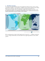
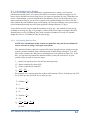
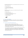
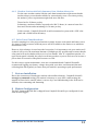
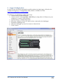
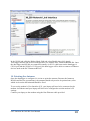
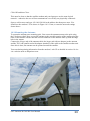
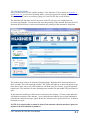
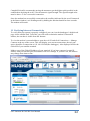
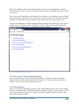
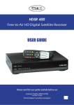
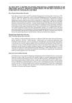
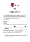
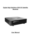
INSTRUCTION MANUAL SAT-Inmarsat-BGAN-Kit Satellite Modem Kit Hughes 9502 BGAN M2M SAT-Inmarsat-B GAN-Kit User Manual Revision: Dec 2012 Copyright © 1990 - 2012 1 Campbell Scientific Australia Pty Ltd Warranty and Assistance The MODEL SAT-INMARSAT-BGAN-KIT SATELLITE MODEM KIT is warranted by CAMPBELL SCIENTIFIC AUSTRALIA Pty Ltd. to be free from defects in materials and workmanship under normal use and service for twelve (12) months from date of shipment unless specified otherwise. Batteries and Antennas have no warranty. CAMPBELL SCIENTIFIC AUSTRALIA Pty Ltd’s obligation under this warranty is limited to repairing or replacing (at CAMPBELL SCIENTIFIC AUSTRALIA Pty Ltd.'s option) defective products. The customer shall assume all costs of removing, reinstalling, and shipping defective products to CAMPBELL SCIENTIFIC AUSTRALIA Pty Ltd. CAMPBELL SCIENTIFIC AUSTRALIA Pty Ltd will return such products by surface carrier prepaid. This warranty shall not apply to any CAMPBELL SCIENTIFIC AUSTRALIA Pty Ltd. products which have been subjected to modification, misuse, neglect, accidents of nature, or shipping damage. This warranty is in lieu of all other warranties, expressed or implied, including warranties of merchantability or fitness for a particular purpose. CAMPBELL SCIENTIFIC AUSTRALIA Pty Ltd. is not liable for special, indirect, incidental, or consequential damages. Products may not be returned without prior authorization. The following contact information is for Australia and International customers residing in countries served by CAMPBELL SCIENTIFIC AUSTRALIA Pty Ltd. directly. Affiliate companies handle repairs for customers within their territories. Please visit www.campbellsci.com to determine which Campbell Scientific company serves your country. When returning equipment to CAMPBELL SCIENTIFIC AUSTRALIA for repair, a Customer Return Materials Authorization (CRMA) form should be completed and included with the shipment. The CRMA form will provide details that will allow our repair and accounts staff to process the repair more quickly. These details include the fault description for each piece of equipment that is being returned, the phone number and email address for the contact person, shipping and billing addresses and any special shipping requirements for the return of the repair. To obtain a Customer Return Materials Authorization (CRMA) form and more information on repair procedures contact CAMPBELL SCIENTIFIC AUSTRALIA Pty Ltd., phone (07) 4401 7700 or email [email protected]. After a member of our Technical Sales & Support team determines the nature of the problem, a CRMA form will be sent to you. CAMPBELL SCIENTIFIC's shipping address is: CAMPBELL SCIENTIFIC AUSTRALIA Pty Ltd Attn: Repairs Department 411 Bayswater Road Garbutt, QLD 4814 Australia SAT-Inmarsat-B GAN-Kit User Manual 2 SAT-Inmarsat-B GAN-Kit User Manual 3 Contents 1 Satellite Coverage ............................................................................................................................7 2 Specifications ...................................................................................................................................8 3 Features ............................................................................................................................................8 4 Physical Description ........................................................................................................................9 5 Datalogger Ethernet Interfaces ....................................................................................................10 6 Power Considerations ...................................................................................................................10 6.1 Power Specifications ..................................................................................11 6.2 GPIO Power Control ..................................................................................11 6.3 Calculating Power Budget .........................................................................12 6.3.1 Calculating Battery Size ..............................................................................12 6.4 Typical Power Budgets ..............................................................................13 6.4.1 Weather Station with Daily Summary Data ................................................13 6.4.2 Weather Station with Daily Summary Data, Modem Always On..................................................................................................14 6.5 Solar Panel Considerations ........................................................................14 7 Note on Installation .......................................................................................................................14 8 Modem Configuration ...................................................................................................................14 9 Logger Configuration ...................................................................................................................15 9.1 NL120 or NL115 Interface ........................................................................16 9.2 NL200 Interface .........................................................................................16 10 Pointing the Antenna ....................................................................................................................18 10.1 .............................................................. Network Configuration in Windows 7............... 10.2 ........................................................... Network Configuration in Windows XP............... 10.3 ......................................................................................... Mounting the Antenna............... 10.4 .......................................................................................................Pointing Mode............... SAT-Inmarsat-B GAN-Kit User Manual 4 11 Verifying Internet Connectivity ...................................................................................................22 12 Restoring PC Networkig Settings.................................................................................................23 13 Programming .................................................................................................................................23 14 Troubleshooting .............................................................................................................................24 SAT-Inmarsat-B GAN-Kit User Manual 5 FIGURE 1-1 INMARSAT BGAN COVERAGE MAP. IMAGE CREDIT GROUND CONTROL ................................................... 7 FIGURE 4-1 SIM DOOR SIDE OF THE BGAN-M2M .................................................................................................... 9 FIGURE 4-2 ANTENNA CONNECTOR SIDE OF THE BGAN-M2M ................................................................................ 10 FIGURE 9-1 CONNECTION TO DATA LOGGER USING DEVICE CONFIGURATION UTILITY............................................. 15 FIGURE 9-2 CONNECTION TO NL200 USING DEVICE CONFIGURATION UTILITY ........................................................ 18 FIGURE 10-1 ANTENNA MOUNT ATTACHED TO MOUNTING POLE ............................................................................. 20 FIGURE 10-2 COARSE ANTENNA POINTING INFORMATION ....................................................................................... 21 FIGURE 11-1 EXTERNAL IP ADDRESS OF THE SATELLITE MODEM ............................................................................ 22 FIGURE 11-2 EXAMPLE DATALOGGER WEB PAGE ................................................................................................... 23 SAT-Inmarsat-B GAN-Kit User Manual 6 1 Satellite Coverage The Inmarsat Broadband Global Area Network (BGAN) satellite network consists of three geostationary satellites: I-4 Asia Pacific, I-4 EMEA and I-4 Americas which provide satellite data services around the world. The advantage of a geostationary satellite over a geosynchronous satellite is that a geostationary satellite does not change its position in the sky, allowing terminals to use much lower transmission power combined with a directional antenna, which makes low power satellite services feasible. Figure 1-1 Inmarsat BGAN Coverage Map. Image credit Ground Control Due to sending and receiving its radio signals on the L band (1518 – 1675MHz), the BGAN service is largely unaffected by rain fade which causes signal degradation in some satellite systems. SAT-Inmarsat-B GAN-Kit User Manual 7 2 Specifications Transmit Frequency: 1626.5 MHz – 1675MHz Receive Frequency: 1518MHz - 1559MHz GPS Frequency: 1574.42MHz – 1576.42MHz Modem Weight: 1.2Kg Modem Dimensions: 385mm x 385mm x 33mm Operating Temperature Range: -40°C to 75°C Storage Temperature Range: -55° to 75°C Humidity Tolerance: 95%RH at 40°C Modem IP Rating: IP40 Antenna IP Rating: IP65 Input Voltage: 12VDC or 24VDC nominal Power Consumption: Transmit – 20W Peak Narrow Beam Without Transmit – 4W Idle (Regional Beam) - <1W Sleep (wake on packet) <10mW at 12V Sleep (GPIO) <3mW at 12V SIM Card Type: USIM 3 Features The SAT-Inmarsat-BGAN-Kit consists of a Hughes 9502 modem (marketed as the BGANM2M). The BGAN-M2M is specifically designed for long-term unsupervised operation with low power consumption. The modem is supplied configured for operation with Campbell Scientific dataloggers as well as all the necessary cables for connection. Note that the Campbell data logger will also require an NL120 or NL200 Ethernet interface, depending on the datalogger model. See Section 5 for more information. The full list of parts provided with the kit is: Preconfigured BGAN-M2M Modem Battery Cable GPIO cable for activating Sleep mode Ethernet cable to connect modem to data logger Headphones for pointing antenna using 3.5mm audio socket 10m antenna cable with N-TNC connector Passive square panel antenna Antenna pole mount SAT-Inmarsat-B GAN-Kit User Manual 8 When connected to a Campbell Scientific datalogger with a custom program, the SATInmarsat-BGAN-Kit will allow your station to: Send and receive emails Upload data to an FTP site Send SMS messages Send and receive IP data 4 Physical Description The satellite modem supplied with the SAT-Inmarsat-BGAN-Kit has the following interfaces and controls on the exterior of the unit: SIM Door PWR GPS NET LED LED LED Audio Function Socket Button USB Socket Figure 4-1 SIM Door side of the BGAN-M2M Sim door: Remove this to insert or replace the modem’s Inmarsat SIM card. A Phillips head screwdriver is supplied with the modem kit for this purpose. PWR, GPS and NET LEDs: See manufacturer’s manual for details on the status LEDs. Audio Socket: Connect headphones to this 3.5mm audio socket when the modem is in Pointing Mode to hear tones which increase their pitch as the received signal strength increases. Function Button: Used for placing the modem in Pointing mode as well as resetting the modem. USB Socket: Used for Ethernet over USB, allowing a PC to access the modem’s web UI, AT commands and upgrade the modem’s firmware. SAT-Inmarsat-B GAN-Kit User Manual 9 Antenna Connector GPIO DB9 Ethernet Power Figure 4-2 Antenna Connector side of the BGAN-M2M Antenna Connector: The antenna cable will connect to the modem’s TNC antenna connector with the supplied N-TNC adaptor. GPIO DB9: Used in Campbell Scientific systems to place the modem in sleep mode. Ethernet: The main data interface for the modem. The datalogger will connect to the modem on this port using an NL120 or NL200 Ethernet interface. Power Supply: Suitable for either 12VDC or 24VDC nominal power sources. Due to its current drain, Campbell Scientific recommends powering the modem directly from a battery or regulator instead of a datalogger’s 12V or SW12 channels. 5 Datalogger Ethernet Interfaces The SAT-Inmarsat-BGAN-Kit requires a datalogger with an Ethernet interface. Campbell Scientific offer three Ethernet interfaces for our data loggers. The NL120 is a simple Ethernet interface which connects to the peripheral port of some of our data loggers. The NL115 is an NL120 with the addition of a compact flash storage module for extending datalogger memory. The NL200 is an Ethernet peripheral which connects to the datalogger via CS I/O. The list of dataloggers and suitable Ethernet interfaces is below: Suitable Interfaces Datalogger CR800/CR850 NL200 CR1000 NL120/NL115 CR3000 NL120/NL115 6 Power Considerations Satellite modems are generally considered to be high-powered devices for remote installations due to their need to project radio signals into space. The Inmarsat-BGAN modem is a highly power efficient device for a satellite modem, however a station’s power budget should still be carefully considered when incorporating this modem into a station’s design. SAT-Inmarsat-B GAN-Kit User Manual 10 6.1 Power Specifications The modem’s power specifications are: Activity Type Transmitting Narrow Beam without Transmit Idle (Regional Beam) Sleep (Wake on Packet) Sleep (GPIO) Power When this will occur Consumption <20W The modem will be in this state when actively transmitting data. Dependant on how often datalogger sends data. For most stations, has a duration of <5 min per day to send data recorded once daily. 4W The mode will be in this state when it has recently been active but is not currently transmitting. The modem will return to the Idle state after 100 seconds of inactivity. <1W The modem has satellite coverage but is not actively connected to its satellite. This is the default state after a long period of inactivity. <10mW at The Wake on Packet sleep mode is not generally used as 12V the GPIO sleep mode is recommended by Campbell Scientific to give better control of the modem’s power state. <3mW at 1V When the datalogger provides 5V on the GPIO cable included with the SAT-Inmarsat-BGAN-Kit, the modem will be forced into GPIO sleep mode, where power consumption is negligible. Campbell Scientific recommends this be done with the logger’s control ports under program control to minimise power consumption. 6.2 GPIO Power Control Campbell Scientific recommends only powering the satellite modem for part of the day, one hour per day or ten minutes per hour to minimise power consumption. Powering the modem down during night time on solar powered stations may also be worth considering. To achieve this, the SAT-Inmarsat-BGAN-Kit includes a GPIO cable with red and black leads at one end and a 9-pin connector on the other. Connecting the red lead to a datalogger control port and the black to a G port on the datalogger will cause the modem to sleep whenever that control port is turned on (“set”) by the datalogger’s program. This is usually done using the PortSet instruction in CRBasic. When the control port is set to low, the modem will leave sleep mode and begin its power-up process. Once this process is complete the modem will attempt to re-establish a link to its satellite. Please allow 90 seconds for this process to complete before attempting communications when writing datalogger programs to control modem power. Campbell Scientific offers programming services for our data loggers as well as CRBasic training courses, contact your local Campbell Scientific agent for more information. SAT-Inmarsat-B GAN-Kit User Manual 11 6.3 Calculating Power Budget In order to calculate solar panel and battery requirements for a station, you’ll need to calculate how much power you expect your station to consume (usually averaged over 24 hours), then calculate how much solar power you expect to generate in a day. With these two pieces of information, you can calculate how much battery power you’ll need to keep your station running as long as you need it to (typical solar systems budget to be able to run for 7 days without any sun) and how large a solar panel you’ll need to recharge your system after a period without generating any solar power(typical recharge allowed is 3 days). You will also need to keep in mind the insolation of your site – the amount of solar energy available on average per day. For example, a station in the Red Centre or northern Western Australia may receive 6 kWhrs/m2/day while a station in southern Victoria or Tasmania might only receive 2.5 kWhrs/m2/day of solar energy. 6.3.1 Calculating Battery Size NOTE: The calculations in this section are guidelines only and do not include all factors relevant to sizing a solar powered system. The amount of battery capacity a system will require depends on how much power the system consumes and how long it should operate without being recharged.. You will first need to estimate the daily power consumption of your system in watts (W). To do this, you will need to estimate the amount of time per day the each device in your system will be in each of its power states. Tx Hours per day the device will use this much power(h ) Px Power consumed by device(W ) PD Power consumed in a day(W ) PT PT 1 1 2 2 ... 24 24 For example, for a system where the modem will consume 1W for 20 mins per day, 4W for 30 mins per day and 20W for 10 mins per day, PD 1 T1 20mins h 3 P1 1 T2 30mins 1 h 2 P2 4 1 T3 10mins h 6 P3 20 1 13 4 12 20 16 24 24 24 0.236W PD SAT-Inmarsat-B GAN-Kit User Manual 12 The following formula will allow you to calculate battery capacity necessary for your system in amp-hours (Ah) B battery capacity ( Ah) PD daily power consumption (W ) A days of autonomy required (days ) B 2 PD A Now that you have battery capacity, you can calculate solar panel size using the following formula: B battery capacity ( Ah) PD daily power consumption (W ) R days required to fully recharge battery (days ) I solar insolation ( kWh / m2 / day ) S solar panel rating (W ) B P R S I 6.4 Typical Power Budgets For a weather station with temperature, relative humidity, wind speed, wind direction, barometric pressure and solar radiation measurements, some typical power budgets are investigated below. 6.4.1 Weather Station with Daily Summary Data Turned on for 1 hour per day during the middle of the day. For that hour, the modem is expected, on average, to spend 20 minutes idle, 30 minutes in a narrow beam without transmitting, and 10 minutes transmitting. This means that the modem will consume 1W for 20 mins per day, 4W for 30 mins per day and 20W for 10 mins per day. For a system like this to operate for 7 days without sun and fully recharge after 3 days of sun, installed in a region which receives 4kWhrs/m2/day, Campbell Scientific would recommend a system with a 10W solar panel and a 7Ah lead-acid battery. Despite the modem’s relatively heavy power consumption, turning it off for most of the day minimises this effect. SAT-Inmarsat-B GAN-Kit User Manual 13 6.4.2 Weather Station with Daily Summary Data, Modem Always On For the same weather station with the same data transmission requirements but the modem always powered and available for connection by users a few times per day, the station’s power requirements might look more like this: Turned on for 24 hours per day. In that time, modem would be expected to be idle 22 hours, in a narrow beam for 1 hour and 30 mins and transmitting for 30 mins per day. In this scenario, Campbell Scientific would recommend a system with a 30W solar panel and a 24Ah lead-acid battery. 6.5 Solar Panel Considerations It can be tempting in a solar powered station to simply increase solar panel and battery size a few times in order to ensure sufficient power will be available to the station or to minimize maintenance visits. However, this technique is not always the best option. It is important to site your station well so that it will receive the maximum amount of sunlight per day possible and to ensure that the solar panel will not be shadowed by trees in a few months’ time. If a significant portion of a typical solar panel is shaded, the panel overall may produce no power and can even become a power drain if too much of the panel becomes covered. For this reason, regular maintenance visits are recommended and Campbell Scientific recommends logging your battery voltage along with your other environmental data and collecting that data regularly to ensure that your station is operating at peak performance. 7 Note on Installation Due to the remoteness of datalogger stations with satellite telemetry, Campbell Scientific strongly recommends testing your station’s telemetry at your office (when testing, the antenna will need to be outside where it can see sky) as troubleshooting in the field can be difficult, time consuming and frustrating. 8 Modem Configuration The SAT-Inmarsat-BGAN-Kit is shipped from Campbell Scientific pre-configured for use with our data loggers. SAT-Inmarsat-B GAN-Kit User Manual 14 9 Logger Configuration In order to route its IP traffic through the satellite modem, the data logger will need to be configured using Device Configuration Utility which is available free from https://www.campbellsci.com/downloads. To connect to your datalogger, follow these steps: 1. Connect power to your datalogger. 2. Connect your PC to the datalogger’s RS-232 port, using either a COM port on your computer or a serial to USB converter. 3. Open the Device Configuration Utility. 4. Select the COM port on your PC that you have connected to the datalogger. 5. Expand the Datalogger list. 6. Select the datalogger you need to connect to from this list. 7. Click Connect. Figure 9-1 Connection to Data Logger using Device Configuration Utility SAT-Inmarsat-B GAN-Kit User Manual 15 9.1 NL120 or NL115 Interface To configure a datalogger with NL120 or NL115 Ethernet interface, follow these steps: Connect to the datalogger as shown at the start of Section 8. Select the TCP/IP tab. Once this is done, enter the following settings: Setting Value Meaning IP Address 192.168.128.240 The modem has been configured by Campbell Scientific to automatically connect to a device with this IP address. Subnet Mask IP Gateway 255.255.255.0 The modem and data logger will be on a local area network with this subnet mask. 192.168.128.100 This is the IP address assigned to the satellite modem. This tells the datalogger to direct its IP traffic to this destination to be forwarded on to the Internet. DNS Server 1 8.8.8.8 The DNS settings tell the datalogger where to find a Domain Name System server for translating domain names (such as ftp.examplesite.com) to IP addresses (such as 123.123.123.123). 8.8.8.8 is a Google public DNS server. DNS Server 2 172.30.66.7 The DNS settings tell the datalogger where to find a Domain Name System server for translating domain names (such as ftp.examplesite.com) to IP addresses (such as 123.123.123.123). 172.30.66.7 is a DNS server hosted by Inmarsat for their own customers. To finalise these settings, click Apply. Your logger and Ethernet interface are now configured for use with the SAT-InmarsatBGAN-Kit. 9.2 NL200 Interface To configure a datalogger with NL200 Ethernet interface, follow these steps: Connect to the datalogger as shown at the start of Section 7. Select the CS I/O IP tab. If the NL200 is the only Ethernet interface connected to the datalogger, fill in these fields in the CS I/O Interface #1 section. If there are two Ethernet interfaces on the datalogger and this is the second, fill in these details in the Interface #2 section: SAT-Inmarsat-B GAN-Kit User Manual 16 Setting IP Address Value Meaning 192.168.128.240 The modem has been configured by Campbell Scientific to automatically connect to a device with this IP address. Subnet Mask 255.255.255.0 IP Gateway The modem and data logger will be on a local area network with this subnet mask. 192.168.128.100 This is the IP address assigned to the satellite modem. This tells the datalogger to direct its IP traffic to this destination to be forwarded on to the Internet. DNS Server 1 8.8.8.8 The DNS settings tell the datalogger where to find a Domain Name System server for translating domain names (such as ftp.examplesite.com) to IP addresses (such as 123.123.123.123). 8.8.8.8 is a Google public DNS server. DNS Server 2 172.30.66.7 The DNS settings tell the datalogger where to find a Domain Name System server for translating domain names (such as ftp.examplesite.com) to IP addresses (such as 123.123.123.123). 172.30.66.7 is a DNS server hosted by Inmarsat for their own customers. To finalise these settings, click Apply. Once this is done the NL200 will need configuring to operate in Bridge Mode. To configured the NL200 to operate in Bridge Mode, follow these steps: Disconnect from the datalogger. Connect power to the NL200 interface using the power cable provided. You should see the POWER light glow solid red. Open Device Configuration Utility. Expand the Network Peripheral section and select NL200. If you have not already done so, follow the link in the Device Configuration Utility window to install the USB drivers for the NL200. Connect the supplied the NL200 to your PC using the supplied USB cable. In the Communications Port field, click the “…” button and select the new virtual COM port used for the NL200. If properly installed, this will display as NL200 (COMnm) where nm is a number assigned by Windows. Press Connect. SAT-Inmarsat-B GAN-Kit User Manual 17 Figure 9-2 Connection to NL200 using Device Configuration Utility In the NL200 tab, click the Bridge Mode field and select Enable, then click Apply. Your logger and NL200 are now configured for use with the SAT-Inmarsat-BGAN-Kit. Once the data logger and NL200 are connected (usually via SC12 cable between the datalogger’s CS I/O port and the NL200’s CS I/O port), the data logger will be able to connect to Ethernet devices such as the SAT-Inmarsat-BGAN. 10 Pointing the Antenna Once the datalogger is configured, it is time to point the antenna. Because the Inmarsat BGAN satellites are geostationary, the antenna should only need to be pointed once, after which its elevation and azimuth should be fixed. To access the modem’s User Interface (UI), your laptop will need to be connected to the modem via Ethernet and your laptop will need to be configured to suit the modem’s IP settings. Connect your laptop to the modem using the blue Ethernet cable provided. SAT-Inmarsat-B GAN-Kit User Manual 18 10.1 Network Configuration in Windows 7 Press the Start button and type “View Network Connections” without double quotes in the search window. Press enter. You will see a collection of the network interfaces your laptop possesses. Right click the Local Area Connection and select Properties. Once the Local Area Connection Properties window appears, select Internet Protocol Version 4 (TCP/IPv4) and click Properties. The Internet Protocol Version 4 (TCP/IPv4) Properties window will appear. You need to note your current settings so you can restore them later. If “Obtain an IP address automatically” is selected, write this down. If there are already numbers in the IP address, subnet mask and default gateway, write these down as they appear so you can restore them later. Once these have been recorded, click the “Use the following IP address” button and fill in these settings: IP address: 192.168.128.200 Subnet mask: 255.255.255.0 Default gateway: 192.168.128.1 Click OK and then Close. This must be done so that the satellite modem and your laptop are on the same logical network – otherwise the two will not communicate even if they are physically connected. Open a web browser and type 192.168.128.100 in the address bar then press enter. You should see the modem’s UI as in Figure 10-2. If not, re-enter the network settings shown above. 10.2 Network Configuration in Windows XP Click the Start button and select Control Panel. From here, go to Network Connections, then right click Local Area Connection and select Properties. Select Internet Protocol (TCP/IP) and click Properties. The Internet Protocol (TCP/IP) Properties window will appear. You need to note your current settings so you can restore them later. If “Obtain an IP address automatically” is selected, write this down. If there are already numbers in the IP address, subnet mask and default gateway, write these down as they appear so you can restore them later. Once these have been recorded, click the “Use the following IP address” button and fill in these settings: IP address: 192.168.128.200 Subnet mask: 255.255.255.0 Default gateway: 192.168.128.1 SAT-Inmarsat-B GAN-Kit User Manual 19 Click OK and then Close. This must be done so that the satellite modem and your laptop are on the same logical network – otherwise the two will not communicate even if they are physically connected. Open a web browser and type 192.168.128.100 in the address bar then press enter. You should see the modem’s UI as shows in Figure 10-2. If not, re-enter the network settings shown above. 10.3 Mounting the Antenna To mount the antenna on a mounting pole, first secure the antenna mount to the pole using the U-bolts provided. Next, secure the antenna to the movable portion of the mount using the bolts on the antenna. Ensure that the coaxial connector on the antenna lines up with the large hole in the mount. Connect the N-type end of the antenna cable (the larger end with no adaptor) to the antenna and the TNC end (smaller end with adaptor attached) of the cable to the satellite modem unit. Once this is done, the antenna can be pointed toward the satellite. You can obtain pointing information from the modem’s web UI as detailed in section 10.4 or via a website such as dishpointer.com. Figure 10-1 Antenna Mount attached to Mounting Pole SAT-Inmarsat-B GAN-Kit User Manual 20 10.4 Pointing Mode Once you have access to the satellite modem’s User Interface (UI) as shown in Section 9.1 and Section 9.2, you can enter Pointing Mode. Once the appropriate settings have been set in Windows, the UI can be accessed by typing 192.168.128.100 into a web browser. The Satellite Info tab at the lower left corner of the UI will give you rough values for elevation and azimuth. You can then fine tune the pointing of the antenna. Because the SATInmarsat-BGAN-Kit uses a directional antenna, the pointing of this antenna is important. Figure 10-2 Coarse Antenna Pointing Information The modem now needs to be placed in Pointing mode. Hold down the function button for three seconds. This will restart the modem. The LEDs will light up as the modem powers up. Once this is done, the power LED (leftmost) will flash once per second – press the function button once. The modem will enter Pointing mode and the left and middle LED will flash in sync. In this state the earbuds provided can be connected to the modem’s 3.5mm socket and tones will help the pointing of the antenna – lower pitched tones indicate lower signal and higher pitched tones indicate stronger signal. Before the antenna can be pointed however, it must be mounted on a pole. NOTE: It is not advisable to stand in front of the antenna when the modem is powered up due to the RF radiation it produces. SAT-Inmarsat-B GAN-Kit User Manual 21 Campbell Scientific recommends moving the antenna to get the highest pitch possible in the earbuds then checking the web UI for the numeric signal strength. The signal strength value must be above 53 for a successful connection. Once the modem has successfully connected to the satellite (indicated by the word Connected in the Status window), exit Pointing mode by holding the function button for three seconds. The modem will restart. 11 Verifying Internet Connectivity To verify that your system is properly configured, you can view the datalogger’s default web page via the satellite link. To do this, you will need to obtain the modem’s external IP address, the one that is visible from the Internet. To view the modem’s external address, open the web UI and click Connections -> Manage Contexts at the top of the screen. This will display your current connections, the only one active should be a connection to 192.168.128.240 (the datalogger). Also displayed will be the Global IP of your satellite terminal. Make a note of the Global IP address of your terminal. If you have requested a static IP address with your satellite plan, this address will never change. If you have not, this address may change from time to time. Figure 11-1 External IP Address of the Satellite Modem SAT-Inmarsat-B GAN-Kit User Manual 22 Remove the Ethernet cable from your laptop and reconnect it to the datalogger. Hold the function button for three seconds to restart the modem. Allow the modem at least 90 seconds to power up. If you have a wifi connection to the Internet on your laptop or a smartphone, type the Global IP you noted down earlier into your web browser. If you do not have an Internet connection available, it is advisable to have a colleage at the office check the connection for you. If you see the datalogger’s default web page after navigating to the Global IP, your system is configured correctly. If not, check the steps in sections 9 and 10 again and check that the Ethernet cable is connected to your datalogger and your modem. Figure 11-2 Example Datalogger Web Page 12 Restoring PC Networking Settings Once setup and testing of the satellite modem station is complete, return your network settings to their original state as noted down in Section 10. Until this is done, you will be unable to connect to your office Ethernet network. 13 Programming With use of a custom datalogger program, a SAT-Inmarsat-BGAN-Kit can be used to SMS alarms to a mobile number, send data and status messages via Email, send its data to an FTP server and push data to LoggerNet. Contact your local Campbell Scientific agent for more information on these options. SAT-Inmarsat-B GAN-Kit User Manual 23 14 Troubleshooting When setting up your satellite modem system, you may encounter some difficulties. This section will help you identify the cause of this difficulty. Symptom Solution No lights are visible on the modem unit Ensure that power is connected to the modem and that your battery has sufficient voltage. No power light on NL200 interface. Ensure power is connected to the NL200. Modem’s Web UI does not appear in browser Check your PC’s settings as described in Section 10.1 and Section 10.2. If these settings are correct, update your browser to the latest version. Cannot get signal strength above 53. Check coarse pointing information in modem UI and ensure that foliage etc does not obstruct the antenna’s view of the sky. Connection Status window in Web UI shows Registering… and never connects despite signal strength being above 53. Check that your SIM has been configured and activated, for Inmarsat SIM services contact Design9 on 02 4321 0727 or [email protected]. No Ethernet activity lights on the NL120 when it is connected to the modem. Check datalogger settings match those in Section 9.1. Disconnect power from the datalogger and reconnect it. No Ethernet activity lights on the NL200 when it is connected to the modem. Check datalogger and NL200 settings match those in Section 9.2. Disconnect power from the datalogger and reconnect it. Modem periodically powers down or stops responding Ensure that the modem is not connected to a datalogger which is powering it down under program control. Global IP never appears in Manage Contexts window Check your SIM card has been activated by the plan vendor and check that credit is available if it is a pre-paid SIM. SAT-Inmarsat-B GAN-Kit User Manual 24 Campbell Scientific Companies Campbell Scientific Australia Pty. Ltd. (CSA) PO Box 8108 Garbutt QLD 4814 AUSTRALIA www.campbellsci.com.au [email protected] PH: +61 7 4401 7700 Campbell Scientific Africa Pty. Ltd. (CSAf) PO Box 2450 Somerset West 7129 SOUTH AFRICA www.csafrica.co.za [email protected] Campbell Scientific do Brazil Ltda. (CSB) Rua Luisa Crapsi Orsi, 15 Butantã CEP: 005543-000 São Paulo SP BRAZIL www.campbellsci.com.br [email protected] Campbell Scientific Canada Corp. (CSC) 11564 - 149th Street NW Edmonton, Alberta T5M 1W7 CANADA www.campbellsci.ca [email protected] Campbell Scientific, Inc. (CSI) 815 West 1800 North Logan, Utah 84321 UNITED STATES www.campbellsci.com [email protected] Campbell Scientific Ltd. (CSL) Campbell Park 80 Hathern Road Shepshed, Loughborough LE12 9GX UNITED KINGDOM www.campbellsci.co.uk [email protected] Campbell Scientific Ltd. (France) Miniparc du Verger - Bat. H 1, rue de Terre Neuve - Les Ulis 91967 COURTABOEUF CEDEX FRANCE www.campbellsci.fr [email protected] SAT-Inmarsat-B GAN-Kit User Manual 25 Campbell Scientific Spain, S. L. Psg. Font 14, local 8 08013 Barcelona SPAIN www.campbellsci.es [email protected] Please visit www.campbellsci.com to obtain contact information for your local Campbell Scientific representative. SAT-Inmarsat-B GAN-Kit User Manual 26