1
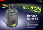
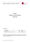
Manual Neon 2000 Family Neon Remote Terminals (NRT) 2018F Inmarsat Family This equipment has been tested and found to comply with the limits for a Class A digital device, pursuant to Part 15 of the FCC Rules in the U.S.A. These limits are designed to provide reasonable protection against harmful interference when the equipment is operated in a commercial environment. This equipment generates, uses, and can radiate radio frequency energy and, if not installed and used in accordance with the instruction manual, may cause harmful interference to radio communications. Operation of this equipment in a residential area is likely to cause harmful interference in which case the user will be required to correct the interference at his own expense. This equipment has been tested for compliance with European regulations as follows: Application of Council Directive: 2004/108/EC Standards to which Conformity is declared: EN-61000-6-1:2001 EN-61000-4-2:1995 EN-61000-4-3:1995 EN-61000-4-4:1995 EN-61000-4-6:1996 ENV-50204:1995 Any changes or modifications to this equipment not expressly approved by the manufacturer Unidata Pty Ltd could void the user’s authority to operate this equipment. Revision History File name/Revision Date Author & Change Details Unidata Manual - Neon 2000 Family Remote Terminals and Modules issue 4.0 25/09/2013 MP – Reformat for web site Unidata Manual - 2018F Inmarsat NRT Family - 28 05 2015.docx 28 05 2015 PC – Major Update Unidata Manual - 2018F Inmarsat NRT Family – 09 06 2015.docx 09 06 2015 PC – Reviewed Checked/ approved Copyright © Unidata Pty Ltd 2000-2013. All rights reserved. No part of this publication may be reproduced, transmitted, transcribed, stored in a retrieval system, or translated into any spoken or computer language, in any form or by any means. Electronic, mechanical, magnetic, optical, chemical, manual or otherwise, without prior written permission of Unidata Pty Ltd 40 Ladner St, O’Connor Western Australia 6163. Manual – 2018F Inmarsat Family NRTs TABLE OF CONTENTS 1.0 2.0 Neon Technology and Modules Overview ........................................................................ 3 1.1 Neon Remote Terminals ..................................................................................................... 4 1.2 Typical Neon Measurement System ................................................................................... 5 1.3 The Internet ......................................................................................................................... 5 1.4 Satellite Packet Data Service .............................................................................................. 5 1.5 NRT Internal Architecture .................................................................................................... 6 Summary of Neon Remote Terminals ............................................................................... 7 2018F Neon Remote Terminal – Ethernet with M2M Modem............................................. 8 2022E Neon Remote Terminal – 3G & USB with M2M Modem ......................................... 8 2.1 2.2 3.0 NRT LED indicator .............................................................................................................. 9 4.0 Satellite Airtime Resellers ................................................................................................ 10 5.0 Inmarsat NRT Satellite Antenna Pointing ....................................................................... 11 6.0 SIM Card Installation......................................................................................................... 13 7.0 NRT Installation ................................................................................................................. 17 Equipment Required .......................................................................................................... 17 Install or replace the NRT in the cabinet ........................................................................... 17 Connect and Turn ON Power ............................................................................................ 18 Point the Inmarsat Antenna ............................................................................................... 19 Confirm Satellite Connection ............................................................................................. 19 Initialise the NRT ............................................................................................................... 20 Confirm NRT has completed its Initialisation .................................................................... 21 7.1 7.2 7.3 7.4 7.5 7.6 7.7 8.0 9.0 Attaching an External Power Supply .............................................................................. 22 NRT Power Requirements ................................................................................................ 23 Internal Power ................................................................................................................... 23 External Power .................................................................................................................. 23 Internal Lithium Battery Life............................................................................................... 23 9.1 9.2 9.3 10.0 Troubleshooting ................................................................................................................ 24 NRT Not Communicating With Neon Server ..................................................................... 24 Check Hughes Connection Status and Signal Strength.................................................... 26 10.1 10.2 Unidata Manual - 2018F Inmarsat NRT Family - 09 06 2015.docx Page 1 Manual – 2018F Inmarsat Family NRTs References This manual should be read in conjunction with the associated StarlogV4 User Manual which describes the setting up of logging schemes for NRT terminals as well as all other Unidata Data loggers. This manual should also be read in conjunction with the Neon Server Documentation which is available in PDF form from the Unidata web site and is also available as help screens within the Neon Server system. The NRT Terminal User Manual, the StarlogV4 User Manual and the Neon Server User & Administrator Documentation form part of the documentation suite for the overall Neon System. Unidata Manual - 2018F Inmarsat NRT Family - 09 06 2015.docx Page 2 Manual – 2018F Inmarsat Family NRTs 1.0 NEON TECHNOLOGY AND MODULES OVERVIEW Neon is a system for collecting measurements from field instruments and transmitting the measurements to a central system for data recording, analysis, reporting and data transfer to other external systems. The Neon system also provides facilities for data collection, analysis, reporting and field measurement equipment and management within specified areas as defined by the system. Examples of this include country wide access, regional access and different access levels according to the rights and privileges of users, e.g. supervisor level, manager level, coordinator level and read only user level. The Neon System is suited to a range of uses such as environmental monitoring of remote instrumentation and automated industrial and utility metering. The Neon system may be offered on a system basis, with the customer purchasing the server and a software license from Unidata, or can be provided on an application service basis where the customer pays a service fee for Unidata to run the application on a Unidata central server. Overview of the Neon System Unidata Manual - 2018F Inmarsat NRT Family - 09 06 2015.docx Page 3 Manual – 2018F Inmarsat Family NRTs 1.1 Neon Remote Terminals There is a range of different Neon Remote Terminals available. This manual confines itself to presenting details of the Inmarsat family of NRTs. While the models may be different, and the interfaces available in various models are different, the basic operation of all Neon Terminals and Modules is the same. Inmarsat Neon Remote Terminals PC FTS Laptop Neon Server Inmarsat Satellite Ground Station Internet Local Area Network Modbus RTU Corporate Firewall Modbus Slave Sensor or PLC Typical Neon Measurement System Unidata Manual - 2018F Inmarsat NRT Family - 09 06 2015.docx Page 4 Manual – 2018F Inmarsat Family NRTs 1.2 Typical Neon Measurement System The figure above is an example of a Neon installation showing an NRT connected to a Water Level Instrument. Every day the NRT will send, via the Inmarsat satellite network to the Neon server, a “packet” of information containing the data in raw format. The Neon server extracts the raw data from the packet. The data is then stored on a secure server until the client accesses the data using a standard Web Browser. 1.3 The Internet The Internet provides the transport mechanism between the Neon Servers and the telecommunication provider gateways. This means that NRT units can be used anywhere in the world. 1.4 Satellite Packet Data Service There are several low earth orbit and equatorial orbit packet data service providers. The Ethernet Family of Satellite NRTs uses the Inmarsat system. The Inmarsat system provides IP (Internet Protocol) connectivity via the international Inmarsat GEO Satellite network from any location on the globe, except the Arctic and Antarctica. The Inmarsat system is used by Ethernet models of NRT. Unidata Manual - 2018F Inmarsat NRT Family - 09 06 2015.docx Page 5 Manual – 2018F Inmarsat Family NRTs 1.5 NRT Internal Architecture The NRT Internal architecture is shown below. It contains two discrete sections, A LOGGER section where the terminal connects to the field transducers and the logging scheme, scan rates and diagnostics are managed. The StarlogV4 support software allows a user to generate a logger scheme which defines transducer information, logging scan rates, logger interval etc and various engineering unit definitions. These files are called, for example the LDR and KBD files. A COMMUNICATOR section which deals with communications to the server. This section contains, for example, a scheduler component and the modem component, either a Cellular Network modem or a Satellite Network modem. The communicator manages functions such as the reporting interval, the number of communications attempts per communications session, etc. The StarlogV4 support software allows a user to generate a configuration file for the Communicator section, called an FPO file in which the user sets the required communications parameters. Unidata Manual - 2018F Inmarsat NRT Family - 09 06 2015.docx Page 6 Manual – 2018F Inmarsat Family NRTs 2.0 SUMMARY OF NEON REMOTE TERMINALS Neon Remote Terminals (NRT units) are small, ultra-low power microprocessor-based devices designed to collect data from data loggers and SDI-12 instruments. This data is then sent via Cellular Networks or Satellite packet data to a Neon server on a programmed schedule or as required for alerts. The NRT also incorporates a fully-programmable data logger so that simple analogue and digital signals may be directly connected and recorded. NRTs are classified according to the communications network over which they communicate. That is as either: Terrestrial (Cellular), Satellite (Globalstar or Inmarsat) or Ethernet. There are many different models of Neon Metering Modules. Plastic case models are referred to as Neon Remote Terminals (NMMs), Plastic case models with an LCD are referred to as Neon Remote Modules (NRMs) and Metal enclosure models are referred to Neon Remote Terminals (NRTs). This manual refers to all NMMs/NRMs/NRTs as NRTs because all 2018F’s are NRTs. All Neon Remote Terminals are small self-contained units in compact cases that connect to sensors in the field, collect readings from those sensors and transmit the collected data to a central Neon server. The type of network over which the collected data is transmitted varies from model to model. The Neon central server system can be provided either on a Neon Data Service basis or on a Neon Client System basis. Both provide a central computer system to monitor and receive data from many Neon Remote Terminals in the field. All Neon Remote Terminals are designed to automate collection of remote data from environmental monitoring, industrial measurements and utility metering via a communications network from any location within the network coverage area. Fully bi-directional communications are possible via the Neon server. Data can be collected directly and the Neon module can be programmed from any internet connection. The Neon modules also support integrated logging or automated collection of data from an external data logger. All Neon Remote Terminals utilise built-in modems that support packet data. They have long battery life and low operating costs through use of advanced microcontroller technology. All Neon Remote Terminals provide Input /Output functions as standard, including analog and digital inputs and SDI-12 data logger interface. There is also Modbus support via a partial implementation of the Modbus protocol, which allows for reading from and writing to specific registers within the Modbus RTU on an RS485 connection. Further details are available on request. Unidata Manual - 2018F Inmarsat NRT Family - 09 06 2015.docx Page 7 Manual – 2018F Inmarsat Family NRTs 2.1 2018F Neon Remote Terminal – Ethernet with M2M Modem The 2018F Ethernet NRT with M2M Satellite Modem is a small self-contained metal cased Neon Remote Terminal that communicates with the Neon server via the Inmarsat satellite network. 2.2 2022E Neon Remote Terminal – 3G & USB with M2M Modem The 2022E 3G & USB NRT with Satellite M2M Modem is a small self-contained metal cased Neon Remote Terminal that communicates with the Neon server via either a 3G cellular network or via the Inmarsat satellite network. This allows connection to the Neon server from any location on the globe with either cellular telephone network access or satellite access. The 2022E NRT can automatically fail over to the other interface when one route fails. The Ethernet port can also be used to connect a Unidata high resolution camera. The USB port can be used to connect additional supported accessories. Unidata Manual - 2018F Inmarsat NRT Family - 09 06 2015.docx Page 8 Manual – 2018F Inmarsat Family NRTs 3.0 NRT LED INDICATOR The simplest indicator is the red LED which is visible in the window of the unit. On first power on the LED will be brightly on (not flashing) for 10 seconds indicating the unit is in the process of being reset. Do not interrupt this initial start-up process. If the initial start-up is interrupted you should power down, wait a few minutes, and then power up again. Slow flashing bright LED. One flash per second indicates the NRT is establishing a network connection via the internal modem. This process takes approximately 10 to 20 seconds. Fast flashing bright LED. 3 to 5 flashes per second indicate the PPP session is running and the NRT is communicating through the internal modem to the host server. If the NRT is programmed to hold the PPP session open all the time, i.e. the always on mode, the LED will continue to flash at this rate. Slow brief flashing (dim) LED. One dim flash every Scan Interval (typically every 5 seconds) indicates normal NRT operation (sleeping). No communication is in progress. The NRT has been programmed to log data and will only establish communications at the defined reporting interval with which it has been configured. Very occasional bright single flash. This indicates the scheme is actively logging rather than sleeping at that particular time. If you have a scheme which has a 5 second Scan rate and a 1 minute Log Interval, you will see dim flashes (indicating sleep) every 5 seconds (i.e. every scan interval), then one bright flash on the minute, indicating that a log is in progress. This cycle repeats at the Log Interval, hence the LED will brightly flash every 1 minute. When the NRT periodically communicates with the Neon server, the LED will slowly flash as it establishes a network connection, then quickly flash while it actually communicates with the Neon server (uploads log data, downloads its scheme, processes queued commands, etc), then slowly flash as it disconnects from the network The durations of each stage will vary according to the telemetry type of the NRT and how much data is transferred between the NRT and Neon server. If an NRT has been configured on the Neon server to Auto Cold Boot, then after the 10 second start up illumination, the NRT will immediately start a normal comms cycle, as previously described, following the normal slow flashing, fast flashing, slow flashing cycle. Unidata Manual - 2018F Inmarsat NRT Family - 09 06 2015.docx Page 9 Manual – 2018F Inmarsat Family NRTs 4.0 SATELLITE AIRTIME RESELLERS Inmarsat airtime needs to be purchased from one of the many Inmarsat resellers in Australia. Unidata can assist in discussing requirements with airtime providers. Unidata does not recommend any particular one. Unidata purchases airtime from the highest tier reseller and they are the most likely to offer the best airtime pricing. Please contact Unidata for a referral. Unidata Manual - 2018F Inmarsat NRT Family - 09 06 2015.docx Page 10 Manual – 2018F Inmarsat Family NRTs 5.0 INMARSAT NRT SATELLITE ANTENNA POINTING Inmarsat satellites are geostationary satellites that appear to not move in the sky. This means that provided the satellite antenna is correctly pointed, NRT access to an Inmarsat satellite is essentially guaranteed. Inmarsat M2M satellite modem antennas are very directional in order to achieve high gains and therefore better signal strength. It is therefore crucial that Inmarsat satellite antennas are properly pointed. There are web sites on the internet that provide satellite pointing tools. There are also iPhone and Android apps to help in this regard. One useful website is http://www.dishpointer.com/. The site allows you to enter the site’s location (as an address, GPS coordinates or using the Google maps applet) and specify the satellite that you are trying to locate. In Australia, the satellite to select in the dropdown list is the “143.5E INMARSAT 4-F1” satellite. The web site will then indicate the correct antenna elevation and azimuth to use. See example picture below. Unidata Manual - 2018F Inmarsat NRT Family - 09 06 2015.docx Page 11 Manual – 2018F Inmarsat Family NRTs Another method of pointing the satellite antenna is to use the Hughes M2M modem’s built in web interface. The Hughes M2M modem has an inbuilt GPS receiver, so provided that the modem has a GPS fix, it will display the received signal strength and the optimal antenna elevation and azimuth. The signal strength indication can be used to fine tune the antenna direction for maximum received signal. It is not necessary to use both antenna pointing methods - either will do. Unidata Manual - 2018F Inmarsat NRT Family - 09 06 2015.docx Page 12 Manual – 2018F Inmarsat Family NRTs 6.0 SIM CARD INSTALLATION This procedure describes the installation of a data SIM into Hughes satellite modem. When the Unidata satellite system is delivered to site it may be necessary for the commissioning personnel to fit the data SIM card. This is a simple process and will be described below with the aid of several pictures. Process The Hughes satellite modem requires the installation of the data SIM prior to operation. This is best done prior to the system being powered up. Locate the Hughes modem in the system. Shown with red box Unidata Manual - 2018F Inmarsat NRT Family - 09 06 2015.docx Page 13 Manual – 2018F Inmarsat Family NRTs Unscrew the mounting hardware to release the Hughes satellite modem. The mounting hardware may not always be the same in the above photo. Locate the SIM card cover and remove screw to access the SIM card holder. Be careful not to pull on any connected cabling. Unidata Manual - 2018F Inmarsat NRT Family - 09 06 2015.docx Page 14 Manual – 2018F Inmarsat Family NRTs Hughes modem with the SIM card cover removed. Insert the SIM card with the notch orientated as above. Unidata Manual - 2018F Inmarsat NRT Family - 09 06 2015.docx Page 15 Manual – 2018F Inmarsat Family NRTs Ensure the SIM card is fully seated in the holder as in the picture above. Re-assemble the system using a reverse of the above procedure. Ensure all cabling is still intact and that no wires have been pulled out of their connectors. Once the satellite modem is mounted back into position, the system set up and commissioning documentation can be followed. Unidata Manual - 2018F Inmarsat NRT Family - 09 06 2015.docx Page 16 Manual – 2018F Inmarsat Family NRTs 7.0 NRT INSTALLATION The following section provides guidance through the steps needed to bring these Satellite telemetry systems on line in the field to commission Neon Remote Terminal systems. Normally an NRT would have been initialised in the Unidata factory as part of the system manufacturing process and would already be set up on a Neon Server. The system should start working normally when power is applied in the field. This document also contains diagnostics procedures that can be followed should the system not automatically come on line. In order to perform the diagnostics tasks, StarlogV4 software must be installed onto a field laptop for use in the event the system has not already been initialised onto a specific Neon server. A separate companion document describes how to install and use StarlogV4. Whenever problems are encountered during this commissioning process, Unidata should be rung for assistance. 7.1 Equipment Required Ethernet cable Serial cable and USB-to-RS232 converter Compass Field Laptop with StarlogV4 software 7.2 Install or replace the NRT in the cabinet Be sure to connect all cables. Connect the FTS to the NRT. Connect Power to the FTS Ensure all appropriate wiring is connected to the FTS. Connect an Ethernet cable from the NRT to the Hughes satellite modem. Open up the NRT case / take the lid off the case and remove the insulating tabs on the lithium batteries (this allows the NRT to use the lithium batteries for emergency power). Make sure the Normal/Config switch is in the correct position. Solar / low powered systems: switch is in NORMAL position. Gen set / high powered systems: switch is in CONFIG position. Unidata Manual - 2018F Inmarsat NRT Family - 09 06 2015.docx Page 17 Manual – 2018F Inmarsat Family NRTs 7.3 Connect and Turn ON Power Turn on Power to the NRT and Hughes satellite modem. The NRT Power switch will usually be a DIN rail mounted switch. Check that the red LED light is lit on the grey terminal, this will indicate the satellite unit has 24 Volts power. Unidata Manual - 2018F Inmarsat NRT Family - 09 06 2015.docx Page 18 Manual – 2018F Inmarsat Family NRTs 7.4 Point the Inmarsat Antenna The Inmarsat antenna is directional and must be pointed in the right direction. Refer to section 5.0 for details. 7.5 Confirm Satellite Connection When initially powered on or reset, the Hughes Modem’s three green LEDs will progress through a sequence of flashing and solid lights. The modem may also be reset by holding in the modem’s black Function (reset) button for 10 seconds. One can also briefly press and release the Hughes satellite modem’s Reset Button any time the LEDs are off to check the Hughes satellite modem’s status. The three LEDs should come on after a few seconds delay. Check the power by pressing the black Function (reset) button on the Hughes modem for 10 seconds. The three green LEDs should then come on in the following sequence: 1. Solid Power light indicates the unit has power. 2. The GPS light flashes while the unit attempts to acquire a GPS fix. The antenna does not need to be pointed correctly for this to succeed (as many GPS satellites are available) but the antenna must have a clear view of the sky. A solid GPS light indicates a GPS fix has been obtained. 3. The NET LED flashes as the modem attempts to connect to the Inmarsat satellite network. The antenna must be pointed correctly for a connection to occur. A solid NET light indicates the unit has connected to the Inmarsat satellite network. If the NET LED remains flashing, the instructions in section 5.0 Error! Reference source not found.should be followed to accurately point the Inmarsat antenna using the signal strength information measured by the Hughes modem itself. Unidata Manual - 2018F Inmarsat NRT Family - 09 06 2015.docx Page 19 Manual – 2018F Inmarsat Family NRTs 7.6 Initialise the NRT Resetting the NRT should ordinarily initialise the NRT onto a Neon server. Hold the NRT Reset button in for 10 seconds and then release the button. The NRT’s red LED (visible through clear window) should initially show a solid red light for 10 seconds and then follow the sequence in the table below. The initialisation sequence will take around 2 minutes to complete. LED Behaviour Duration Meaning Slow flashing 70 seconds Waiting for Hughes satellite modem to complete power on sequence and then connect to Neon server 20 seconds Loading configuration from and/or sending Log Data to the Neon server 15 seconds Disconnecting from Neon server Once a second Fast flashing Several times a second Slow flashing Once a second After initialisation has completed the red LED will flash dimly every 5 seconds indicating that the system is scanning its inputs and operating normally. Unidata Manual - 2018F Inmarsat NRT Family - 09 06 2015.docx Page 20 Manual – 2018F Inmarsat Family NRTs 7.7 Confirm NRT has completed its Initialisation The commissioning field staff should ring Unidata to confirm that data is being delivered into the Neon server. The NRT’s red LED will repeat the sequence in the table in the previous section every comms interval (typically every 5 minutes) according to the communications frequency configured on the Neon server. If the red LED takes an unusually long time to complete the Fast Flashing stage (longer than 20 or 30 seconds) then the NRT is having trouble connecting to the Neon server and the cause should be investigated by following the diagnostics procedure in a later section of this manual and preferably by ringing Unidata staff for assistance. Unidata Manual - 2018F Inmarsat NRT Family - 09 06 2015.docx Page 21 Manual – 2018F Inmarsat Family NRTs 8.0 ATTACHING AN EXTERNAL POWER SUPPLY This section describes the procedure for attaching an external power supply to the NRT. Remove the cover of the weatherproof enclosure and remove the NRT if a weatherproof enclosure is provided. Rubber self-sealing glands are provided in the base of the weatherproof enclosure for external wiring connections. To keep the enclosure weatherproof, all wires leading to the NRT must pass through these glands. Connect the wires from the external power supply to the field termination strip. connection points are +12V and GND. The Ensure all wires are firmly attached to the field termination strip and return the NRT to the weatherproof enclosure. Replace the cover of the weatherproof enclosure. Unidata Manual - 2018F Inmarsat NRT Family - 09 06 2015.docx Page 22 Manual – 2018F Inmarsat Family NRTs 9.0 NRT POWER REQUIREMENTS 9.1 Internal Power The 2018 family of NRTs require external power. However, internal Lithium batteries may be fitted to maintain the NRT’s logging functionality if external power is lost. Keep in mind that loss of external power might also prevent collection of data due to coincidental loss of power to the instrumentation and external sensors. 9.2 External Power If required the NMM can be powered by an external supply of 6 to 16VDC @ 2A peak (while transmitting) and 25mA (while receiving) and 30uA while on standby. Unidata recommends 12V 7.2AH SLA (Sealed Lead Acid) batteries as a good external supply. External instrumentation must be separately powered if more than 500uA is required. The download schedule is the largest consumer of power. The Continuous Drain Equivalent rating can be used to size the external power requirements and duration of external power supplies. However, external power sources should have an additional 100uA at 12V or 50uA at 6V continuous drain added, (due to parasitic losses in the NMM circuitry). The decision to use an external power supply should be based on the projected or known frequency of battery changes, i.e. if a high download schedule is required and frequent battery replacement is going to prove difficult or expensive, then an external power supply is desirable. 9.3 Internal Lithium Battery Life The Inmarsat family of NRTs can be fitted with 3 internal Lithium batteries. Battery life depends on the position of the internal Normal/Config switch. The internal Lithium batteries never provide power to the external Hughes modem. When the switch is in the Config position, the batteries only provide power to the internal logger and communications sections of the NRT. They do not power the internal router component or the external Hughes modem. When the switch is in the Normal position, the batteries provide power to the internal logger and communications sections of the NRT and the internal router component, which can be upwards of 250mA depending on the particular NRT model. Battery life is consequently quite long (up to 5 years) when the switch is in the Config position but is greatly reduced (one month) when in the Normal position. Should the internal Lithium batteries go flat while no external power is available, the NRT will lose its scheme, stop logging and lose all its previously logged data. The NRT will need to be re-initialised when power is restored. Unidata Manual - 2018F Inmarsat NRT Family - 09 06 2015.docx Page 23 Manual – 2018F Inmarsat Family NRTs 10.0 TROUBLESHOOTING 10.1 NRT Not Communicating With Neon Server Possible Causes Neon Remote Terminal Unit has a power problem. Ethernet connection between Neon Remote Terminal Unit and Hughes modem is poor or disconnected. Neon Remote Terminal has not connected to the server due to the satellite antenna being incorrectly pointed. Possible solutions Check to see that there is power connected to the system. The red LED light (highlighted by green box in picture below) will be flashing dimly every 5 seconds to indicate Neon Remote terminal unit is active. Check that there is a good connection between the Neon Remote Terminal Unit and Hughes satellite modem. This may have become loose in transit. Press in the NRT Reset button for about 2 seconds and then let go. This should turn on the blue Ethernet LED on the NRT and the red LED light on the NRT front panel. Unidata Manual - 2018F Inmarsat NRT Family - 09 06 2015.docx Page 24 Manual – 2018F Inmarsat Family NRTs The red LED light will start flashing brightly in the front panel window for approximately 2 to 3 minutes, following the sequence on page 20. This indicates that the Neon System is initialising. After initialisation has completed the red LED will flash dimly every 5 seconds to indicate that the system is scanning its inputs and operating normally. Unidata Manual - 2018F Inmarsat NRT Family - 09 06 2015.docx Page 25 Manual – 2018F Inmarsat Family NRTs 10.2 Check Hughes Connection Status and Signal Strength The laptop’s Ethernet port must first be configured to obtain an IP address automatically from the Hughes modem, which is configured to issue IP addresses using DHCP. On Windows 7, the TCP/IPv4 Properties can be accessed from Control Panel -> Network and Internet -> Network and Sharing Center, then selecting Change adapter settings from the left panel. Right click on the laptop’s Local Area Connection and select Properties from the context menu to open the Local Area Connection Properties dialog. Click on Internet Protocol Version 4 (TCP/IPv4) connection and then click the Properties button. Ensure that the “Obtain an IP address automatically” and “Obtain DNS server address automatically” radio buttons are selected and then press OK. Unidata Manual - 2018F Inmarsat NRT Family - 09 06 2015.docx Page 26 Manual – 2018F Inmarsat Family NRTs Unplug the Ethernet cable from the Hughes satellite modem and connect the Hughes satellite modem to the laptop’s Ethernet port using an Ethernet cable. Open a Web Browser and enter the IP address 192.168.1.35 into the address bar. Click on the Connections button at the top of the screen to open the Hughes modem’s Manage Contexts page. In the Connection Status area to the left of screen, check that the Signal Strength is greater than 55 in REGIONAL mode or greater than 65 in NARROW beam mode. Unidata Manual - 2018F Inmarsat NRT Family - 09 06 2015.docx Page 27 Manual – 2018F Inmarsat Family NRTs Check for Global IP under Connections > Manage Contexts if in Narrow Beam mode Unplug the laptop’s Ethernet cable from the Hughes satellite modem and re-plug the Ethernet cable from the NRT back into the Hughes satellite modem. Unidata Manual - 2018F Inmarsat NRT Family - 09 06 2015.docx Page 28