1
NAR-5650 Series
Communication Appliance
User′s Manual
Revision: 1.0
CE
This certificate of conformity of NAR-5650 series with actual required safety standards in
accordance with 89/366 ECC-EMC Directive and LVD 73/23 ECC
UL
This product meets all safety requirements per UL60950 standard.
CASWELL. Inc.
7F, No. 186, Jian-Yi Rd., Chung-Ho city, 235,Taipei,Taiwan,
R.O.C.
Headquarter: +886-2-5591-1999
FAX: +886-2-5591-1666
http://www.cas-well.com
Table of Contents
Chapter 1 Introduction ........................................................................................................... 2
1.1
About This Manual ............................................................................................................ 2
1.2
Manual Organization ......................................................................................................... 2
1.3
Technical Support Information .......................................................................................... 3
1.4
Board Layout..................................................................................................................... 3
1.5
System Block Diagram ...................................................................................................... 4
1.6
Product Specifications ....................................................................................................... 4
Chapter 2 Getting Started ...................................................................................................... 7
2.1
Included Hardware ............................................................................................................ 7
2.2
Before You Begin .............................................................................................................. 7
2.3
The Chassis ...................................................................................................................... 8
2.4
Open the Chassis.............................................................................................................. 8
2.5
Install 3.5” Hard disk .........................................................................................................9
2.6
Install EZIO .................................................................................................................... 10
2.7
Install a Different Processor ............................................................................................ 11
2.8
Install and Remove DIMM ............................................................................................... 13
2.9
Remove and Install Compact Flash Card........................................................................ 14
2.10
Remove and Install Battery ............................................................................................. 14
2.11
Ear Mount Kit Installation................................................................................................. 15
2.12
Hardware Configuration Setting ...................................................................................... 16
2.13
Use a Client Computer .................................................................................................... 18
Chapter 3 BIOS Setting ........................................................................................................ 20
BIOS Setup Information 20
Chapter 4 EZIO Programming Guide .................................................................................. 27
4.1
About EZIO3 ................................................................................................................... 27
4.2
Features 27
4.3
Technical Support Information ........................................................................................ 27
4.4
Mechanical Specification................................................................................................. 28
4.5
General Specification ...................................................................................................... 28
4.6
Product Outlook .............................................................................................................. 28
4.7
Interface Pin Assignment ................................................................................................ 28
4.8
Hardware installation....................................................................................................... 29
4.9
EZIO3 Function Command ............................................................................................. 30
4.10
Character Generator ROM (CGROM) ............................................................................ 33
4.11
Sample Codes................................................................................................................. 34
NAR- 5650 Series User’s Manual
1
Chapter 1 Introduction
1.1
About This Manual
This manual contains all required information for setting up and using the NAR-5650 series.
NAR-5650 provides the essential platform for delivering optimal performance and functionality in
the value communications appliance market segment. This manual should familiarize you with
NAR-5650 operations and functions. NAR-5650 series provide up to eight on-board Ethernet
ports to serve communication applications like Firewall, requiring up to twenty four Ethernet
ports(in 2U Chassis)to connect external network (internet), demilitarized zone and internal network.
NAR-5650 series overview:
Support 3000 series Xeon ,Dual Core Xeon, Quad Core Xeon CPU
Up to 8GB DDR2 667/800 DIMM
Up to four USB ports and One COM ports
Two SATA connectors for SATA HD
one CF card slot
Up to two PCI-E x8 interfaces(in 2U Chassis)
Provides absolute high flexibility of customized I/O configuration
Three sets and Generation 2.0 By-pass functions.
WARNING!
1. “CAUTION: DANGER OF EXPLOSION IF BATTERY IS INCORRECTLY REPLACED. REPLACE ONLY
WITH SAME OR EQUIVALENT TYPE RECOMMENDED BY THE MANUFACTURER. DISCARD USED
BATTERIES ACCORDING TO THE MANUFACTURER’S INSTRUCTIONS”
2. This guide is for technically qualified personnel who have experience installing and configuring system
boards. Disconnect the system board power supply from its power source before you connect/
disconnect cables or install/ remove any system board components. Failure to do this can result in
personnel injury or equipment damage.
3. Avoid short-circuiting the lithium battery; this can cause it to superheat and cause burns if touched.
4. Do not operate the processor without a thermal solution. Damage to the processor can occur in
seconds.
5. Do not block air vents. Minimum 1/2-inch clearance required.
1.2
Manual Organization
This manual describes how to configure your NAR-5650 system to meet various operating
requirements. It is divided into four chapters, with each chapter addressing the basic concept
and operation of this system.
Chapter 1:
Introduction. This section describes how this document is organized. It includes brief
guidelines and overview to help find necessary information.
Chapter 2:
Hardware Configuration Setting and Installation. This chapter demonstrated the
hardware assembly procedure, including detailed information. It shows the definitions
and locations of Jumpers and Connectors that can be used to configure the system.
Chapter 3:
This section describes how to use BIOS functions .
Chapter 4:
This section describes how to programming EZIO software.
NAR- 5650 Series User’s Manual
2
Any updates to this manual, would be posted on the web site:
http://www.cas-well.com/products/index.php
1.3
Technical Support Information
Users may find helpful tips or related information on Caswell's web site: http://www.cas-well.com A
direct contact to Caswell's technical person is also available. For further support, users may also
contact Caswell’s headquarter in Taipei or local distributors.
Taipei Office Phone Number: +886-2-55911999
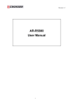
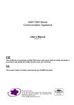
1.4
Figure 1-1
NAR- 5650 Series User’s Manual
Board Layout
Board Layout of NAR-5650 M/B
3
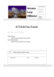
1.5
System Block Diagram
LGA775
Socket for
Xeon 3000
Conroe, Wolfdale
[ Module-C ]
1U/2U B/P with PCI-E x8
Interface for Advanced AP
- For Customized/Standard
Add-on cards.
- 10G Bypass
- Fiber Bypass
- Cavium Cards (RF-330)
[ 8 RJ45 GbE ports ]
-Cost Oriental Solution
-Up to 3 Bypass segments
DDR2 800/667
1333/1066/800
3210
PCI Slot
Up to
CF-Socket
BIOS/
SATA-2
DMI 2
ICH9R
40-pin IDE
connector
SATA-1
SATA-II
PCI-to-IDE
Controller
miniPCI
PCI32/33
PCI32/33
[ Module-B ]
PCI-E x8 Interface for
Advanced AP Expansions
- Dual 10G ports
- Up to 8 SFP GbE ports
- Up to 8 RJ45 GbE ports
- Compatible with ABN-card of
NAR-7090
PCI-E
GbE-0
PCI-E
GbE-2
PCI-E
GbE-4
PCI32
GbE-0
(82574)
(82574)
(82574)
(82541)
PCI-E
GbE-1
PCI-E
GbE-3
PCI-E
GbE-5
(82574)
(82574)
(82574)
PCI32
GbE-1
(82541)
Bypass 1
RJ45
Bypass 2
RJ45
RJ45
1.6
USBpin
---------
Bypass 3
RJ45
RJ45
RJ45
RJ45
RJ45
RJ45
Syste
m
Product Specifications
#
Requirement
Detailed Description
1
System
Description
NAR-5650 system series is single Xeon system based on Intel® 3210+ICH9R chipset with optional
configuration to meet market requirements in-between top-P4 and high-end Xeon platform segments.
It should be migration model of current NAR-5071, -5077 and -7050E system series.
Three basic series:
(1) 1U rackmount w/ single PSU – 1st priority.
(2) 1U rackmount w/ redundant PSU – design ready for project.
(3) 2U rackmount w/ redundant PSU – 2nd priority, for certain regional market.
2
CPU
Supports LGA 775 Server CPUs, including 3000 series Xeon and 6000, 8000, 9000 series desktop
CPUs. Core base cover up to 65nm Conroe, Kentsfield and 45nm Wolfdale and Yorkfield.
3
CPU Board
PPAP-3762VL with Intel® 3210 chipset
Board size: 304.8x381mm / 12”x15”
System
Memory
4 DIMM slot supports up to 8 GB
Supports un-buffered ECC DDR2 800/667
Power
Supply
Three form factor will be required: (1) 1U single (2) 1U redundant (3) 2U redundant.
Full range ATX PSU with total 300W power output will be required (depends on
4
5
power-budget).
AC On/Off switch is required.
Certification: CE, UL, 3C
Operating Mode: AT with power switch. ATX with power button.
Dimension: (1) 1U single PSU - 102(W) x 190(D) x 40 (H) mm
NAR- 5650 Series User’s Manual
4
#
Requirement
Detailed Description
(2) 1U redundant PSU - 106(W) x 400(D) x 40 (H) mm
(3) 2U redundant PSU - 105(W) x 310(D) x 80 (H) mm
6
Chassis
Form factor: 1U / 2U rack-mount chassis with a (rear) supporting bracket (trail) system
(kit).
To accommodate: M/B, EZIO-3, PSU, one 3.5” HDDs, advanced Ethernet I/O module
(ABN-458, ABN-668, ABN-522…), PCI-E add-on card which is connected through
backplane.
Chassis depth: (1) 1U w/ single PSU <18”.
(2) 1U w/ redundant PSU < 20”
(3) 2U w/ redundant PSU < 19”
7
PCI-E
Architecture
One PCI-E x8 from N/B (3210) to on-board golden-finger for direct connection with
proprietary PCI-E/PCIX add-on modules (ABN-series).
The other PCI-E x8 from N/B (3210) to golden-finger on left side for connection with PCI-
E/PCI-X backplane for expansion.
6 PCI-E x1 from S/B (ICH9R) are configured in two types (two mother boards)
- Connect directly to six PCI-E x1 GbE controller 82574 w/ RJ45 connector.
- 2 of the six lanes connect directly to PCI-E x1 Eth. Controller (82574) and the other 4
lanes are integrated to one PCI-E switch (PLX 8508) and connected to two 82571EB (x2
for each).
8
9
Ethernet
Expansion
slots
Onboard built with max. 8 GbE ports & 3 bypass segments:
12
VGA
Interface
13
Power
On/Off
operation
14
Front Panel
9
4 PCI-E x2 (82571) SFP + 2 PCI-E x1 (82574) RJ45 + 2 PCI32 (82541PI) ports, 1
bypass segments. (CPU-board PPAP-3762L-4410)
iAMT feature shall be supported by project.
Storage
2 PCI-E x2 (82571) SFP + 2 PCI-E x2 (82571) RJ45 + 2 PCI-E x1 (82574) RJ45 + 2
PCI32 (82541PI) ports, 2 bypass segments. (CPU-board PPAP-3762L-2620)
Two PCI-E x8 interfaces from N/B shall be configured as followed:
11
9
SATA & IDE
Interfaces
6 PCI-E x1 (82574) + 2 PCI32 (82541PI), 3 bypass segments. (CPU-board PPAP3762L-0830)
10
9
9
One PCI-E x8 golden finger on front-left of the CPU board for direct connection with
proprietary PCI-E add-on modules (ABN-series).
9
The other PCI-E x8 golden-finger on left edge for connection with PCI-E/PCI-X
backplane for expansion.
One onboard Mini PCI socket is required.
One standard PCI slot for testing and programming.
One IDE channel shall be converted from PCI bus and supports one Compact Flash Socket
and a 40-pin pin-header.
A jumper for device-selection between CF socket and 40-pin IDE connector of the IDE
channel is required.
The IDE interface shall support DMA mode.
Two SATA Interfaces on board with lockable connectors (B6210691)
HDD
System is equipped default with fixed HDD
Space for one 3.5” SATA HDD is required.
On board Type-1 CF socket for CF card.
By request the VGA feature can be implemented through MiniPCI Module. No onboard
VGA to be built.
A semi-cutting hole for standard D-Sub 15-pin VGA connector on chassis.
There should be an on/off switch on PSU itself or a separated on/off switch attached to PSU
to turn the PSU on/off; this switch is for AT mode operation.
There should be a toggle switch pin-header to allow ATX model operation.
There is an “always on” item in the BIOS. System will be powered up automatically while
power is resumed, if it is “on” before power failed.
Customer can use OS command to shut down system power.
More detailed Power on/off mode to be determined.
EZIO-III
8 RJ-45 connectors for PCI-E & PCI32 GbE interfaces. The four on LHS should be co-built
for RJ45 and SFP.
NAR- 5650 Series User’s Manual
5
#
Requirement
Detailed Description
Ethernet I/O sequence: from LHS to RHS.
One integrated connector with dual-USB connector and RJ45 connector for system
console, tab-down, no LED.
The Dual-USB connector should be optional.
Hardware Reset Button
Factory Default button (optional)
Reserved Power button for project inquiry.
LED: Signaling standard
System LED: Power, Data access.
Ethernet LED: For every Ethernet interface there should be LEDs for link status and speed
of LAN-ports.
Bypass LED
Reserved semi-cutting opening of D-Sub 15 connector.
AC power inlet
Power on/off switch
Opening for system ventilation (fan).
16
Chassis
Color
Standard Pantone Black-UC
17
Dimension
(1) 431.8/17” (W) x 457/18” (D) x 44 (H)
15
Rear Panel
(2) 431.8/17” (W) x 500/20” (D) x 44 (H)
(3) 431.8/17” (W) x 482/19” (D) x 44 (H)
NAR- 5650 Series User’s Manual
6
Chapter 2 Getting Started
This section describes how the hardware installation and system settings should be done.
2.1
Included Hardware
The following hardware is included in package:
NAR-5650 Communication Appliance System
One null serial port cable
2.2
Before You Begin
To prevent damage to any system board, it is important to handle it with care. The following
measures are generally sufficient to protect your equipment from static electricity discharge:
When handling the board, use a grounded wrist strap designed for static discharge elimination
and touches a grounded metal object before removing the board from the antistatic bag. Handle
the board by its edges only; do not touch its components, peripheral chips, memory modules or
gold contacts.
When handling processor chips or memory modules, avoid touching their pins or gold edge
fingers. Restore the communications appliance system board and peripherals back into the
antistatic bag when they are not in use or not installed in the chassis.
Some circuitry on the system board can continue operating even though the power is switched
off. Under no circumstances should the Lithium battery cell used to power the real-time clock be
allowed to be shorted. The battery cell may heat up under these conditions and present a burn
hazard.
WARNING!
1. "CAUTION: DANGER OF EXPLOSION IF BATTERY IS INCORRECTLY REPLACED. REPLACE
ONLY WITH SAME OR EQUIVALENT TYPE RECOMMENDED BY THE MANUFACTURER.
DISCARD USED BATTERIES ACCORDING TO THE MANUFACTURER’S INSTRUCTIONS"
2. This guide is for technically qualified personnel who have experience installing and
configuring system boards. Disconnect the system board power supply from its power
source before you connect/disconnect cables or install/remove any system board
components. Failure to do this can result in personnel injury or equipment damage.
3. Avoid short-circuiting the lithium battery; this can cause it to superheat and cause burns if
touched.
4. Do not operate the processor without a thermal solution. Damage to the processor can occur
in seconds.
5. Do not block air vents. Minimum 1/2-inch clearance required.
NAR- 5650 Series User’s Manual
7
2.3
The Chassis
The system is integrated in a customized 1U chassis (Fig. 2-1, Fig. 2-2). On the front panel you
will find a 4-push-button LCD module (EZIO), right LAN ports, two USB ports and a Console port.
HD LED
Factory Default
Power LED
Console Port
Reset
EZIO
EZIO Button
Bypass LED
NAR-5650
Ethernet 82574L
USB
Ethernet 82541PI
Fig. 2-1 Front view of the chassis
Power Button
System FAN
Fig. 2-2 Rear view of the chassis
2.4
Open the Chassis
1. Loosen the 6 screws of the chassis,
four on each side and the rest two on
the back, to remove the top lead
(Fig. 2-3).
Fig. 2-3 Take off screws
NAR- 5650 Series User’s Manual
8
2. The top lead (Fig. 2-4) can be removed from the base stand (Fig. 2-5).
Fig. 2-4 The top lead
Fig. 2-5 The base stand
2.5
Install 3.5” Hard disk
The system has an internal drive bay for one 3.5" hard disk drive. If the HDD is not pre-installed,
you can install by yourself. They are one HDD-bracket, several screws, one SATA cable
(A) Put the HD on the HD bracket and fix all screws
(B) Put the HD bracket and HD in system
(C) Fix two screws
(D) Finish
NAR- 5650 Series User’s Manual
9
2.6
Install EZIO
(A )EZIO
(B) EZIO bracket
(C) 1.Install the EZIO in the EZIO bracket and fix all
screws.
2.Install the button cable of EZIO in Cable slot
(D) To paste the EZIO Button in bracket.
Cable slot
(E) Install the EZIO kit assembly in Chassis ,and fix all
screws.
NAR- 5650 Series User’s Manual
(F) To connect the EZIO Cable
10
2.7
Install a Different Processor
To install a CPU
1. Local the CPU socket on the motherboard
NAR-5650 CPU socket 775
2. Press the load lever with your thumb (A), then move it to left (B) until it is released
from the retention tab
3. Lift the load lever in the direction of the arrow to a 135° angle
4. Lift the load plate with your thumb and forefinger to a 100° angle (A), then push the PnP
cap from the load plate window to remove (B)
NAR- 5650 Series User’s Manual
11
5. Position the CPU over the socket, making sure that the gold triangle is on the bottom-left
corner of the socket. The socket alignment key should fit into the CPU notch
6. Close the load plate (A), then push the load lever (B) until it snaps into the retention tab
Configure Processor Speed
The system was designed to self-detect its CPU speed. So it does not require any system
adjustment.
NAR- 5650 Series User’s Manual
12
2.8
Install and Remove DIMM
Follow these steps to upgrade RAM module:
1. Unlock a DIMM socket by pressing the retaining clips outward
2. Align a DIMM on the socket such that the notch on the DIMM matches the break
on the socket
3. Firmly insert the DIMM into the socket until the retaining clips snap back in place
and the DIMM is properly seated
z
A DDR2 DIMM is keyed with a notch so that it fits in only one direction. DO NOT force a DIMM into a
socket to avoid damaging the DIMM.
Follow these steps to remove a DIMM:
1. Simultaneously press the retaining clips outward to unlock the DIMM
2. Remove the DIMM from the socket
NAR- 5650 Series User’s Manual
13
2.9
Remove and Install Compact Flash Card
Compact Flash Card
Insert Compact Flash Card into the CF
interface
Completion of Compact Flash Card connection
2.10 Remove and Install Battery
Press the metal clip back to eject the button battery
Replace it with a new one by pressing the battery with fingertip to restore the battery
Eject the battery
NAR- 5650 Series User’s Manual
Restore the battery
14
2.11 Ear Mount Kit Installation
The NAR-5650 series shipped with 2 ear mount kits. The following is the installation instruction
of these ear mounts:
1.
Take out the L shape ear mount kits. One ear mount fits on one side of the chassis,
2.
Placing the side with four holes agonists the chassis and the side with two holes face
outward.
3.
Fasten five screws on each side
Fasten the screws to the side
NAR- 5650 Series User’s Manual
15
2.12 Hardware Configuration Setting
2.12.1 NAR-5650 System Board Jumper
In general, jumpers on NAR-5650 system board are used to select options for certain
features. Some of the jumpers are configurable for system enhancement. The others are
for testing purpose only and should not be altered. To select any option, cover the jumper
cap over (Short) or remove (NC) it from the jumper pins according to the following
instructions. Here NC stands for “Not Connected”.
Location of Jumpers
PPAP-3762L ZR2 Jumper settings: (default setting:”Ì”)
JP1: CMOS Clear
JP1
1-2 Short
2-3 Short
Function
Normal Operation Ì
Clear CMOS Contents
JP7:GPIO Voltage Select
JP7
1-2 Short
2-3 Short
Function
+5v Ì
+3.3v
NAR- 5650 Series User’s Manual
16
JP5:Watch Dog Timer(WDT) Select
JP5
1-2 Short
1-2 Open
Function
Enable WDT Function Ì
Disable WDT Function
JP4: Case Open Function
JP4
Function
Pin1
Pin 2
Case Open
GND
JP8:CF Card Select
JP8
1-2 Short
2-3 Short
Function
Master Ì
Slave
Connector
J4
J5、J24
J8、J9
J22
J1
J26
JP6
J30
J33
J25
J15,
J17,J19,J20
JP3
J10
Function
Remark
CPU FAN connector
SYS FAN connector
SATA connector
USB connector
COM2 connector
K/B、M/S connector
8-bit GPIO connector
Reserved
PCI connector
IDE connector
CF connector
Memory Slot
PWR & HDD LED, PWR ON, REST, LDF
SYS FAN connector
Reserved
JP6: 8-bit GPIO connector definition
Pin
1
3
5
7
9
Signal Name
GPIO
GPIO
GPIO
GPIO
Ground
NAR- 5650 Series User’s Manual
Pin
2
4
6
8
10
Signal Name
GPIO
GPIO
GPIO
GPIO
+5V or +3.3V
17
JP3: PIN definition
Pin
1
3
5
7
9
11
13
Signal Name
HD+(+5V)
HDGND
RSET
DEFAULTRSV
RSV
Pin
2
4
6
8
10
12
14
Signal Name
GP+(+5V)
YP+
PWR SW
GND
GND
RSV
RSV
2.13 Use a Client Computer
Connection Using Hyper Terminal
If users use a headless NAR-5650 system, which has no mouse/keyboard and VGA output
connected to it, the console may be used to communicate with NAR-5650.
To access NAR-5650 via the console, Hyper Terminal is one of many choices. Follow the
steps below for the setup:
Note: Terminal software may need to update for correct console output.
1. Execute HyperTerminal under C:\Program Files\Accessories\HyperTerminal
2. Enter a name to create new dial
3. For the connection settings, make it Direct to Com1.
4. Please make the port settings to Baud rate 19200, Parity None, Data bits 8, Stop bits 1
NAR- 5650 Series User’s Manual
18
5. Turn on the power of NAR-5650 system, after following screen was shown:
6.
You can then see the boot up information of NAR-5650.
7.
When message “Hit <DEL> if you want to run Setup” appear during POST, after turning on or
rebooting the computer, press <Tab> key immediately to enter BIOS setup program.
This is the end of this section. If the terminal did not port correctly, please check the
previous steps.
NAR- 5650 Series User’s Manual
19
Chapter 3
BIOS Setting
BIOS Setup Information
NAR-5650 is equipped with the Award BIOS within Flash ROM. The BIOS has a built-in setup
program that allows users to modify the basic system configuration easily. This type of
information is stored in CMOS RAM so that it still retains during power-off periods. When system
is turned on, NAR-5650 communicates with peripheral devices and checks its hardware
resources against the configuration information stored in the CMOS memory. Whenever an error
is detected, or the CMOS parameters need to be initially defined, the diagnostic program will
prompt the user to enter the Setup program. Some errors are significant enough to abort the
start-up.
When you see the message “Hit <DEL> if you want to run Setup”, after turning on or
rebooting the computer, press <Del> key immediately to enter BIOS setup program.
If you want to enter Setup but fail to respond before the message disappears, please
restart the system either by first turning it off and followed by turning it on (COLD START)
or simply press the "RESET" button. “WARM START” (press <Ctrl>, <Alt>, and <Delete>
keys simultaneously) will do, too. Unless you press the keys at the right time, the system
will not boot, an error message will display and you will be asked to do it again.
When no setting is stored in BIOS or the setting is missing, a message “Press <F1> to
run Setup” will appear. Then press <F1> to run Setup or resume HIFLEX BIOS Setup.
You can use the keyboard to choose among options or modify the system parameters to
match the options with your system. The table shown on next page will show you all of
keystroke functions in BIOS Setup.
Keys to navigate within Setup menu
Key
Up (↑)
Down (↓)
Left (→)
Right (←)
Function
Move to the previous item
Move to the next item
Move to the item on the left (menu bar)
Move to the item on the right (menu bar)
Enter
Enter the item you desired
PgUp
Increase the numeric value or make changes
PgDn
Decrease the numeric value or make changes
+
Increase the numeric value or make changes
-
Decrease the numeric value or make changes
Esc
F1
F10
Main Menu:
Quit and not save changes into CMOS
Status Page Setup Menu and Option Page Setup Menu:
Exit current page and return to Main Menu
General help on SETUP navigation keys
Save all the CMOS changes and exit
NAR- 5650 Series User’s Manual
20
Main Menu
Once you enter Award BIOS CMOS Setup Utility, the Main Menu (as figure below) will appear
on the screen. Use arrow keys to select among the items and press <Enter> to accept or enter
the sub-menu.
Note: Please Load Optimized Defaults in the BIOS when somehow the system works not
stable as usual. This action makes the system reset to the default for stability.
Standard CMOS Setup Menu
This setup page includes all the items within standard compatible BIOS. Use the arrow
keys to highlight the item and then use the <PgUp>/<PgDn> or <+>/<-> keys to select the
value or number you want in each item and press <Enter> to certify it.
Screen Shot: Phoenix – Award BIOS CMOS Setup Utility
NAR- 5650 Series User’s Manual
21
¾
Date
The date format is <week>, <month>, <day>, <year>.
z Week
The week, from Sun to Sat, determined by the BIOS and is display only
z Month
The month, Jan. Through Dec.
z Day
The day, from 1 to 31 (or the maximum allowed in the month)
z Year
The year, from 2003 through 2098
¾
Time
The times format in <hour> <minute> <second>. The time is calculated base on the 24hour military-time clock. For example, 1 p.m. is 13:00:00.
¾ IDE Channel 0,1 Master
z IDE HDD Auto-Detection Press "Enter" to select this option for automatic device
detection.
z IDE Device Setup. You can use one of three methods:
Auto
Allows BIOS to automatically detect IDE devices during POST(default)
None
Select this if no IDE devices are used and the system will skip the
automatic detection step and allow for faster system start up.
Manual
User can manually input the correct settings
z Access Mode Use this to set the access mode for the hard drive. The four options are:
CHS/LBA/Large/Auto(default:Auto)
z Capacity
Capacity of currently installed hard disk.
Hard drive information should be labeled on the outside drive casing. Enter the
appropriate option based on this information.
z Cylinder
Number of cylinders
z Head
Number of heads
z Precomp
Write precomp
z Landing Zone Landing zone
z Sector
Number of sectors
¾ Memory
The category is display-only which is determined by POST (Power On Self Test) of the
BIOS.
z Base Memory
The POST of the BIOS will determine the amount of base (or conventional) memory
installed in the system.
The value of the base memory is typically 522240K for systems with 512M memory
installed on the motherboard, or 1G for systems with 1G or more memory installed on the
motherboard.
z Extended Memory
The BIOS determines how much extended memory is present during the POST.
This is the amount of memory located above 1 MB in the CPU's memory address map.
z Total Memory
This item displays the memory size that used
NAR- 5650 Series User’s Manual
22
Advance BIOS Features
This section allows user to configure your system for basic operation. Users will be able
to select the system’s default speed, boot-up sequence, keyboard operation, shadowing
and security.
Screen Shot: Phoenix – Award BIOS CMOS Setup Utility
¾
Hard Disk Boot Priority
Select boot sequence
Use < > or < > to select a device, then press<+> to move it up, or <-> to move it down
the list. Press <ESC> to exit this menu.
¾
Virus Warning
Allow you to choose the virus warning feature for IDE Hard Disk boot sector protection.
¾
Quick Power On Self Test
This category speeds up Power On Self Test (POST) after you power up the computer.
If it is set to Enable, BIOS will shorten or skip some check items during POST.
¾
Boot Up Num Lock Status
Select power on state for Num Lock.
¾
Console Redirection
Set the UNIX Console redirect to the terminal from COM1.
The choice: Enabled/Disabled.
¾
Baud Rate
Set the Console baud rate speed.
The choice: 9600, 19200, 38400, 57600 and 115200.
NAR- 5650 Series User’s Manual
23
Integrated Peripherals
¾
On Chip IDE Device
Allow you can change IDE setting and SATA setting
(1)Allow you to disable or enable Primary /Secondary IDE, you can set the IDE PIO
mode and Ultra DMA mode
(2)SATA Mode setting can let you change Serial ATA mode, you can find option “ IDE”;
“AHCI”, “Raid ”.
(3)LEGACY Mode Support must setting Enable Otherwise, the Linux can not be installed
¾
SuperIO Device
Allow you to change SuperIO setting in this sub menu
¾
USB Device setting
Allow you to enable or disable USB Controller, USB 2.0 Controller, USB Keyboard and
USB Mouse Support
NAR- 5650 Series User’s Manual
24
Onboard LAN BootROM
User can press “L” for boot from LAN.
Load Optimal Defaults
Automatically sets all Setup options to a complete set of default settings when you select
this option. Select Load Optimal Defaults from the Exit menu and press <Enter>.
Load Fail-Safe Defaults
Automatically sets all Setup options to a complete set of default settings when you select
this option. The Fail-Safe settings are designed for maximum system stability, but not
maximum performance. Select the Fail-Safe Setup options if your computer is
experiencing system configuration problems.
Select Load Fail-Safe Defaults from the Exit menu and press <Enter>.
NAR- 5650 Series User’s Manual
25
Appendix-A LED Signaling Standard
1.
Power and Data-access LED
Lettering
Symbol
Function
Color
PWR
Power status
Green
Data Access
Data Access
Red
2.
Off – No power, system off.
On – Power good, system on.
Off – no data access through IDE or SATA channel
On – data is in transition through IDE or SATA channel
Ethernet LED
Label
ACT/LINK
Color
Green
Or
Others
Indication
On
Off
SPEED
Green
Or
Others
Flashing
Yellow
On
Green
On
Off
3.
Signaling
Status
The Ethernet port is receiving power.
Good linkage between the Ethernet port and its
supporting hub.
1.
The adapter and switch are not receiving power.
2.
No connection between both ends of network cable.
3.
The drivers of Ethernet have not been loaded or does not
function correctly.
The adapter is sending or receiving network data. The
frequency of the flashes varies with the amount of network
traffic.
ACT/LNK LED must on then this LED show the operating at
1000 Mbps. If ACT/LINK is off and this function will be disable.
ACT/LNK LED must on then this LED show the operating at
100 Mbps. If ACT/LINK is off and this function will be disable.
ACT/LNK LED must on then this LED show the operating at 10
Mbps. If ACT/LINK is off and this function will be disable.
1.
2.
Bypass
Label
Bypass
Color
Indication
Green
On
Flash
off
Status
Normal mode.
Software hang, bypass or open mode.
Power fail, bypass or open mode.
ACT/Link Speed
LED
LED
Bypass
LED
ACT/Link
LED
Bypass
LED
NAR- 5650 Series User’s Manual
Copper Ethernet
Speed
LED
Fiber/SFP Ethernet
26
Chapter 4 EZIO Programming Guide
4.1 About EZIO3
Proprietary keypad and LCD display interfaces are implemented in traditional computing system
design, but they are usually different from system to system. The main purpose to roll this
module out is to provide an easier human-machine interface for those computing systems
regarding application friendly operation as a “must.”
The design goals of this interface are:
A single interface for those applications where both LCD display and keypad are required.
This interface should be available in every computing system.
The communication implementation should be OS independent.
Our solution is to use “Serial port” as the interface for both LCD display and keypad. A simple
protocol is further defined so that applications can directly communicate with this module no
matter what the Operating System is.
WARNING!
THE LCD DRIVER ICS ARE MADE OF CMOS PROCESS, DAMAGED BY STATIC CHARGE VERY
EASILY. MAKE SURE THE USER IS GROUNDED WHEN HANDLING THE LCD.
4.2 Features
•
•
•
•
•
•
•
Ideal user interface for communication appliance
No driver required; OS independent
Alphanumeric characters display support
Four key pads can be customized for different applications
Easy system installation and operation
Clearly display system status
Single interface to SBC or M/B
4.3 Technical Support Information
For further support, users may also contact Caswell’s headquarter in Taipei or your local
distributors.
Taipei Office Phone Number: +886-2-55911999
NAR- 5650 Series User’s Manual
27
4.4 Mechanical Specification
Module Size (mm):
•
101.6(W) x 26.0(H) x 30.6(D) (max.)
Display Format:
•
16 characters x 2 lines
Character Size:
•
3.0 x 5.23 mm
4.5 General Specification
General Specification
Display Resolution:
•
16 characters x 2 lines
Dimensional Outline (mm):
•
101.6(W) x 26.0(H) x 30.6(D) (max.)
Function Key:
•
Four operation keys (up, down, enter and ESC)
Display Icon:
•
Eight self-defined icons
Interface:
•
RS-232
Absolute Maximum Rating
Item
Symbol
Rating
Unit
Remarks
Storage temperature range
Tst
-30~80
°C
No condensation
Operating temperature range
Top
-20~70
°C
No condensation
4.6 Product Outlook
4.7 Interface Pin Assignment
There are only two connectors in this module, as shown in Figure C.2-1: power connector and
NAR- 5650 Series User’s Manual
28
Serial Port connector. The power source into this module is 5 volt only. There are only three pins
used in the Serial Port interface (Figure C.2-2).
Serial Port Connector
Power Connector
5
10
4
9
3
8
2
7
1
6
Pin 2: TxD Pin 3 : RxD Pin 5 : Ground
Fig. C.2-1 Power connector and serial port
connector of EZIO-100
Fig. C.2-2 Pin assignment
In other words, the Serial Port is defined as DCE. Therefore, we can use a straight-through
cable to connect it to the Serial Port of most of the computers, defined as DTE.
(1) Interface Pin Assignment
PIN NO.
PIN OUT
Description
1
NC
No connector
2
RXD
RS232 Data
3
TXD
RS232 Data
4
NC
No connector
5
VSS
Ground
6
NC
No connector
7
NC
No connector
8
NC
No connector
9
NC
No connector
9
NC
No connector
(2) Power
PIN NO.
PIN OUT
Description
1
NC
2
GND
Power GND
3
GND
Power GND
4
+5V
Power VCC (+5V)
No connector
4.8 Hardware installation
The installation steps are:
Connect the power connector to the power connector of this module.
Connect the straight-through cable between Serial Port of this module and computer
NAR- 5650 Series User’s Manual
29
4.9 EZIO3 Function Command
First, all versions (00A, 01A, 02A) of EZIO can use those commands. Only the 02A version of EZIO
firmware that adds “FE 28” & “FE 37” command can control start of HEX & End of HEX.
EZIO is an intelligent device, which will display those data received from RS-232 port and reply key
pressing status to polling command from RS-232 port. Both commands and data go thru RS-232
ports. To distinguish between data and commands, the LCD/key-pad module recognizes a command
prefix, 254 (Hex 0FE). The byte following “254” will be processed as a command. For example, to
clear the screen, send the command prefix (254) followed by the LCD clear-screen code (1). The valid
data range is shown as the following table:
Valid data range
Displayed characters
0-7
Customized icon 0-7
48-57 (30-39 Hex)
0-9
65-90 (41-5A Hex)
A-Z
97-122 (61-7A Hex)
a-z
To get the key pressing status, a “read key” command can be issued to this module, which will
check the key-pressing status and reply accordingly. The following are the commands and
corresponding Decimal/Hex values:
Functions/commands
Decimal/Hex
Comment
1.
Start Of HEX
40/28
Only for 02A
2.
End Of HEX
55/37
Only for 02A
3.
Clear screen
1/01
4.
Home cursor
2/02
5.
Read key
6/06
6.
Blank display (retaining data)
8/08
7.
Hide cursor & display blanked characters
12/0C
8.
Turn on (blinking block cursor)
13/0D
9.
Show underline cursor
14/0E
10.
Move cursor 1 character left
16/10
11.
Move cursor 1 character right
20/14
12.
Scroll 1 character left
24/18
13.
Scroll 1 character right
28/1C
14.
Set display address (position the cursor) location
128 (Hex080)+ Location
See note 2
15.
Set character-generator address
64 (Hex 040)+ address
See note 3
See note 1
Note 1: Upon receiving the “read key” command from host computer, the LCD/keypad module will check the
status of every key and reply with status command accordingly. The replied message from LCD/key-pad
module consists of a header and a status byte. The header byte is 253 (Hex0FD). The high nibble (with
the most significant bit) of the status byte is always “4” and the low nibble (with the least significant bit) of
the status byte is used to indicate key pressing status of the keypad module. This nibble will be “F” (of four
1s), if no key pressed while the “read key” received. “0” will be used to indicate key pressing status of
corresponding key. There are four keys in this module – upper arrow, down arrow, enter (ENT), and
escape (ESC). The relationship between the function key, corresponding status bit and status byte is
shown as the table below
Function key
NAR- 5650 Series User’s Manual
Corresponding status bit
Status byte
30
Escape
The fourth bit of lower nibble (the least significant bit) (1110)
B7 (H)
Up arrow
The third bit of lower nibble (1101)
BE (H)
Enter
The second bit of lower nibble (1011)
BB (H)
Down arrow
The first bit of lower nibble (0111)
BD (H)
More than one key can be pressed at the same time so that there may be more than one “0”s in the low
nibble of status byte. For example, if Up and Down arrow keys are pressed at the same time while “read
key” command received, the replied status will be “Hex045”.
Note 2: This command can be used to place the cursor at any location. The corresponding address for each
character on the screen is as follows:
For 16×2 Display Address
The addresses of characters at the same row are continuous, so moving cursor commands can be applied
to shift the cursor position back and forth. However, the addresses of characters between upper and lower
row are discontinuous. To change cursor position between upper row and lower row, this command will be
applied.
Character
1
2
3
4
5
6
7
8
9
10
11
12
13
14
15
16
Location
(Address)
00
01
02
03
04
05
06
07
08
09
0A
0B
0C
0D
0E
0F
40
41
42
43
44
45
46
47
48
49
4A
4B
4C
4D
4E
4F
The addresses of characters at the same row are continuous, so moving cursor commands can be applied
to shift the cursor position back and forth. However, the addresses of characters between upper and lower
row are discontinuous. To change cursor position between upper row and lower row, this command will be
applied.
Note 3: This command can be used to create customized icon. The starting address is 64 and every character
will take 8 bytes to create a 5(W) x 7(H) resolution picture, as shown belows:
CG RAM MAPPING
CG RAM Address
NAR- 5650 Series User’s Manual
………
0
………
0
*
………
0
*
*
1
0
1
0
1
0
0
0
1
0
1
1
1
0
1
0
………
………
1
*
*
1
0
0
1
1
0
0
0
1
0
0
0
0
0
1
0
………
………
1
*
0
1
0
0
1
0
0
0
1
1
1
1
1
1
1
0
0
Low
0 0
1 0
0 0
0 0
1 0
0 0
0 0
0 0
1 1
0 1
0 1
1 1
0 1
0 1
1 1
0 0
………
………
1
7
High
………
………
1
0
0
0
0
1
1
1
1
0
0
0
0
1
1
1
1
0
Low
0 0
0 1
1 0
1 1
0 0
0 1
1 0
1 1
0 0
0 1
1 0
1 1
0 0
0 1
1 0
1 1
………
0
0
1
………
0
0
2
………
0
3
………
5 4
High
Character Patterns
(CG RAM data)
6 5 4 3 2 1
*
*
*
1
1
1
1
1
←Character
Pattern
←Cursor
←Character
Pattern
←Cursor
←Character
31
0
0
0
1
1
1
1
0
1
1
0
0
1
1
1
0
1
0
1
0
1
1
1
1
1
1
1
0
0
1
0
0
0
1
0
0
1
0
1
0
1
0
0
0
0
1
0
1
0
1
1
1
1
1
1
0
←Cursor
To show the customized icon, simply send the data between “0” to “7” to this module
For example, this module will display the customized icon at location 64 to 71 upon receiving data “0”;
white it will display the customized icon at location 72 to 79 upon receiving data”1”.
Watchdog timer is also built in the module. This module will reset itself and send out “reset packet“ (0FDH,
0EH) thereafter.
The input must be a standard RS-232 or inverted TTL signal. The RS-232 setting should be:
Baud rate: 2400 bps
Parity: None
Data bits: 8
Stop bit: 1
What follows is the default setup after LCD module initiated:
2-line display mode; every character is 5 x 8 dots.
Display on; cursor off; cursor blink off.
Display will be cleared.
Shift right for entry mode.
Set address counter to “00”(cursor position to 0)
In entry mode.
NAR- 5650 Series User’s Manual
32
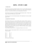
4.10
Character Generator ROM (CGROM)
.
NAR- 5650 Series User’s Manual
33
4.11
Sample Codes
/* *************************************
* EZIO RS232 LCD Control Sample Program
* *************************************
* *************************************************************************
* Company:
Portwell Inc.
* Date:
4/16/2003
* Program:
02A.c
* Version:
1.02
* Compile:
Linux GNU C
* Purpose:
Direct access to EZIO LCD, the program will display
*
messages according to the control button. The current
*
version only has the following function:
*
*
1: display welcome message
*
2: display UP message if "scroll up" button is pressed
*
3: display ENTER message if "ENTER" button is pressed
*
4: display ESC message if "ESC" button is pressed
*
5: display DOWN message if "scroll down" button is pressed
*
* Program Overview:
*
*
- Parameters:
*
fd
: a file name for open() method, here represents the com port
*
Cmd
: command prefix
*
cls
: clear command
*
init
: initialize command
*
blank
: display blank screen
*
stopsend
: stop input/output
*
home
: move cursor to initial position
*
readkey
: set to read from EZIO
*
hide
: hide cursor & display blanked characters
*
movel
: move cursor one character left
*
mover
: move cursor one character right
*
turn
: turn on blinking-block cursor
*
show
: turn on underline cursor
*
scl
: scroll cursor one character left
*
scr
: scroll cursor one character right
*
setdis
: set character-generator address
*
*
- Procedure:
*
1. The program sets up the environment, i.e. com port settings.
*
2. The main function MUST call init() twice to initialize EZIO
*
before any communication.
*
3. For executing any command, the command prefix, Cmd, MUST be
*
called be command. So all command contains two parts, eg.
*
to initialize the sequence of HEX number is 0xFE, 0x25.
*
4. After clear screen and display welcome message, ReadKey()
*
method must be call to advise EZIO for reading data.
*
5. A pooling method is implemented to get input from EZIO while
*
any button is pressed.
*
*
- NOTE: This program is a sample program provided " AS IS" with NO
*
warranty.
*
* Copyright (c) Portwell, Inc. All Rights Reserved.
*
* ************************************************************************/
#include <sys/stat.h>
#include <fcntl.h>
#include <unistd.h>
NAR- 5650 Series User’s Manual
34
#include <stdlib.h>
static int fd;
void SetEnvironment () {
system("stty ispeed 2400 < /dev/ttyS1");
system("stty raw < /dev/ttyS1");
}
int Cmd = 254; /* EZIO Command */
int cls = 1; /* Clear screen */
void Cls () {
write(fd,&Cmd,1);
write(fd,&cls,1);
}
int init = 0x28;
void Init () {
write(fd,&Cmd,1);
write(fd,&init,1);
}
int stopsend = 0x37;
void StopSend () {
write(fd,&Cmd,1);
write(fd,&init,1);
}
int home = 2 ; /* Home cursor */
void Home () {
write(fd,&Cmd,1);
write(fd,&home,1);
}
int readkey = 6
; /* Read key */
void ReadKey () {
write(fd,&Cmd,1);
write(fd,&readkey,1);
}
int blank = 8 ; /* Blank display */
void Blank () {
write(fd,&Cmd,1);
write(fd,&blank,1);
}
int hide = 12 ; /* Hide cursor & display blanked characters */
void Hide () {
write(fd,&Cmd,1);
write(fd,&hide,1);
}
int turn = 13 ; /* Turn On (blinking block cursor) */
void TurnOn () {
write(fd,&Cmd,1);
write(fd,&turn,1);
}
int show = 14 ; /* Show underline cursor */
void Show () {
write(fd,&Cmd,1);
write(fd,&show,1);
}
int movel = 16
; /* Move cursor 1 character left */
NAR- 5650 Series User’s Manual
35
void MoveL () {
write(fd,&Cmd,1);
write(fd,&movel,1);
}
int mover = 20
; /* Move cursor 1 character right */
void MoveR () {
write(fd,&Cmd,1);
write(fd,&mover,1);
}
int scl = 24;
/* Scroll cursor 1 character left */
void ScrollL(){
write(fd,&Cmd,1);
write(fd,&scl,1);
}
int scr = 28;
/* Scroll cursor 1 character right */
void ScrollR(){
write(fd,&Cmd,1);
write(fd,&scr,1);
}
int setdis = 64;/* Command */
void SetDis(){
write(fd,&Cmd,1);
write(fd,&setdis,1);
}
/* Add or Change Show Message here */
char mes1[] = "Portwell EZIO";
char mes2[] = "*************";
char mes3[] = "Up is selected";
char mes4[] = "Down is selected";
char mes5[] = "Enter is selected";
char mes6[] = "ESC is selected";
char nul[] = "
";
int a,b;
void ShowMessage (char *str1 , char *str2) {
a = strlen(str1);
b = 40 - a;
write(fd,str1,a);
write(fd,nul,b);
write(fd,str2,strlen(str2));
}
int main () {
SetEnvironment(); /* Set RAW mode */
fd = open("/dev/ttyS1" ,O_RDWR);/** Open Serial port (COM2) */
Init(); /* Initialize EZIO twice */
Init();
Cls(); /* Clear screen */
ShowMessage(mes1,mes2);
while (1) {
int res;
char buf[255];
NAR- 5650 Series User’s Manual
36
SetDis();
ReadKey(); /* sub-routine to send "read key" command */
res = read(fd,buf,255); /* read response from EZIO */
switch(buf[1]) {
/* Switch the Read command */
case 0xBE : /* Up Botton was received */
Cls();
ShowMessage(mes1,mes3); /** display "Portwell EZIO" */
break;
/** display "Up is selected */
case 0xBD : /** Down Botton was received */
Cls();
ShowMessage(mes1,mes4); /** display "Portwell EZIO" */
break;
/** display "Down is selected" */
case 0xBB : /** Enter Botton was received */
Cls();
ShowMessage(mes1,mes5); /** display "Portwell EZIO" */
break;
/** display "Enter is selected" */
case 0XB7 : /** Escape Botton was received */
Cls();
ShowMessage(mes1,mes6); /** display "Portwell EZIO" */
break;
/** display "Escape is selected */
}
}
}
NAR- 5650 Series User’s Manual
37