1
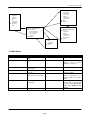
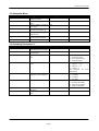
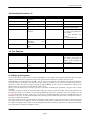
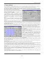
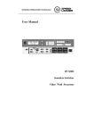
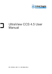
www.euvision.com
3xVision User guide
Rev.1.2 - 8/2/99
3xVision User Guide
Index
1. System Description
3
2. Keys functions
3
3. OSD Functions
3
3.1 Main Menu
4
3.2 Advanced Menu
5
3.3 Decoding Parameters /1
5
3.4 Decoding Parameters /2
6
3.5 Test Patterns
6
4. Setting up the system
6
5. Control Software
7
6. Technical chararcteristics
6.1 Input Signals
6.2 Output Signals
6.3 Controls
6.4 Functions
6.5 Shipping checklist
8
8
8
8
8
8
Euvision S.r.l. Via C. Zucchi, 15 – 00165 Rome – Italy – Tel. +39 06 6623564 Fax +39 06 66018467
Page 2
3xVision User Guide
1. System Description
The 3xVision kit consists of the splitter unit (1U 19” rackmount unit), 9 cables and a power cord.
On the front panel you can find, looking from the left to the right, the RS232 connector, three keys, two BNC (CVBS
input 1 and 2), a minidin connector (S-Video) and a 15 D – Sub connector, for RGB inputs.
On the back panel you will find the VDE connector with the power switch and two fuses (one per AC Phase), and the 9
output DB9 connectors.
Note that with RGB input no OSD functions are enabled and it’s not possible to choose it as default input on power up.
RGB
RS232
SVHS
Keys
CVBS1
CVBS2
(Front View)
Out 1
Out 9
(Rear View)
Power connector
and switch
2. Keys functions
The three multifunction keys on the front panel can be used to control all of the device’s parameters as well as to select
the video source. The three keys are used as Up, Enter and Down, so in every situation, the two peripheral button serve
to increase/decrease a parameter, while the center button is used to confirm the changes/select a parameter.
In normal mode, when there is no On Screen Display, the Up and Down keys, have two functions: if pressed briefly
they select the video source, which is indicated by the associated LED, while if pressed for about one second, the
magnification is changed between 1x1, 2x2 and 3x3.
Note that if the LED blinks regularly, it means that no video signal is detected, while if the LED is lit or blinks with a
very short off time, the video signal is properly detected; in the latter case, the blink simply notifies that the 75 ohm
termination has been switched off.
Pressing the Enter key recalls the On Screen Display, showing a menu with the most important image settings such as
color, contrast, brightness, hue etc.
In the On Screen Display mode, the Up and Down keys serve to choose the parameter to change then, pressing the
Enter key, the parameter is selected (the parameter changes color) and the Up and Down keys can be used to
increment/decrement the value.
Once the parameter is correctly set, you can confirm the change by simply pressing the Enter key again.
The only exception to this description is for the Y/N choices, for which the Enter key directly toggles between Yes and
No, without the need to use the Up and Down keys to change the parameter value and also without the need to deselect
the parameter by pressing the Enter key.
3. OSD Functions
Here follows a description of the menu tree as well as of the menu functions.
Euvision S.r.l. Via C. Zucchi, 15 – 00165 Rome – Italy – Tel. +39 06 6623564 Fax +39 06 66018467
Page 3
3xVision User Guide
Decoding Parameters
Comb Filter
White Peak.
Noise Filter
Aperture
Aperture BP
Chroma BW
è More
è Return
Main Menu
Brightness
Contrast
Saturation
Hue
Termination
Hor. Phase
è Advanced
Exit
Advanced Menu
è Decoding Parameters
è Test Patterns
Restore Defaults
Set As Initial Inp.
Start Up Mag
Sequence
è Return
Decoding Parameters
è More
VTR Mode
Prefilter
Chroma Trap
Colour Std.
Luma Delay
è Return
Test Patterns
Grid
Color Bars
Multiburst
è Return
3.1 Main Menu
Item
Brightness
Contrast
Saturation
Hue
Termination
Description
Value Range
Adjusts the brightness of the 0÷127
image
Adjust image contrast
-128÷127
Notes
Adjusts the color saturation 0÷127
of the image
Adjusts color phase, rotating 0÷255
the colors
Enables/Disables 75 Ohm Y/N
termination for active input
0 means b/w image
Hor. Phase
Shifts
the
horizontally
image -10÷10
è Advanced Menu
Enters the Advanced Menu
N/A
negative values generate an
image
with
inverted
luminance (negative)
this function is active also
for PAL signals
Disabling the termination
will be signalled by non
regular blink of the input’s
LED
Exceeding small values may
cause video to become dark
or oddly tinted; this doesn’t
cause any damage to the
device.
See section 3.2
Euvision S.r.l. Via C. Zucchi, 15 – 00165 Rome – Italy – Tel. +39 06 6623564 Fax +39 06 66018467
Page 4
3xVision User Guide
3.2 Advanced Menu
Item
è Decoding Parameters
è Test Patterns
Restore Defaults
Set as Initial Inp.
Start Up Mag
Sequence
è Return
Description
Enters
the
Decoding
Parameters Menu
Enters the Test Patterns
Menu
Restores factory presets for
active input
Sets the current input as the
one selected at power up.
Changes
the
splitter
Magnification
Enables
the
automatic
sequencing of the effects
Returns to the Main Menu
Value Range
N/A
Notes
See Section 3.3/3.4
N/A
See Section 3.5
N/A
N/A
x1, x2, x3
Y/N
N/A
3.3 Decoding Parameters /1
Item
Comb Filter
White Peak.
Noise Filter
Description
Enables/Disables the NTSC
Comb Filter/Pal Line Delay
Enables/Disables the White
Peaking Filter
Adjusts the Vertical Noise
Filter
Value Range
Y/N
Y/N
0÷3
Aperture
Sets Luminance Aperture 0÷3
Factor
Aperture BP
Sets Luminance Aperture 0÷3
Band Pass center frequency
Chroma BW
Sets the chroma Bandwidth
è More
Shows additional decoding N/A
parameters
Returns to the Advanced N/A
Menu
è Return
Notes
0÷3
0 – Normal Mode
1 – Searching mode
2 – Free running mode
3 – Filter Bypassed
0 – aperture = 0
1 – aperture = 0.25
2 – aperture = 0.5
3 – aperture =1
See diagrams for more
information
0 – 4.1 MHz
1 – 3.8 MHz
2 – 2.6 MHz
3 – 2.9 MHz
0 – small (620 KHz)
1 – nominal (800 KHz)
2 – Medium (920 KHz)
3 – Wide (1000 KHz)
See Section 3.4
See section 3.2
Euvision S.r.l. Via C. Zucchi, 15 – 00165 Rome – Italy – Tel. +39 06 6623564 Fax +39 06 66018467
Page 5
3xVision User Guide
3.4 Decoding Parameters /2
Item
è More
Description
Shows additional decoding
parameters
Enables/Disables
VTR
Mode
Enables/Disables Prefilter
Enables/Disables
chroma
trap
Sets the color standard
selections
VTR Mode
Prefilter
Chroma Trap
Color Std.
Value Range
N/A
Notes
See Section 3.3
Y/N
Used for noisy signals
Y/N
Y/N
Enhances transitions
Normally enabled, disabled
only for S-VHS signals
0 – PAL BGHI/NTSC M
1 – NTSC 4.43 (50Hz)/PAL
4.43 (60Hz)
2 – PAL N/NTSC 4.43
(60Hz)
3 – NTSC N/PAL M
0÷3
Adjusts the delay between -4÷3
Luminance
and
chrominance
Returns to the Advanced N/A
Menu
Luma Delay
è Return
See section 3.2
3.5 Test Patterns
Item
Grid
Description
Shows a grid pattern
Color Bars
Shows a color bars pattern N/A
(100%)
Shows multiburst pattern
N/A
Returns to the Advanced N/A
Menu
MultiBurst
è Return
Value Range
N/A
Notes
Pressing Enter clears the
test pattern and returns to
the menu; Pressing Up or
Down scrolls through the
test patterns.
Same as above
Same as above
See section 3.2
4. Setting up the system
To set up the system you first need to connect the RGBcables to the displays, following the numbering shown in figure
(output 1 connected to the top right cube of the wall viewed from the back) and, of course, the power cord.
The RGBcables are marked with “S” and “M” ; the “S” side can be connected to the Splitter (“M” side to the monitor).
Once the system is connected to the wall and an input signal is provided, you can turn on the system and proceed, if
necessary, to select the input, by simply pressing the Up and Down; the active input is recognized by looking at the
LEDs near the input connectors, which signal the active input.
When a signal is displayed on the screen, you have to proceed in adjusting the geometries, using the cube’s remote
controller.
Note that it’s possible to adjust the horizontal phase of the video signal by means of the Hor. Phase in the main menu of
the OSD; this setting is very useful to center the image before the setup of the geometries. This value usually has to be
set to 0, which makes the phase equal to the one present on common RGB inputs; note also that RGB inputs are not
adjustable in any way, so care should be taken when switching between RGB and other sources (composite, SVHS) is
expected, to match the geometries.
Once the geometries are set, you can adjust the parameters of the decoder; to get the best results we usually suggest to
have high contrast and low brightness values. Note that the input signal is conditioned by an AGC circuit, which limits
the settings of brightness and contrast: once the maximum contrast is reached, the white level is clamped and the black
level is lowered, overriding the brightness control.
Euvision S.r.l. Via C. Zucchi, 15 – 00165 Rome – Italy – Tel. +39 06 6623564 Fax +39 06 66018467
Page 6
3xVision User Guide
5. Control Software
The control software, supplied with the splitter, can be run from the diskette or from the hard disk; no installation is
needed since the program consists of only one file, so it’s possible to simply copy the file to the hard disk.
The functions are splitted in two pages, which can be selected by means of the tabs located in the top of the window;
one of the pages contains the parameters of the video input, while the second holds the splitter geometry parameters
along with the switches for some special functions.
To get started, the first thing to do is to set the serial port
which controls the splitter, using the radio button group
located at the right of the window.
Once the connection is established, it’s possible to set all
of the parameters by means of the sliders and check
buttons; note that the functions are the same described in
the OSD guide, so for further information on the specific
items please refer to chapter 3; note that all of this
parameters are not meaningful in the case of the RGB
input.
The Set as default input button, is used to set the current
input as the one selected at every subsequent splitter
power on.
Note that, since the data of the software and the one in the
splitter is not synchronized at the start of the program, it’s necessary to choose an input using the drop down list located
in the top right of the window; this will cause the software to update all of the data relative to the selected input, thus
synchronizing the parameters.
The splitter page shows a 3x3 cube system, on which is possible to select one or more cubes by simply clicking on it
with the mouse (to deselect a cube click the right one); selecting a (group of) cube(s) allows the arrow keys to shift the
image; thus compensating the settings of the cubes.
The arrow keys, repeated twice, allow to shift the image by
small (arrow near the cubes) or a large (arrow far from the
cubes) amount.
The magnification box allows the user to select the
magnification shown on the screen and thus to modify the
geometries of that magnification.
Checking one of the checkboxes in the colours group
allows to output a plain colour on a specific output; the
colour is selected by clicking on the colour sample, just on
the left of the colours checkboxes (Note that the feature is
available only on 1x1 magnification).
It’s however possible to automatically cycle the colours
using the colour wash function, but note that this function is
not stored in the splitter memory, so to enable it you will
require this software in any case (available on 1x1 and 2x2 magnifications).
The roll function allows to let the unit automatically shift the image from a side to the opposite, allowing the creation of
particular circular videowalls.
The interpolation function sets the 2 field optical interpolation, which is particularly needed when fast moving video is
fed to the device.
The freeze function makes the image still; it’s not possible to use this function along with roll.
The test patterns allow the system to generate test patterns without the need of an external generator and can be used
even if no video signal is fed to the splitter, except for the RGB input, which needs a reference synch.
Once the settings are finished, it’s possible to store the settings in the spliter, clicking on the store button; please note
that the storing is referred only to the selected input, so it’s necessary to repeat the storage operation for each input
separately.
Note also that Store sets the current magnification as the default one on power up; this means that the next time you
switch on the splitter you will have the last magnification set before the pressing of the store button.
Finally the load from disk and save to disk buttons allow to save the settings to disk, in order to save a copy of all the
setting for future uses.
To reset the settings to the default values it is possible to press the Restore Defaults button on the bottom right of the
window; this brings the software in it’s initial conditions.
Euvision S.r.l. Via C. Zucchi, 15 – 00165 Rome – Italy – Tel. +39 06 6623564 Fax +39 06 66018467
Page 7
3xVision User Guide
6. Technical chararcteristics
•
•
•
•
•
•
•
•
•
Resolution :
Analog Bandwidth:
Sampling Frequency:
Internal Sampled data format:
Pixel clock jitter (line to line):
Pixel clock jitter (cycle):
Power Consumption:
Weight:
Working temperature:
1024x576 (PAL)/1024x488 (NTSC)
~10 MHz
~20 MHz
linear 24 bit RGB (8:8:8)
<4 ns
<500 ps
~30W
5,6 Kg.
0-50 degrees Celsius
6.1 Input Signals
• 2 Composite inputs (with programmable 75 ohm termination)
• 1 S-VHS (Y/C) input (with programmable 75 ohm termination)]
• 1 RGBs input
6.2 Output Signals
• 9 x RGBs video to displays (DB9 female connectors)
6.3 Controls
• On Screen Display allows full control over all of the parameters of the device.
• 3 keys on the front panel to select video input/control OSD (this keys are remotable through an external mini
keyboard)
• RS232 port to remotely control the main parameters
•
•
•
•
6.4 Functions
On Screen Display to control all of the parameters
PAL/NTSC auto detection
Digital decoding of composite/S-VHS video
Programmable input selection at start up
Independent settings for each input
Regulations for decoded videos include Brightness,Contrast,Saturation,Hue, termination, Chroma Filter shape and
width, comb filter for NTSC/PAL Delay line, luma/chroma alignment for Composite video, noise filter
Internal test pattern generator
Analog persistence interpolation (to remove motion artifacts)
Interlaced/not interlaced input video auto detection
Inversion (negative) of the video input (only on composite/S-VHS inputs)
•
•
•
•
•
•
6.5 Shipping checklist
3xVision Main unit
AC Power cord
9x Output video cables (5 mt.)
Serial Cable (20 mt.)
Software diskette
User Manual
•
•
•
•
•
•
Euvision S.r.l. Via C. Zucchi, 15 – 00165 Rome – Italy – Tel. +39 06 6623564 Fax +39 06 66018467
Page 8