1
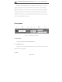
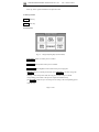
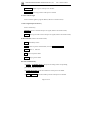
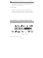
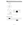
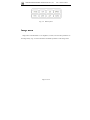
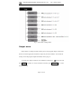
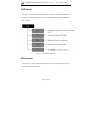
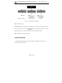
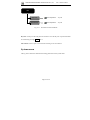
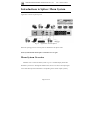
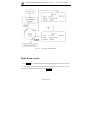
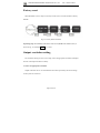
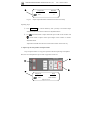
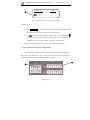
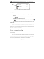
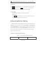
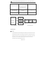
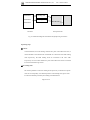
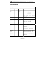
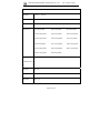
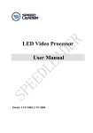
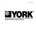
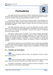
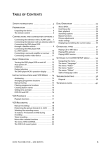
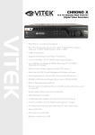
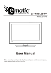
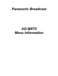
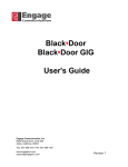
 SHENZHEN SPEEDLEADER TECHNOLOGY
User Manual
DVX802
Seamless Switcher
Video Wall Processor
SHENZHEN SPEEDLEADER TECHNOLOGY CO.,LTD.
LED Video Processor
About this manual
The manual must not be copied, reproduced or transcribed or translated
in whole or part, or disclosed commercially in any means (electronic,
mechanical, photocopying, recording or otherwise) or used for any
commercial profit without prior written consent of our company.
Please read this manual carefully before use. Any product specification
and information in the manual are only for reference and subject to
improvement without further notice. Unless otherwise specified, the
manual herein is acted as directions for use only and all statements,
information and the like do not constitute the warranty of any kind.
Trademarks
Both VGA and XGA are registered trademarks of IBM Company.
VESA is the trademark of Video Electronics Standards Association.
HDMI and High-Definition Multimedia Interface are the trademarks of
HDMI Licensing LLC.
Safety precautions
■ The equipment must be connected with ground wires.
■ Voltage with rated power shall be employed by the equipment and the
input voltage error shall be ±10%.
Page 1 of 50
SHENZHEN SPEEDLEADER TECHNOLOGY CO.,LTD.
LED Video Processor
■ Do not connect AC power cord with another AC power cord which
may cause excessive noise.
■ Do not use the equipment in the environment where the temperature is
-10℃ to 45℃ and the relative humidity is 90% or below.
■ Do not use the equipment in the special environment, such as near
heat source where the equipment may be overheated to damage. Please
use the equipment at the well-ventilated place and keep the air vent
smooth.
■ Do not expose the equipment at the place where the equipment may be
collided accidentally or vibrated and reinforce the equipment in case of
the vibration.
■ Do not put foreign objects such as water and metal objects into the
equipment. Otherwise, the equipment is damaged to cause a fire.
■ In case of any irregular or exceptional phenomenon, cut off the power
supply instantly, disconnect the AC power cord and remove troubles in
time as per "Troubleshooting".
■ Do not dismantle the equipment by yourself in case of any damage
and contact the designated maintenance center for repair.
Page 2 of 50
SHENZHEN SPEEDLEADER TECHNOLOGY CO.,LTD.
LED Video Processor
Attachments
Table 1: Packing List
Items
Name
Quantity
DVX802
1
Power cord
1
User manual
1
Certificate of conformity
1
Warranty card
1
*Above accessories may differ upon service condition of the user.
Page 3 of 50
SHENZHEN SPEEDLEADER TECHNOLOGY CO.,LTD.
LED Video Processor
Model descriptions
Table 2: Product Models
Models
Descriptions
DVX802
Basic model
DVX802S
SDI expansion port
DVX802D
DVI expansion port
DVX802V
VGA expansion port
DVX802C
VID (CVBS) expansion port
Page 4 of 50
SHENZHEN SPEEDLEADER TECHNOLOGY CO.,LTD.
LED Video Processor
Table of Contents
Overview ..............................................................................................7
Front Panel. ................................................................................................... 8
Rear Panel. ................................................................................................. 12
Introductions to Switcher Menu System. ..........................................13
Menu System Overview. ............................................................................. 14
Main Menu System...................................................................................... 15
Image Menu.. ............................................................................................... 16
Output Menu................................................................................................ 17
LED Menu ................................................................................................... 18
Effect Menu ................................................................................................. 18
Function Menu. ........................................................................................... 20
Logo Menu... ............................................................................................... 21
Advanced Menu .......................................................................................... 22
System Menu.... ........................................................................................... 23
Introductions to Splicer Menu System. ....................................................... 25
Menu System Overview. .....................................................................25
Main Menu System...................................................................................... 26
Image Menu... .............................................................................................. 27
Output Menu................................................................................................ 28
Splicing Menu. ............................................................................................ 28
Function Menu. ........................................................................................... 31
System Menu. .............................................................................................. 33
Basic Operation Instructions.. ...........................................................33
Factory Reset ............................................................................................... 34
Output Resolution Setting. .......................................................................... 34
Preset Storing and Recalling........................................................................ 38
Page 5 of 50
SHENZHEN SPEEDLEADER TECHNOLOGY CO.,LTD.
LED Video Processor
Setting and Application of Splicing............................................................. 39
Specifications.. .....................................................................................45
Troubleshooting.. ................................................................................48
Page 6 of 50
SHENZHEN SPEEDLEADER TECHNOLOGY CO.,LTD.
LED Video Processor
Overview
DVX802 is a combination of a seamless switcher and a video wall processor, which
supports 8-channel signal input, 3-channel signal output and a variety of extension
modules. In switcher mode, DVX802 can support separate output of preview signal,
program signal and LED screen signal and can realize dynamic seamless switching and
LOGO inserting among all channels (for detailed introductions and operations of the
switcher, please refer to page 6). At splicer mode, DVX802 supports 3-channel splicing
output and can realize the splicing function of three video processors without external
signal spliter (for detailed introductions and operations of the splicer, please refer to page
14). With high-performance picture processing and easiness and reliability in operation,
DVX802 is applied to the site movable stage and fixedly installed multifunctional video
processing equipment.
DVX802 can hold extensive input sources, is provided with a multichannel separate
image processing engine and can be accessed to video input up to eight channels,
including two DVI, two VGA, two VID, one HDMI and one extension input; and
meanwhile, each channel can receive the video signal with standard resolution or high
resolution or even the input with the high resolution up to 1920*1200@60Hz.
DVX802 can output 3-channel video. By virtue of rich terminal, more equipment can
be connected to DVX802. The output resolution of each channel can be determined by the
user and up to 2304*1152@60Hz or 1280*1920@60Hz resolution can be output to meet
various high-definition performances.
Page 7 of 50
SHENZHEN SPEEDLEADER TECHNOLOGY CO.,LTD.
LED Video Processor
DVX802 is more humanized in design, stronger in function and easy to use. Only
tapping your fingers on the front panel and menu system can finish complex settings.
Buttons and RS-232 are also can be used to realize the complete settings and operations.
Rich physical interfaces are provided to meet the requirements of the common output
equipment. And the rotary knob for adjusting relevant parameters of the picture quickly
also can be operated by the user easily…
Front panel
Fig. 1-1
Front Panel of DVX802
1. Power switch
"I": turn on the power; "O": turn off the power
2. State Display Screen
Display screen window displayed the state of the current machine, menu selection,
data state and other parameters.
3. Knob:
Page 8 of 50
SHENZHEN SPEEDLEADER TECHNOLOGY CO.,LTD.
LED Video Processor
Select up, down, right and left menus or adjust the value.
4. Menu operation
MENU -Menu key
ENTER -Enter key
5. FUNCTION
Fig. 1-2 Image Adjusting Keys (FUNCTION)
WIN SIZE -Adjust size of the preview window
WIN POS -Adjust position of the preview window
BRI/CONT -Adjust brightness and contrast of the preview/program
PRESET –Save or recall the preset mode; press PRESETkey to enter saving and
recalling
state of the preset mode; directly press numeric keys to load the
corresponding preset mode to the preview output and simultaneously
pressENTER+numeric keys to store the preview setting to the corresponding preset
mode directly.
Page 9 of 50
SHENZHEN SPEEDLEADER TECHNOLOGY CO.,LTD.
LED Video Processor
CROP SIZE -Adjust crop size of the preview window
CROP POS -Adjust crop position of the preview window
6. Source indicator light
Source indicator light for program channel (effective at switcher mode).
7. INPUT signal input selection key
Source selection key
FREEZE -Freeze or unfreeze the preview signal (effective at switcher mode)
LOGO -Take logo or black screen to the preview signal (effective at switcher mode)
8. TRANSITION (effective at switcher mode)
CUT –Immediately switch
TAKE-Switch as per the selected effect (use with FADE,PIP,TITLE
FADE –Fade- in Fade-out
PIP - Picture-in-picture effect
TITLE –Keying or title effect
Shortcut combination key
* ENTER + NUMERIC KEYS : Store preview settings to the corresponding
preset mode at the preset mode.
* ENTER+WIN SIZE: Reset the window size of the preview to default.
* ENTER+WIN POS: Reset the window position of the preview to default.
Page 10 of 50
SHENZHEN SPEEDLEADER TECHNOLOGY CO.,LTD.
LED Video Processor
* ENTER+CROP SIZE: Reset the crop size of the preview to default.
* ENTER+CROP SIZE: Reset the crop position of the preview to default.
* ENTER+BRI/CONT: Reset preview or program image quality to default.
* ENTER+INPUT: Program input selection
* ENTER+FREEZE: Freeze or unfreeze the current program signal.
* ENTER+LOGO: Switch logo or black screen to the current program signal.
* Press LOGO for a long time: Pop up LOGO selection mode of the program or preview
signal (at switcher mode).
*Press WIN SIZE circularly: Adjust the size of the preview window at a customized
proportion of 16:9/4:3/5:4/3:2/ at switcher mode and switch output channel at splicer
mode.
*Press CROP SIZE circularly: Adjust the crop size of preview at the input signal
proportion or customized proportion at switcher mode and switch output channel at splicer
mode.
*Press BRI/CONT circularly: Select picture parameters of the preview or program (at
switcher mode).
*Press WIN POS circularly: Switch output channel at splicer mode.
*Press CROP POS circularly: Switch output channel at splicer mode.
Page 11 of 50
SHENZHEN SPEEDLEADER TECHNOLOGY CO.,LTD.
LED Video Processor
Rear panel
Fig. 1-3
Rear Panel Connection Terminal of DVX802
1. Communication interface
RS-232 interface; with the adoption of a DB9 terminal, the interface is connected by
an RS232 or a console of the computer to control DVX802 completely.
2. Expansion interface
DVX802 can support one path of expansion input; the input modules for selection
are DVI/VGA/VID/3G-SDI.
3. Video input channel
DVX802 can receive two VGA, two DVI, one HDMI, two VID and one expansion
signal simultaneously.
4. Video output interface
Page 12 of 50
SHENZHEN SPEEDLEADER TECHNOLOGY CO.,LTD.
LED Video Processor
DVX802 supports three paths of separate video output: PREVIEW/OUTPUT1,
PROGRAM/OUTPUT2 and LED/OUTPUT3.
5. AC power interface
DVX802 provides a standard IEC power socket, with the input power being
100-240VAC, 50Hz/60Hz. Ground wires of the power supply must be grounded
reliably so as to avoid damage of the equipment or electric shock to the human body.
Introductions to Switcher Menu System
Application scenario 1 of seamless switcher
Fig. 2-1
Application 1 of Switcher
Application scenario 2 of seamless switcher
Page 13 of 50
SHENZHEN SPEEDLEADER TECHNOLOGY CO.,LTD.
LED Video Processor
Figure 2-2 Application 2 of Switcher
When DVX802 is used, the machine shall be set to the switcher mode:
Menu-System-Machine mode-Switcher-Confirm-Power on again
Menu System Overview
DVX802 owns a convenient menu system. Fig. 2-3 shows a default display menu after
the DVX802 is powered on. The user can observe the current preview signal source,
program signal source and other important information via the default menu.
Page 14 of 50
SHENZHEN SPEEDLEADER TECHNOLOGY CO.,LTD.
Fig. 2-3
LED Video Processor
Flowchart of System Menu
Main menu system
Press MENU key in default menu and then DVX802 enters the main menu system.
Fig. 2-4 is the first-level menus of the main menu system displayed on LCD and the user
can enter the next menus quickly by the rotary knob and ENTER key.
Page 15 of 50
SHENZHEN SPEEDLEADER TECHNOLOGY CO.,LTD.
Fig. 2-4
LED Video Processor
Menu System
Image menu
Image menu of the DVX802 is to set brightness, contrast, color and other parameters of
the image mainly. Fig. 2-5 shows submenus and settable parameters of the image menu.
Page 16 of 50
SHENZHEN SPEEDLEADER TECHNOLOGY CO.,LTD.
LED Video Processor
Fig. 2-5 Flowchart of Image Menu
Output menu
Output menu is to change resolution of the preview and program output. In this menu,
the user can select appropriate resolution to output as per actual condition. For resolutions
of the preview and program output of DVX802, refer to page 31.
To modify the output resolution, select different resolutions by
vertical knob and
press ENTER to confirm. To set the resolution accurately, press WIN SIZE key to enter
the shortcut menu.
Page 17 of 50
SHENZHEN SPEEDLEADER TECHNOLOGY CO.,LTD.
LED Video Processor
LED menu
DVX802 can adjust the image, output resolution, window, crop and other parameters of
the LED output channel separately. Fig. 2-6 shows the submenus and settable parameters
of the LED menu.
Fig. 2-6 Flowchart of LED Menu
Effect menu
Effect menu is to adjust switching effect between preview and program mainly. Fig. 2-7
shows the contents in effect menu.
Page 18 of 50
SHENZHEN SPEEDLEADER TECHNOLOGY CO.,LTD.
Fig. 2-7
LED Video Processor
Flowchart of Effect Menu
Preview Border-Preview border is a rectangular frame around edges of the image
when the user selects and edits the image on the preview display and is to remind the user
of the position and size of the current image. The user can turn on or off the border by the
knob as shown in Fig. 2-8.
Page 19 of 50
SHENZHEN SPEEDLEADER TECHNOLOGY CO.,LTD.
LED Video Processor
Preview frame
Fig. 2-8 Preview Frame
TITLE -Image matting (use with TITLE key in TRANSITION key area)
Select the preview signal source to be operated; at this moment, the preview signal source
can be edited; choose red, green and blue and determine a basic level from value 0 to value
15. The portions higher than the basic level in the signal are taken as the signals and those
lower than the basic level are filtered. Likewise, the greater value of the transparency
means higher transparency and the user can select the reversing mode as required; after
setting, press CUTor TAKEkey to add the preview signal to the program channel.
TITLE -Shortcut menu; press
TITLEkey again
CUTor TAKEkey till red light flashes and press
to enter TITLE menu directly.
Reset: Reset TITLE function to initial value.
Function menu
Page 20 of 50
SHENZHEN SPEEDLEADER TECHNOLOGY CO.,LTD.
Fig. 2-9
LED Video Processor
Flowchart of Function Menu
DVI EDID-Carry out EDID burn for each resolution of DVI input interface.
VGA setting-Automatically adjustment or manually adjust the position, clock and phase
parameter of each VGA input. The user can adjust the VGA picture in the menu when
finding the input VGA picture is biased.
Logo menu
Page 21 of 50
SHENZHEN SPEEDLEADER TECHNOLOGY CO.,LTD.
Fig. 2-10
LED Video Processor
Flowchart of Logo Menu
Select - Select the logo.
Capture and save – For capture source of the logo, select the logo storing position as per
to store. After the logo is stored, ☆ will be
preview picture of the user and enter
changed into ★ so as to indicate the user the current image data is stored.
Erase - Delete the logo stored by the user.
Advanced menu
Advanced function menu can be provided with key lock and fan control. Fig. 2-11
shows the contents in the menu.
Page 22 of 50
SHENZHEN SPEEDLEADER TECHNOLOGY CO.,LTD.
LED Video Processor
ADV Key lock Knob adjustment :on/off Fan control Knob adjustment :on/off Fig. 2-11
Flowchart of Advanced Menu
Key lock: All keys on the front panel are ineffective once the key lock is opened and shall
be unlocked by pressing ENTER for 3s.
Fan control: Select to open or close the fan according to site environment.
System menu
The Fig. below shows the submenus and setting parameters of the system menu:
Page 23 of 50
SHENZHEN SPEEDLEADER TECHNOLOGY CO.,LTD.
Fig. 2-12
LED Video Processor
Flowchart of System Menu
Language – Set the language of the whole menu system into Chinese or English.
Machine mode – The user can set the machine to the splicer or switcher mode as required.
System version –The user can check the software version and hardware version of the
equipment.
Factory reset – Restore all user parameters in the menu to factory settings.
Page 24 of 50
SHENZHEN SPEEDLEADER TECHNOLOGY CO.,LTD.
LED Video Processor
Introductions to Splicer Menu System
Application scenario of picture splicer
Fig. 3-1
Application of Picture Splicer
When the splicing processor is used, please set DVX802 to the splicer mode.
Menu-System-Machine mode-Splicer-Confirm-Power on again
Menu System Overview
DVX802 owns a convenient menu system. Fig. 3-2 is a default display menu after
DVX802 is powered on. Through the default menu, the user can observe the input signal
source and other important information corresponding to the current output cyclically.
Page 25 of 50
SHENZHEN SPEEDLEADER TECHNOLOGY CO.,LTD.
Fig. 3-2
LED Video Processor
Flowchart of System Menu
Main menu system
Press MENU key in default menu and then DVX802 enters the main menu system. Fig.
3-3 is the first-level menus of the main menu system displayed on LCD and the user can
enter the next menus quickly by the knob and ENTERkey.
Page 26 of 50
SHENZHEN SPEEDLEADER TECHNOLOGY CO.,LTD.
LED Video Processor
IMAGE
OUT
SPLICE
FUNC
ADV
SYSTEM
Fig. 3-3 First-level Submenus
Image menu
Image menu of the DVX802 is to set brightness, contrast, color and other parameters of
the image mainly. Fig. 3-4 shows submenus and settable parameters of the image menu.
Fig. 3-4 Flowchart of Image Menu
Page 27 of 50
SHENZHEN SPEEDLEADER TECHNOLOGY CO.,LTD.
LED Video Processor
Output menu
Output menu is to change resolution of the preview and program output. In this menu,
the user can select appropriate resolution to output as per actual condition. For resolutions
of the preview and program output of DVX802, refer to page 31.
To modify the output resolution, select different resolutions by
vertical knob and
press ENTER to confirm. To set the resolution accurately, press WIN SIZE key to enter
the shortcut menu.
Note: After the output resolution is modified, window size, window position, crop size and
crop position in the DVX802 splicer are recovered to the default. If the output resolution
stored in user preset is different from the current output resolution, the preset cannot be
called.
Splicing menu
Splicing menu is to set equal splicing and unequal splicing of the output and to splice a
complete picture through multiple output interfaces, in which each interface display one
part of the picture. The structural drawing of the splicing menu is as follows:
Page 28 of 50
SHENZHEN SPEEDLEADER TECHNOLOGY CO.,LTD.
Fig. 3-5
LED Video Processor
Flowchart of Splicing Menu
Splicing – Splicing can be classified into equal splicing and unequal splicing. When two
or more splicing areas on video wall have the same resolution, equal splicing is employed;
and unequal splicing is adopted when the resolutions are different; if there is no need to
splice, close the splicing menu.
Equal or unequal splicing shall be selected in the splicing menu. The parameter setting
menu has two output forms, in which one is the equal splicing parameters and the other is
the unequal splicing parameters.
Page 29 of 50
SHENZHEN SPEEDLEADER TECHNOLOGY CO.,LTD.
LED Video Processor
Equal splicing
Splice position: Display some part of the picture; calculation order for the
positions is from left to right and top to bottom as shown in Fig. 3-6:
Fig. 3-6
Order of Splicing Positions
H splice unit: Quantity for horizontal splicing, like 3 in splicing method 1*3 in Fig. 3-6.
V splice unit: Quantity for vertical splicing, like 1 in splicing method 1*3 in Fig. 3-6.
Unequal splicing
H Total Size: Total horizontal pixels of the spliced wall.
V Total Size: Total vertical pixels of the spliced wall.
H Splice Pos: Horizontal start pixel of the current output.
V Splice Pos: Vertical start pixel of the current output.
For splicing operation, the following sections will illustrate it explicitly.
Page 30 of 50
SHENZHEN SPEEDLEADER TECHNOLOGY CO.,LTD.
LED Video Processor
Function menu
Function menu is to burn EDID of different resolutions for DVI input interface and
make relevant settings for VGA channel. Fig. 3-7 shows the submenus in the function
menu:
Fig. 3-7
Flowchart of Function Menu
DVI EDID-Carry out EDID burn for each resolution of DVI input interface.
Page 31 of 50
SHENZHEN SPEEDLEADER TECHNOLOGY CO.,LTD.
LED Video Processor
VGA set up-Automatically adjust or manually adjust the position, clock and phase
parameter of each VGA input. The user can adjust the VGA picture in the
menu when finding the input VGA picture is biased.
Fig. 3-8
Flowchart of Advanced Menu
Genlock Type: Choose free run or V Lock as required, in which the free run is the
setting when single DVX802 is used for splicing; and when multiple DVX802 are
spliced, the synchronization mode of each equipment shall be set into the V Lock
mode Genlock.
Key lock: All keys on the front panel are ineffective once the key lock is opened and
shall be unlocked by pressing ENTER for 3s.
Fan control: Open or close the fan.
Page 32 of 50
SHENZHEN SPEEDLEADER TECHNOLOGY CO.,LTD.
LED Video Processor
System menu
The Fig. 3-9 shows the submenus and setting parameters of the system menu:
Fig. 3-9
Flowchart of System Menu
Language – Set the language of the whole menu system into Chinese or English.
Machine mode – The user can set the machine to the splicer or switcher mode as required.
System version –The user can check the software version and hardware version of the
equipment.
Factory reset – Restore all user parameters in the menu to factory settings.
Basic Operation Instructions
The followings detail the common functions of DVX802 such as factory reset, output
resolution setting, input source selection, switching, output window operation, brightness
and contrast adjustment as well as preset saving and recalling, etc.
Page 33 of 50
SHENZHEN SPEEDLEADER TECHNOLOGY CO.,LTD.
LED Video Processor
Factory reset
When DVX802 is used, it may be necessary for the user to reset the machine to factory
defaults.
Fig. 4-1 Factory Reset Flowchart
Operating steps: Enter factory reset menu of the menu system at the default menu (as
shown in Fig. 4-1) and tap ENTERkey to reset.
Output resolution setting
The resolution setting involves in two steps, choose an appropriate resolution and adjust
the size of the output window accurately.
1. Choose an appropriate resolution
Output resolutions for #1-#3 of DVX802 are the same. Specifically, the menu settings
of the system are as follows:
Page 34 of 50
SHENZHEN SPEEDLEADER TECHNOLOGY CO.,LTD.
Fig. 4-2
LED Video Processor
Flowchart for Modifying Output Resolution
Operating steps: Enter output menu of the menu system at the default menu (as shown in
Fig. 4-2), choose the appropriate resolution and tap
key to confirm.
2. Adjust the size and position of the output window accurately
According to different output windows of each interface, #1-#3 output of DVX802
can be modified individually via keys.
① ② ④ ③ Output #1 Window H Size: 960 Page 35 of 50
SHENZHEN SPEEDLEADER TECHNOLOGY CO.,LTD.
LED Video Processor
⑤ Output #1 Window H Pos: 0 Fig. 4-3
Adjust Output Resolution and Window Position Accurately
Operating steps:
① Press WIN SIZE key in FUNCTION key area cyclically to switch the output
channel till LCD screen enters window size adjustment menu.
② Use
horizontal knob to adjust horizontal pixel width of the window and
vertical knob to adjust vertical pixel height of the window in window
adjustment menu.
Adjust the horizontal start and vertical start of the window in the same way.
3. Adjust crop size and position of output window
Crop of output window is to crop part of pictures after the input image is amplified.
Here, the user can adjust the crop size and crop position as follows:
② ① ④ Output #1 Crop H Size: 1024<100%> Page 36 of 50
③ SHENZHEN SPEEDLEADER TECHNOLOGY CO.,LTD.
LED Video Processor
Output #1 Crop ⑤ H Pos: 0 Fig. 4-4 Adjustment of crop size and crop position
Operating steps:
① Press CROP SIZE key in FUNCTION key area cyclically to switch the output
channel till LCD screen enters window size adjustment menu.
② Use
horizontal knob to adjust horizontal width of the window and
vertical knob to adjust vertical height of the window in crop adjustment menu;
and meanwhile, LCD screen will display percentage of enlargement.
Adjust the horizontal start and vertical start of the window in the same way.
4. Adjust brightness and contrast of output window
Considering actual conditions of the site, the user is likely to adjust the brightness
and contrast of the image. In view of this, the brightness and contrast of all signal sources
of the DVX802 splicer can be adjusted individually as follows:
① ② Page 37 of 50
SHENZHEN SPEEDLEADER TECHNOLOGY CO.,LTD.
③ Input VGA1
Fig. 4-5
Image
Brightness:
Contrast:
LED Video Processor
64
64
Flowchart for Adjusting Brightness and Contrast
Operating steps:
① Press 2-5 and 7-0 keys in INPUT key area, in which the pressed keys will turn
into orange.
② Press
key in FUNCTION key area; now, the LCD screen enters
the brightness and contrast adjusting menu.
③ Use
horizontal knob to adjust the brightness of the window and
vertical knob to adjust the contrast of the window in window adjustment menu
5. Select input
DVX802 is provided with up to eight channels of signal input. Numbers 2-5, 7-0 in
the INPUT key area are corresponding to the INPUT interfaces. Tapping corresponding
key directly can select the current channel.
Preset saving and recalling
1. Preset saving
Preset saving is realized by tapping combination key directly. The saved preset data
include the input source of all current channels, size and position of the output image as
well as splicing state, etc. Specifically, the preset data are saved as follows:
Page 38 of 50
SHENZHEN SPEEDLEADER TECHNOLOGY CO.,LTD.
LED Video Processor
Operating steps:
Press PRESET key at the default menu; now, all keys in INPUT key area turn on; and
press ENTERkey + numeric keys in INPUT key area to store; ☆ on the LED display
screen corresponding to the saved preset number will be filled like ★.
2. Preset recalling
Preset recalling is realized by keys on the front panel directly.
Operating steps:
Press PRESET key at the default menu; now, all keys in INPUT key area turn on;
select ★ 0-9 in the INPUT key area to take the preset.
Setting and Application of Splicing
DVX802 has simple and practical splicing function which can be realized only by the
splicing menu. The splicing can be classified into equal splicing and unequal splicing, in
which the equal splicing refers to the horizontal pixels and vertical pixels of each part of
the spliced video wall are equal, whilst the unequal splicing refers to the pixels of each
part of the video wall may be unequal. Here, we will focus on the equal splicing and
unequal splicing of LED video wall.
·Example of 1*3 equal splicing of LED video wall
Table 4-1
Equipment name/model
Current Equipment and Relevant Parameters
Function/parameter
Page 39 of 50
Quantity
SHENZHEN SPEEDLEADER TECHNOLOGY CO.,LTD.
LED Video Processor
Three 1270*896 LED video
LED video wall
walls are spliced into the
3
3810*896 LED video wall
in the manner of 1*3.
LED sending card
DVX802
Support 1280*1024 at
Video splicer
OUTPUT#1 Sending card
OUTPUT#2 Sending card
OUTPUT#3 Sending card
3
maximum.
DVX802
1
1 2 3 1*3 LED spliced wall
Operating steps:
① Connect
Connect DVX802, three LED sending cards and three parts of the LED video wall,
in which the three channels of DVI output for DVX802 are connected to the LED
sending cards respectively, the LED sending cards are connected to the video walls
respectively via CAT5 cables and the three parts of the LED video wall are
connected to form an individual single screen.
Page 40 of 50
SHENZHEN SPEEDLEADER TECHNOLOGY CO.,LTD.
LED Video Processor
②Set sending cards
Set relevant parameters of the three sending cards respectively so that the three
video walls can work separately. For detailed operation of the sending cards, please
refer to instruction manual provided by the sending card manufacturer.
③
Set output resolution
Select the output resolution of the DVX802 to 1280*1024 and press WIN SIZE key
in the FUNCTION key area to adjust the resolution of the OUTPUT #1-#3 to
1270*896.
④
Select signal source
Select signal sources of the DVX802 and choose the same input source for the 3
output channels.
⑤Set splicing menu of DVX802
Output
#1
Output
#2
Splice:
Equal
Splice:
Equal
H splice unit: 3
H splice unit: 3
V splice unit:
1
V splice unit:
1
Splice pos:
1
Splice pos:
2
Page 41 of 50
SHENZHEN SPEEDLEADER TECHNOLOGY CO.,LTD.
Output
#3
Splice :
Equal
LED Video Processor
H splice unit: 3
V splice unit:
1
Splice pos:
3
Note: Upon different output connections, splice position in the splicing setting also
shall be changed correspondingly.
·Example of unequal splicing of LED video wall
Table 4-2
Equipment name/model
Current Equipment and Relevant Parameters
Function/parameter
Quantity
Screen 1: 1152*1024
Screen 2: 960*1024
LED video wall
2
Total horizontal pixels: 2112
Total vertical pixels: 1024
LED sending card
Support 1280*1024 at maximum.
2
DVX802
Video splicer
1
Page 42 of 50
SHENZHEN SPEEDLEADER TECHNOLOGY CO.,LTD.
LED Video Processor
OUTPUT#1 OUTPUT#2 Sending card 1 2 Sending card OUTPUT#3 DVX802
LED spliced wall
Fig. 4-7 Schematic Diagram of DVX802 Unequal Splicing Connection
Operating steps:
①Connect
Connect DVX802, two LED sending cards and two parts of the LED video wall, in
which OUTPUT#1 and OUTPUT#2 of DVX802 are connected to the LED sending
cards respectively, the LED sending cards are connected to the video walls
respectively via CAT5 cables and the two parts of the LED video wall are connected
to form an individual single screen.
②Set sending cards
Set relevant parameters of the two sending cards respectively so that the two spliced
walls can work separately. For detailed operation of the sending cards, please refer
to instruction manual provided by the sending card manufacturer.
Page 43 of 50
③
SHENZHEN SPEEDLEADER TECHNOLOGY CO.,LTD.
LED Video Processor
Set output resolution
Select the output resolution of the DVX802 to 1280*1024 and press WIN SIZE key
in the FUNCTION key area to adjust the resolution of the OUTPUT #1 to
1152*1024 and OUTPUT #2 to 960*1024.
④Select signal source
Select input sources of the DVX802 and choose the same input source for the
OUTPUT#1 and OUTPUT#2.
⑤Set splicing menu of DVX802
Output
Splice:
#1
Output
Unequal
#2
Splicing:
H Total Size: 2112
H Total Size: 2112
V Total Size: 1024
V Total Size: 1024
H Splice Pos: 0
H Splice Pos:1152
V Splice Pos: 0
V Splice Pos: 0
Unequal
Note: Upon different output splicing connections, start position in the splicing setting also
shall be changed correspondingly.
Page 44 of 50
SHENZHEN SPEEDLEADER TECHNOLOGY CO.,LTD.
LED Video Processor
Specifications
Video input
Interface
Quantity
Connector
DVI
2
DVI-D
Specifications
DVI1.0
HDMI1.3
downward
compatibility
VESA
standard, PC
to
1920*1200
HD to 1080P
VGA
2
DB15
VESA standard PC to 1920*1200
VIDEO
2
BNC
PAL/NTSC/SECAM 1Vpp±3DB(0.7V
Video+0.3v
Sync)75ohm
480i,576i
HDMI
1
HDMI
DVI1.0
HDMI1.3 downward
compatibility
PC to 1920x1200
Expansion
1
BNC/VGA/DVI
HD to 1080p
3G-SDI Supported resolution: 1080p
input
60/50/30/25/24, 1080i 60/50, 720p
(optional)
60/50,625/525 line, support signals
looping out
Page 45 of 50
SHENZHEN SPEEDLEADER TECHNOLOGY CO.,LTD.
LED Video Processor
(PREVIEW/OUTPUT 1)/(POGRAM/OUTPUT 2)
Quantity
VGA x1、DVI x1
Connector
DB15, DVI-D
Standard
VESA standard
Resolution
640*480@60Hz
1280*720@50Hz
800*600@60Hz
1920*1080@50Hz
1024*768@60Hz
1280*1024@60Hz
1280*1920@60Hz
1920*1080@60Hz
1366*768@60Hz
1440*900@60Hz
1536*1536@60Hz
1680*1050@60Hz
1920*1200@60Hz
1920*1280@60Hz
2048*1152@60Hz
2304*1152@60Hz
2560*960@60Hz
LED/OUTPUT
3
Quantity
DVI x2
Connector
DVI-D
Standard
DVI 1.0
Page 46 of 50
SHENZHEN SPEEDLEADER TECHNOLOGY CO.,LTD.
Resolution
640*480@60Hz
1280*720@50Hz
800*600@60Hz
1920*1080@50Hz
1024*768@60Hz
1280*1024@60Hz
1280*1920@60Hz
1920*1080@60Hz
1366*768@60Hz
1440*900@60Hz
1536*1536@60Hz
1680*1050@60Hz
1920*1200@60Hz
1920*1280@60Hz
2048*1152@60Hz
2304*1152@60Hz
2560*960@60Hz
GENERAL
Weight
4.7kg
Dimension
6.5cm (height)*44cm (width)*32cm (depth)
Power supply
100VAC-240VAC 50/60Hz
Power
40W
consumption
Working
LED Video Processor
0-45℃
temperature
Page 47 of 50
SHENZHEN SPEEDLEADER TECHNOLOGY CO.,LTD.
LED Video Processor
Troubleshooting
Problems may be encountered during installation or use. Here, the user can follow
the steps below to remove the troubles; if the steps below still cannot fix the problems for
you, please contact the local dealer.
1. The equipment has no image and the indicator light doesn’t work.
Check whether the power supply is connected well and the power switch is turned
on.
2. LCD screen on the key panel has data displayed, but no image output.
Check whether the signal is connected correctly.
Check whether the equipment supports the resolution and refresh the frequency.
Reset the equipment to factory default settings.
3. VGA picture cannot be displayed on the full screen or is deflected.
Check whether VGA wire is up to standard or overlong.
Open the menu: System→VGA settings→Automatic adjustment; and hit VGA
automatic adjustment.
Adjust the picture manually in VGA settings.
Page 48 of 50
SHENZHEN SPEEDLEADER TECHNOLOGY CO.,LTD.
LED Video Processor
4. HDMI/DVI output picture cannot be displayed on the full screen.
Reset output resolution of the equipment.
Check whether output resolution of PC or notebook is identical to the resolution
received by the splicer.
Check whether desktop wallpaper is too small.
Page 49 of 50
SHENZHEN SPEEDLEADER TECHNOLOGY CO.,LTD.
LED Video Processor
Industry Sales and Service Hotline: 400-6286-959
SHENZHEN SPEEDLEADER TECHNOLOGY CO.,LTD.
Tel: 0755-26588939
Fax: 0755-26586619
Post Code: 518052
Address: 6/F, Bldg. 78, Majialong Industrial Zone, Nanshan District, Shenzhen
http://www.speedleader.cn
Page 50 of 50