1
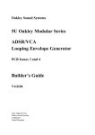
Oakley Sound Systems
5U Oakley Modular Series
Sample/Slew
PCB issue 5
User Manual
V5.1.1
Tony Allgood
Oakley Sound Systems
CARLISLE
United Kingdom
The front panel of the MOTM format Sample/Slew module.
2
Introduction
This is the User Manual for the Sample/Slew 5U module from Oakley Sound. This document
contains an overview of the operation of the unit and the calibration procedure
For the Builder's Guide, which contains a basic introduction to the board, a full parts list for
the components needed to populate the board or boards, and a list of the various
interconnections, please visit the main project webpage at:
http://www.oakleysound.com/sample.htm
For general information regarding where to get parts and suggested part numbers please see
our useful Parts Guide at the project webpage or http://www.oakleysound.com/parts.pdf.
For general information on how to build our modules, including circuit board population,
mounting front panel components and making up board interconnects please see our generic
Construction Guide at the project webpage or http://www.oakleysound.com/construct.pdf.
The issue 5 Oakley Sample/Slew module behind a natural finish MOTM format Schaeffer panel.
3
The 5U Sample/Slew Module
This compact single width module features a powerful sample and hold module with
controllable correlation, a slew generator, a wide range clock oscillator and a dual output
noise generator. It can be used to generate random and pseudo random control voltages,
staircase waveforms, deliberate aliasing of audio signals and many other uses.
The Oakley sample/slew module has two modes of operation selected by a switch on the front
panel.
The first is the 'hold' mode. This mode is the traditional sample and hold (S/H). It has a signal
input, a signal output and a clock input. The module's job is to memorise the input voltage and
present that to the output socket on command of the rising edge of a clock signal. The clock
signal is any signal input you like, but it is traditional to use a gate type pulse. If a signal is
inserted into the clock input, when the signal rises over 1V or so, the command is given to
hold. The hold output will then remain fixed no matter what the input signal is now doing.
That is until the command to hold is given again whereby it attains a new output value.
The second mode is 'track'. This functions like the so-called 'sample and hold' module on the
Korg MS-20. With a clock input above 1V then the output of the module will follow in the
input signal. When the clock input falls below 1V the output will then be held and not change
again until the clock input rises again above 1V.
The restriction pot affects the way the hold output changes with respect to the current input
level and previously held output level. With the pot fully off the unit behaves just like any
other S/H, but at full, the output is restricted to move by only a small amount after each new
sample. The output will still have the same range as the input, but will need more hold
commands to get there.
In reality the hold function is not perfect in either mode. The module uses an analogue
memory module and as such the stored voltage will slowly change over time. We typically call
this change' droop' because the voltage tends to be drawn down to zero. The droop is
relatively small and for most synthesiser patches it is not a problem.
The module features an inbuilt clock generator. This essentially is a wide range VCO (from
about one cycle per minute to around 2kHz) which can be used to directly control the S/H
module when no jack is inserted into the clock in socket. The output of the oscillator is
available as a +/-5V square wave at the clock out socket.
The slew generator can be accessed separately from the S/H section, but its input is
normalised to the output of the S/H when there is no jack plug inserted into the slew input
socket. The slew generator smooths any sudden changes in the input signal. Thus a square
wave becomes more like a triangle, and keyboard CVs start sliding between notes.
A noise source is available from the noise out socket. The noise could be described as white
with a gentle roll off above 6kHz. This analogue random voltage source can used in
conjunction with the S/H to produce the classic sample/hold patterns heard in numerous
recordings. The clipped out socket is an alternative noise source. This features the same white
4
noise signal but soft clipped to +/-5V. This signal is less random as the noise signal swings
between defined levels, but it is ideal when used with the S/H as it creates a more predictable
output.
The CLK LED lights when the clock input is above 1V.
The module accommodates either our standard Oakley/MOTM power header or a
Synthesizers.com power header.
5
Front panel controls
CLOCK RATE
As of issue 5 the Oakley Sample/Slew module contains an internal clock generator. The clock
generator is a simple oscillator that spans from around one cycle per minute to around 2kHz.
The output is automatically routed to the clock input of the sample/hold circuit when no jack
is inserted into the clock input socket.
The output of the clock generator is available as a pulse waveform from the clock output
socket. The waveform is a square wave except at frequencies below 20Hz where is becomes
increasingly a narrower pulse. The trimmer CLK on the printed circuit board sets the minimum
frequency.
CLK
The LED lights when the clock input goes above 1V. Since the clock input is normalised to
the output of the clock generator the LED will normally flash in sync with the internal clock
frequency.
RESTRICTION
In the Oakley Sample/Slew module there are two analogue memory units connected in
cascade or series. The second one is designed to hold the previously held value of the first
memory unit. The output of the module is derived from the first memory unit. However, the
input to the first memory unit comes from a mix of the voltage on the sample input socket and
the output of the second memory unit. The degree of mixing is determined by the restriction
pot. With the pot fully counter clockwise, the input to the memory unit is derived solely from
the input socket. With the pot fully clockwise, the input to the memory unit comes mostly
from the second memory unit.
This means that with the restriction pot fully clockwise the voltage that will be loaded into the
memory unit cascade is going to be somewhere between the voltage now seen on the input
socket and the voltage on the output socket. Thus the output now changes towards the new
input voltage but not instantly to it. This is excellent for generating stair step progressions
from input signal that change very quickly.
TRACK/HOLD
This is the mode switch and allow the sample/hold memory units to be used either in
traditional sample and hold, or track and hold modes.
SLEW
This pot controls the time constant of the slew or lag generator. The slew generator is
essentially a one pole low pass filter. However, rather than dealing with audio signals it is
specialised in dealing with control voltages. It is designed to slow down any rapid changes in
the input signal. The most common application of this in a synthesiser is that of glide or
6
portamento, whereby the keyboard CV is not allowed to quickly transition between one note
and the next but to slowly glide up or down. The shape of the output from this slew generator
is often described as being exponential, in other words, it moves faster at first and then slows
down before arriving at its target destination. Slew controls the overall rate of the transition
with the fastest speeds found when the pot is fully counter clockwise.
The slew input socket is normalised to the output of the sample/hold module. Thus the slew
generator can used to remove the sharp steps created by the sample/hold function.
7
Power supply requirements
The design requires plus and minus 15V supplies. The power supply should be adequately
regulated. The current consumption with no output signal is about +44mA for the +15V rail
and -34mA for the -15V rail. Power is routed onto the PCB by a four way 0.156” MTA156
type connector or the special five way Synthesizers.com MTA100 header.
Power connections – MOTM and Oakley
The PSU power socket is 0.156” MTA 4-way header. This system is compatible with MOTM.
Power
Pin number
+15V
Module GND
Earth/PAN
-15V
1
2
3
4
The earth/pan connection has been provided to allow the ground tags of the jack sockets to be
connected to the powers supply ground without using the module’s 0V supply. Earth loops
cannot occur through patch leads this way, although screening is maintained. Of course, this
can only work if all your modules follow this principle.
Power connections – Synthesizers.com
The PWR power socket is to be fitted if you are using the module with a Synthesizers.com
system. In this case the PSU header is not fitted. The PWR header is a six way 0.1” MTA, but
with the pin that is in location 2 removed. In this way location 3 is actually pin 2 on my
schematic, location 4 is actually pin 3 and so on.
Power
Location number
Schematic Pin number
+15V
Missing Pin
+5V
Module GND
-15V
Not connected
1
2
3
4
5
6
1
2
3
4
5
+5V is not used on this module, so location 3 (pin 2) is not actually connected to anything on
the PCB.
If the PSU header is fitted then pins 2 and 3 of PWR are linked together. This connects the
panel ground with the module ground.
8
Calibration
You can use a simple fine bladed screwdriver for adjusting the module.
You should make sure your modular has been powered up for at least ten minutes prior to
calibration. Also, it is a good idea to have the room temperature close to what it would
normally be when playing your modular.
NOISE
This trimmer sets the level of the analogue noise source. Since noise is a random voltage is not
that easy to set this exactly. However, you are looking to set this so that it gives you a signal
of roughly equivalent volume to a 5V peak sine wave. That is, the noise output should sound
as loud as a sine wave from your VCO. You can compare the outputs on a suitable voltmeter
or level meter on a mixer or DAW. If using a scope, then adjust NOISE until the peak noise
output level is roughly +/-6V.
If you can't get the signal loud enough then try lowering the value of R31.
CLK
Set the rate pot to the slowest setting and adjust CLK so that the CLK LED flashes at its
fastest rate. Now turn CLK the completely opposite way to ensure that the oscillator is
moving at its slowest. You may find the LED remains lit. Monitor the voltage at pin 8 of U3
and it should be around -3V. Very slowly back off CLK until you notice the voltage rise to
around -2V. The oscillator should now be oscillating, albeit very slowly. Check that the rate
pot does what it should.
9
Final Comments
I hope you enjoy using the Oakley Sample/Slew
If you have any problems with the module, an excellent source of support is the Oakley Sound
Forum at Muffwiggler.com. Paul Darlow and I are on this group, as well as many other users
and builders of Oakley modules.
If you have a comment about this user manual, or have a found a mistake in it, then please do
let me know.
Last but not least, can I say a big thank you to all of you who helped and inspired me. Thanks
especially to all those nice people on the Synth-diy and Analogue Heaven mailing lists and to
those at Muffwiggler.com forum.
Tony Allgood at Oakley Sound
Cumbria, UK
© June 2014 – updated August 2014
No part of this document may be copied by whatever means without my permission.
10