1
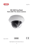
MINI MEDIAM SPEED DOME CAMERA
User Manual
Power Supply DC 12V
Factory Configuration: PELCO-D protocol, Baud rate 2400, Address code 1
※Please read carefully before using this manual
Catalogue
Chapter 1 Product Summarize………..………….…………….………….………….………….………….……………2
1 . 1 Te c h n i c a l P a r a m e t e r s … … … … … … . … … … … . … … … … … . … … … … . … … … … . … … … … . … … … … . … … … … … . 2
1.2 Function description………………………………………………….………….………….………….……….……….3
C h a p t e r 2 E q u i p m e n t i n s ta l l a t i o n … … … … … . … … . … … … … … … … … . … … … … . … … … … . … … … … . … . . … … … … 6
2.1 DIP sw itch settings………………......................................... ……….………….………….………….….................6
2.2 Dome camera structure diagram…………………..…..……………………….………….………….………….……8
2 . 3 B r a c k e t i n s ta l l a t i o n d i a g r a m . . . … … . . … … … … … . … … . . … … … … … … … … . … … … … . … … … … . … … … … . … … . . . 9
Chapter 3 System OSD menu settings....…………………………………….………….………….………….………10
3.1 Pow er-on self-test………….……………………………………………….………….………….………….………….10
3.2 Preset point setting and calling……………………………………….………….………….………….…………….10
3 . 2 . 1 S e t p r e s e t p o i n ts … … … … . … … … … … … … … … … … . . … … … … … . … … … … . … … … … . … … … … . … … … … … . 1 0
3 . 2 . 2 C a l l p r e s e t p o i n ts … … . … … … … … … … … … … … … … … . … … … … . … … … … . … … … … . … … … … . … … … … … . 1 0
3 . 3 P r e s e t p o i n t f u n c t i o n ta b l e . … … … … … … … … … … … … … … … … … . … … … … . … … … … . … … … … . … … … … … . 1 0
3 . 4 < M A I N M E N U > … … … … . … … … … … … … … … … … … . . … … … … … . … … … … . … … … … . … … … … . … … … … … … . 11
3.5 <CAMERA >(Lens) settings menu.................................. ……….………….………….………….….....................11
C h a p t e r 4 S i m p l e Tro u b l e sh o o t i n g a n d M ai n t e n an c e …… … … … …. … … … … . …… … … . ……… … . … ……… . …. 1 2
4 . 1 S i m p l e Tr o u b l e s h o o t i n g Ta b l e … … … … … … … … . . … … … … … … … . … … … … . … … … … . … … … … . … … . . … … … 1 2
4.2 After Ser vice ………………………………………………….………….………….………….………….……...……..14
1
Chapter 1 Product Summarize
1.1 Technical Parameters (standard)
Model number
4 INCH MINI MEDIAM SPEED DOME CAMERA
Optical focus
10X
Image sensor
1/3"CCD
Signal mode
PAL / NTSC
Resolution
Optical focus
Presets
12X
480TVL / 540TVL / 600TVL/650TVL/
650TVL/ 700TVL 700TVL
Manual/Auto, adapt high performance DSP to realize full digital high continuous
focusing function.
256
Cruise scan
30 presets can join cruise
Other scan
Support Horizontal scan
Rotation range
Horizontal 360°unlimted rotation, Vertical 90°, auto reversal
Rotation speed
Horizontal & Vertical Min 0.01° Max 60°/s.
Communications
OSD
Temperature control
system
Power supply
Ball cover dimension
PELCO-D and PELCO-P
Input 95 on the keyboard to call the module menu
Optional
DC12V 2A
4 inch optical glass cover
2
Material
Work
environment
Aluminum shell, waterproof IP66
-20℃~+50℃(select temperature control accessories), <95%RH
1.2 Function description
1. Set address coding, baud rate, control protocol
Any operation commands the camera has its own objectives address coding, baud rate, control protocol, a single
camera only to respond with its own address coding, baud rate, control agreement under the operation of the
command. Camera address coding, baud rate, control protocol specific settings please refer to the DIP settings.
2. Target tracking
Users can use the controls on the keyboard joystick control of the upper and lower turning left and right cameras
can be used to track moving targets or moving horizon, while the focal length can be adjusted to change the
perspective of the size or the target image size. In the auto-focus of the state, with the lens rotation, the camera will
automatically adjust according to a rapid scene changes, instantly get a clear picture.
3. Focal length / speed automatic matching technique
Manual adjustment, the longer the focal length of the case, a reflection of high-speed ball machine makes a slight
touch screen joystick may move back, resulting in data loss. Based on user-friendly design, ball according
to the proximity of the foca l length of the camera automatically adjusts the horizontal and vertical speed,so that
manual operation is more simple and easy to track targets.
4. Set and call preset position
Preset function is the current state of the ball under the PTZ function of the horizontal angle, tilt angle and camera
lens focal length, etc. position parameters stored in memory, you need to call these parameters can be quickly and
PTZ cameras will be adjusted to that location. The operator can quickly and easily by controlling the keyboard,
3
infrared controller, control equipment such as storage and call the preset point, the ball machine to support 256
preset points.
5. Lens Control
(1) Zoom control
Users can control the keyboard or through the ball machine to adjust the focus of the distance matrix of the host,
receive the necessary panoramic images, or is a fine view.
(2) Focus Control
System default auto-focus, zoom, the camera lens will be the center of the screen features auto-focus, to maintain a
clear picture; in exceptional circumstances, the user can manually focus, achieve the desired image effect.
When in manual focus state, to restore the auto-focus, as long as the sway bar can be restored remotely auto-focus.
There is also a dedicated control commands can be issued or to call an arbitrary way of restoring a preset bit
auto-focus.
The camera lens in the following situations will not autofocus on the camera objectives:
a. Target is not to screen center;
b. Targets the same time in the far and near the place;
c. Target light objects, such as neon lighting, spotlights and other luminous objects;
d. Target with droplets or dust behind the glass;
e. Targets moving too fast;
f. Large area targets, such as walls;
g. Objectives are too dark or inherently ambiguous.
6. Aperture Control
Users can control the keyboard to manually adjust the aperture size to get the required picture brightness.
4
7. Auto Backlight Compensation
When the backlight compensation function is open, the camera lens in the light background can be automatically
targets the more the dark luminance compensation. On the bright background light adjustment, to avoid the
background brightness caused by a mass of light throughout the picture, goals and not identifiable because of the
darkness to gain a clear image.
8. Auto White Balance
According to the changes in ambient light, automatic adjustment, the true color reproduction.
9. Night vision function (color / monochrome conversion)
Cameras with night vision function, automatic color / monochrome conversion mode, in accordance with changes in
ambient light automatic conversion CCD illumination. Such as: adequate lighting during the day due to the use of
general illumination to ensure colorful images. In the night illumination can be automatically changed to black and
white images show a clear interest.
10. Cruise
Can be pre-set cruise preset point, certain preset points, organized in the order required to auto-cruise in the queue,
only an external command can be in an indoor speed ball set automatically according to preset points in order to
provide the time interval constant movement back and forth.
11. Continuous scan
Just an external command or through a power-on action, free movement, alarm linkage, etc. to call, can make the
ball machine horizontal direction to a certain speed the cycle of continuous scanning.
5
Chapter 2 Equipment installation
2.1 DIP switch setting
Four DIP switch is the baud rate and the control protocol switch.
Eight DIP switch is the address code setting switch
DIP switch to “ON” means to “1”, DIP switch to "OFF" means "0".
The baud rate and control protocol as the following table:
NO.
Control protocol
1
2
3
ON
OFF
PELCO-D
OFF
OFF
Baud rate
(BPS)
4
OFF
OFF
PELCO-P
9600
ON
ON
9600
OFF
ON
4800
ON
OFF
2400
8-bit DIP switch is used to set the dome camera address coding. Address set binary mode can be set to a total
of 256 different dome camera address coding, see coding table address.
Camera address coding form
Camera
address
1
2
3
4
5
6
7
8
0
OFF
OFF
OFF
OFF
OFF
OFF
OFF
OFF
1
ON
OFF
OFF
OFF
OFF
OFF
OFF
OFF
2
OFF
ON
OFF
OFF
OFF
OFF
OFF
OFF
6
3
ON
ON
OFF
OFF
OFF
OFF
OFF
OFF
4
OFF
OFF
ON
OFF
OFF
OFF
OFF
OFF
5
ON
OFF
ON
OFF
OFF
OFF
OFF
OFF
6
OFF
ON
ON
OFF
OFF
OFF
OFF
OFF
7
ON
ON
ON
OFF
OFF
OFF
OFF
OFF
8
OFF
OFF
OFF
ON
OFF
OFF
OFF
OFF
9
ON
OFF
OFF
ON
OFF
OFF
OFF
OFF
10
OFF
ON
OFF
ON
OFF
OFF
OFF
OFF
11
ON
ON
OFF
ON
OFF
OFF
OFF
OFF
12
OFF
OFF
ON
ON
OFF
OFF
OFF
OFF
…
…
…
…
…
…
…
…
…
246
OFF
ON
ON
OFF
ON
ON
ON
ON
247
ON
ON
ON
OFF
ON
ON
ON
ON
248
OFF
OFF
OFF
ON
ON
ON
ON
ON
249
ON
OFF
OFF
ON
ON
ON
ON
ON
250
OFF
ON
OFF
ON
ON
ON
ON
ON
251
ON
ON
OFF
ON
ON
ON
ON
ON
252
OFF
OFF
ON
ON
ON
ON
ON
ON
253
ON
OFF
ON
ON
ON
ON
ON
ON
254
OFF
ON
ON
ON
ON
ON
ON
ON
255
ON
ON
ON
ON
ON
ON
ON
ON
7
2.2 Dome camera structure diagram
Figure 1
Figure 4
Figure 2
Figure 5
8
Figure 3
Figure 6
2.3 Bracket installation diagram
Figure 7
Figure 8
Figure 9
9
Chapter 3 System OSD menu settings
3.1 Power-On Self-Test
When power is connected to the dome camera, the camera in horizontal and vertical direction movement, the
screen will appear system-related information, the dome camera self-test to complete the following diagram.
PELCO-D-2400-001
Display: PELCO-D protocol、Baud Rate 2400、Address code 1
3.2 Preset point setting and calling
3.2.1 Set Preset points:
(1) selected camera (see manual control of the keyboard);
(2) operation Rocker, zoom button, focus button, buttons adjust the camera aperture screen;
(3) Press the number keys + PRESET (input designated preset) to preserve the scene preset parameters.
3.2.2 Call preset points:
(1) Selected camera;
(2) Press the number keys (inputs the designated preset) + PREVIEW button, the camera immediately move to the
preset position, the lens zoom, focus and Iris is also automatically change to the preset parameters; if the input is a
special function preset point (see "Preset Point menu"), the dome camera will perform with special features preset
point of the corresponding functions (such as: Enter the 80th presets, the camera will perform auto-tracking feature).
3.3 Preset point function table:
10
Dial the 95th Presets
th
Redial the 95 Presets
Enter module menu
Cancel module menu
th
clear all presets
th
presets cruise
th
360 degree continuing scan
Dial the 83 Presets
Dial the 98 Presets
Dial the 99 Presets
3.4 <MAIN MENU>
The dome camera power on and working properly, call the 95 preset points into the module menu, screen display
as shown in the Table 3-1.
3.5 <CAMERA> (Lens settings)
LANGUAGE
Chinese/English
CAMERA ID
001
ZOOM DISPLAY
ON/OFF
BLC
ON/OFF
AGC
MIDDLE/MAX/MIN
DAY/NIGHT
AGC/AUTO/COLOUR/ B/W
FOCUS
AUTO/MANU/KAUTO
BAUD RATE
9600
BRIGHTNESS
SHARPNESS
02
07
MIRROR
OFF
11
HLM
OFF
HLM LEVEL
1F
TABLE 3-1 CAMERA SETTINGS
Chapter 4
Simple troubleshooting and maintenance
4.1 Simple Troubleshooting Table
Failure
Electricity without
action, no images, light
does not shine.
Power are self-test,
there are images, not
control
Possible Cause
Solutions
Connected the wrong power
cord
Corrections
Power supply is damaged
replace
Bad fuse
replace
Power cord connection is bad
Exclusion
IR uniform dome camera
address code, the baud rate
setting does not
To re-set the high-speed dome address code and
baud rate
Wrong protocol
corrections
RS485 line reversed or open
Check wiring RS485 control line
12
Unable to complete
self-test, there are
images associated with
motor tweet sound
Image instability
Blur
IR control of a
high-speed dome
camera non-stop or
delay
Mechanical failure
Maintenance
Camera Tilt
Straightened
Power is not enough
Replacement to meet the requirements of the power
supply, it is best to power the camera on the
near-infrared uniform
Video line connection is bad
Exclusion
Power is not enough
Replace
Manual focus on the state
Operation of any infrared high speed dome camera or
call a preset point
Power is not enough high-speed
Dome
Replacement to meet the requirements of the power
supply, it is best to power on the high-speed dome
camera in the vicinity
Check control of the most
distant high-speed dome
camera match whether to join
the resistance
The most far away from the control of the ball-type
cameras by adding matching resistor
Far from 485 the signal
attenuation
Bold Line of Control
Converter 485 is not enough
driving force
Replacement of a source converter
13
4.2 After Service
Dear users, in order to ensure the full enjoyment of your camera services, please read the following products and
services charter.
(A): IR dome camera company limited warranty and lifetime maintenance services
1. The limited warranty period from the date of sale for 12 months, in the limited warranty period, you will enjoy
the products fault free service, delivered or sent by the user's maintenance (improper use of man-made causes of
failure or an irresistible. The fault does not belong to the scope of the warranty).
2. In more than 12 months limited warranty from the date of the product life-long failure of the implementation of
paid maintenance services.
(B): The dome camera repair response time
1. Users will be sent to the company from the date of product, 24-hour response service.
2. Customers return products to our company, please advance with my company-related contact, and then
returned to our company products. Otherwise, the situation appears not timely maintenance by the user themselves.
Product Warranty Cards
Under this warranty cards note that every case of normal use the product itself due to quality problems caused by
failures in the warranty period will be given free maintenance.
Warranty Description:
1. This product is free of charge warranty period of one year, during the warranty period any product quality problems
occur, so doing the warranty card for free (non-human damage), life-long maintenance.
14
2. A result of improper use or other reasons as well as the failure of products outside the warranty period can be so
doing card repair, free of maintenance, only the income component costs.
3. Product required maintenance should be a copy of this card and the invoice with the product delivery of the
Company or the local special maintenance department.
4. Secretly open the dome camera casing, tearing up letters labeling, according to the provisions of collecting
maintenance fees and components and other expenses.
5. Does not accept any modification or installation of other functions due to failure after the dome camera.
The following conditions will not be free of charge Warranty:
1. Due to normal wear and tear caused by periodic inspection, maintenance, repair or replacement parts.
2. As the fall, extrusion, soaking, damp, and other man-made damage.
3. Because of flood, fire, lightning and other natural disasters or force majeure of the factors that damage.
4. By non-authorized repair centers repair the machine off.
5. Listed above, if changes to the relevant provisions shall prevail.
15
Model Number
Factory Number
Date of manufacture
Customer Unit
Name
Address
Telephone
Maintenance date
Failure condition
Maintenance site
Remark: ___________________________________________________
___________________________________________________
16
Maintenance result