1
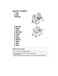
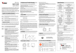
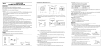
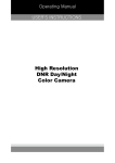
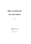
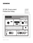
• Avoid using the WAT-231S2 near any strong electro-
magnetic field.
After installing into main equipment, if the WAT-231S2 is
exposed to electromagnetic waves causing the monitored
image to become distorted, we recommend the camera be
shielded by appropriate protective casing.
Color CCD Camera
WAT-231S2
Operation Manual
This Operation Manual covers safety, camera functions, installation and the
correct operating procedure for the WAT-231S2. First, we ask you to read
this Operation Manual thoroughly, then install and operate the WAT-231S2
as advised. In addition, for future reference, we also advise safekeeping of
this manual.
Please contact the distributor or dealer from which the WAT-231S2 was
purchased, if you do not understand the installation, operation or safety
instructions laid out in this manual. Not understanding the contents of the
Operation Manual sufficiently may cause damage to the camera.
Problems and Trouble Shooting
If any of the following problems occur when using the WAT-231S2,
• An optimal picture cannot be obtained, after checking that all the cables
and connections are correctly in place
• Smoke or any unusual odor emerges from the WAT-231S2.
• An object becomes embedded or a quantity of liquid seeps into the camera
housing
• More than the recommended voltage or/and amperage has been applied
to the WAT-231S2 by mistake
• Anything unusual occurring to any equipment connected to the
WAT-231S2.
Guide to the Safety Symbols
The definitions of the symbols used in this operation manual are:
Danger
Warning
Caution
When you do not adhere to or take notice of the “Danger” sign, it
may lead to a serious accident such as death or injury caused by
fire or electric shock.
When you do not adhere to or take notice of the “Warning” sign,
it may cause severe damage such as a physical injury.
When you do not adhere to or take notice of the “Caution” sign, it
may incur injury and cause damage to peripheral objects in the
immediate surroundings.
Disconnect the camera immediately according to the following procedures:
①Switch off the main power supply to the camera.
②Remove the power and video cables connected to the WAT-231S2.
③Contact the distributor or dealer from which the WAT-231S2 was
purchased.
About EMC
The WAT-231S2 is in conformity with EMC test standards carried out by
authorized organizations in Japan.
NTSC
PA L
Cautions for Safety
Danger
The WAT-231S2 is designed to be used safely; however, it may lead to
physical accident caused by fire and electric shock if not used correctly.
Therefore, please keep and read the “Cautions for safety” below for
protection against accidents.
Danger
Warning
Caution
• Do not disassemble and/or modify the WAT-231S2.
FCC Part15 class B
EN61000-6-3/EN50130-4
Power Supply
Do not modify the WAT-231S2. A modified camera may not
conform to EMC test standards.
Contents
Using the contents figures below, check to make sure all parts are present
before use.
• Use only the AD901-120/230 or equivalent power adaptor
Hex. Wrench
Lens Mount Cap
WAT-231S2
DC Plug
Iris Connector
Description of Parts
Caution
The wiring on the connector must be exact.
Be careful no to touch the other terminal while wiring.
Protect the wiring portion by using insulation tape
after wiring. If the above care and attention is not
adhered to, damage to the WAT-231S2 and power
adaptor may occur and may also cause fire.
DC+12V
COMMON(GND)
Auto-iris Lens
Before connecting the auto-iris lens, please make sure that the pin
configuration is correct by checking with the following table. If the
configuration of your iris connector is different from the following, the plug
and pins will need to be rewired.
④
• Avoid the striking of hard objects or dropping the WAT-
231S2.
The WAT-231S2 uses high quality electrical parts and precision
components.
• Do not connect any power supply directly to the video out
terminal of the unit.
Do not connect the WAT-231S2 with any monitor using a
video/power single transmission terminal. The WAT-231S2 is
not designed for use with this type of equipment. We also
advise you to read the operation manual of the monitor you
plan to use before any connections are made.
• Do not install the WAT-231S2 in a position subject to direct
sunlight.
Sunlight shinning directly onto the WAT-231S2 lens can cause
damage to the CCD.
• Select a stable place for installation of the WAT-231S2.
Use a support of durable strength around an installation
position on a ceiling or wall when a camera stand or tripod is
used.
• Do not move the WAT-231S2 with the cables connected.
Before moving the WAT-231S2, always remove the video
cable and power cable from the rear of the camera first.
If any other power adaptor besides the AD901-120/230 is used, please use
a stabilized power adaptor designed for DC+12V±10%, with a current
capacity of more than 250mA.
Use the optional DC plug if the shape or polarity of the DC plug of the power
adaptor to be used is not compatible with the camera (See the drawing on
the right below).
Warning
• Do not operate the WAT-231S2 with wet hands.
for the WAT-231S2.
The recommended voltage is DC+12V±10%
• Do not expose the WAT-231S2 to wetness or high moisture
conditions.
The WAT-231S2 is designed and approved for indoor use only.
The WAT-231S2 is not water-resistant or waterproof. If the
location of the camera is outdoors or in an outdoor like
environment, we recommend that you use an outdoor camera
housing.
• Protect the WAT-231S2 from condensation.
Keep the WAT-231S2 dry at all times during storage and
operation.
• Should the camera not work properly, switch off the power
immediately. Then check the camera according to the
“Problems and Trouble shooting” section.
⑤AUTO-IRIS SOCKET
・This socket is for a video or DC auto-iris lens cable connector.
(Video/DC: Auto selected by the camera)
⑥TRIPOD MOUNTING SCREW HOLES
・Mounting holes for stands. The size of these threads are 1/4”, 20 threads,
4.5±0.2mm, which is the same as any standard camera tripod (U1/4”).
⑦WHITE BALANCE MODE SELECTOR
・The selector for the white balance mode.
⑧PUSH BUTTON (R) (MWB mode)
・The button for adjustment of the white balance to increase the red hue of a
monitored image using M.W.B mode.
⑨PUSH BUTTON (B) (MWB mode)
・The button for adjustment of the white balance to increase the blue hue of
a monitored image using MWB mode.
⑩VIDEO OUT (BNC)
・The terminal for composite video signal output
⑪Y/C OUT
・The terminal for Y/C signal output
⑫POWER IN
・The terminal designed for the DC-plug of the power adaptor
⑬FUNCTION SWITCHES
・Functional switches for setting AGC, BLC and gamma control.
⑭MGC VOLUME ADJUSTING
・The volume for setting manual gain control
⑮AE MODE CONTROL
・The switch for the electronic shutter mode control according to the object
being monitored.
⑯WHITE BLEMISH CORRECTION BUTTON
・The button for correction of white blemish.
③
②
Pin No.
EIAJ Video
Auto-iris Lens
Arrangement
EIAJ DC
Auto-iris Lens
Arrangement
①
①
②
③
④
Power
Not used
Iris signals
Common (GND)
Control -
Control +
Drive +
Drive -
5) Insert the power plug of the power adaptor to ⑫POWER IN on the back
panel of the WAT-231S2. Confirm that the power adaptor is not
connected to the power supply before insertion of the power plug into
⑫POWER IN.
6) Turn on the power to the WAT-231S2, monitor and all other allied
equipment. When a picture cannot be obtained on the monitor, or a
problem occurs, check and follow the procedure mentioned in the
【Problems and Trouble Shooting】section.
7) After following the procedure below and the picture is still out of focus,
open the iris fully and loosen ④FOCUSING ADJUSTMENT SCREWS
with the hex. wrench and move the lens forwards until a clear picture is
obtained.
Adjust the focus and iris to the best position
Manual Lens
on the lens.
Video Auto-iris Lens Adjust the focus on the lens.
Adjust the iris level on the camera, then
DC Auto-iris Lens
adjust the focus on the lens. See below.
Iris Level Adjustment (for DC auto-iris lenses only)
Adjust ③IRIS LEVEL VOLUME placed on the side
of the unit until an acceptable light level is attained.
No change will occur if a video iris lens or manual
iris lens is fitted.
①CCD FRONT FACE
・The light receiving face of the CCD camera
(Dirt, water or oil deposits on the CCD will cause an unclear picture on the
monitor. Attach the lens cap to protect the lens and CCD from
contamination and damage.)
②LENS MOUNT
・Mount for the lens (Thread type)
③IRIS LEVEL VOLUME
・By controlling the volume, the iris level of a DC iris lens can be adjusted.
④FOCUSING ADJUSTMENT SCREWS
・There are 3 hex. adjustment screws each placed at intervals of 120゜for
fine focusing of the lens.
OPEN
LEVEL
8) Select any required shutter speed by the ⑮AE MODE CONTROL to one
of its 10 positions. (Shutter mode is set to 8 upon shipment)
No.
Mode
0
1
2
3
4
5
6
7
8
9
OFF
FL
ES
ES
ES
ES
ES
ES
EI: OFF
EI: FL
Shutter Speeds (Sec.)
NTSC
PAL
1/60
1/50
1/100
1/120
1/250
1/500
1/1000
1/2000
1/4000
1/10000
1/60-1/100000
1/50-1/100000
AE Mode
OFF
Effect
Fixes the shutter speed to NTSC: 1/60, PAL: 1/50.
Reduces the flickering phenomena occurring on the
FL
monitor screen caused by fluorescent or mercury
lamps.
Fixes the shutter speed in a range between 1/250ES
1/10000. (6 steps)
Automatically selects the shutter speed according to
OFF the lighting conditions, retaining the proper exposure
mode. (Electronic Iris)
EI
For electronic iris reducing the flickering phenomena
FL
occurring on the monitor screen caused by fluorescent
or mercury lamps.
※In EI mode, intense light may leave a trail on the screen longitude. This
smearing is a natural phenomenon and is not due to equipment failure
or fault.
9) Select any required white balance mode by ⑦WHITE
BALANCE MODE SELECTOR. (Shutter mode is set to
AUTO upon shipment)
Mode
Name
AUTO
Auto-tracking
MWB
Manual
PWB
Push-lock
Set-up and Operation
1) Ensure that the power to the WAT-231S2 and the peripheral equipment is
turned off before making any connections.
2) Remove the lens mount cap from the WAT-231S2 and attach the
CS-mount lens. Use the optional C-mount adaptor (34CMA-R) when a
C-mount lens is used.
3) Connect the iris control cable to ⑤AUTO-IRIS SOCKET on the WAT231S2 when an auto-iris lens is being used.
4) Connect ⑩VIDEO OUT on the WAT-231S2 with the monitor, using a
coaxial cable with 75Ω impedance, such as an RG-58/U or an RG-6/U.
If the monitor has an S-terminal, high resolution imaging is possible by
connecting with ⑪Y/C OUT.
※The ⑪Y/C OUT can be used together with the ⑩VIDEO OUT.
※Select a monitor with the same television system as the WAT-231S2
iNTSC or PAL. A monitor with more than 600TV lines is recommended.
CLOSED
Lock
1
2
Incandescent
(=3200K)
Fluorescent 1
(=4300K)
Fluorescent 2
(=5100K)
Sunlight
(=6300K)
Effect
Automatically follows and adjusts to the
changing color temperature of the
illumination.
Manual adjustment using ⑧⑨PUSH
BUTTON(R)(B) as required.
Adjusted with ⑨PUSH BUTTON(B)
according to the color temperature of the
environment. As long as (B)button is
pressed, the color temperature is
adjusted according to the environment.
As soon as the (B)button is released, the
color temperature will be fixed at that
setting.
To lock your manually adjusted color
temperature settings.
Color correction to give natural color
renditions under incandescent lighting.
Color correction to give natural color
renditions under reddish fluorescent light.
Color correction to give natural color
renditions under bluish fluorescent light.
Used in sunlight to retain white balance.
10) Set the ⑬FUNCTION SWITCHES according to
your requirements.
ON
Specifications
1 2 3 4
Switch
Setting
ON
1.
AGC
2.
AGC
3.
BLC
4.
Gamma
correction
Effective Condition (Example)
Factory
Settings
・When sensitivity is more
iimportant than the SN ratio.
・When an auto iris lens can not
be used for general surveililance purposes.
・Increase the MGC in a low light
environment when object
OFF
illumination is important. Lower
【MGC】
the gain control for a clearer
picture with less noise.
ON
・When sensitivity is more impor
【HI】
--tant than the SN ratio
OFF
・When SN ratio is important
【LO】
and AGC is also required.
・When the picture of the
monitored object is silhouetted
ON
due to strong lighting from
above or behind.
・When the illumination
OFF
differences between a
imonitored object is narrow.
・Applicable to a general surveilON
ilance monitoring system
・When gamma correction is not
OFF
required for image processing
11) Set the gain to the required environment by ⑭MGC VOLUME
ADJUSTING. Manually adjusted in a range between 0 to 32dB. In a low
light environment, when illumination of the object is important, increase
the manual gain. Lower the gain control for a clearer picture with less
noise.
12) Correction of white blemish by ⑯WHITE BLEMISH CORRECTION
BUTTON. The WAT-231S2 is manufactured using high-grade CCD
devices that are selected by tough standards by the manufacturer.
However, it is impossible to prevent the white blemishes from occurring
after shipment because the white blemish phenomena can be caused
by cosmic rays. The WAT-231S2 has a white blemish correction circuit
to help control the white blemish phenomena. Correct according to the
following procedures, if white blemishes are present.
[PROCEDURE]
1. Completely cover the lens to prevent light entering.
2. Set to MWB or PWB by ⑦WHITE BALANCE MODE SELECTOR
3. Set to AGC ON by ⑬FUNCTION SWITCHES
4. Press the ⑯WHITE BLEMISH CORRECTION BUTTON using a fine
stick or piece of wire.
5. After 5 seconds, the white blemishes are automatically detected, and
then recorded to the camera.
[ATTENTION]
1) Make sure that the lens is completely shielded from light before
correction of the white blemishes. If the lens is not covered properly
and light can enter into the lens on to the CCD face, the correction of
the white blemish may not be detected correctly.
2) Make sure that ⑦WHITE BALANCE MODE SELECTOR ”MWB or
PWB” is selected. If any other position is selected; the data cannot
be saved to the camera.
Model
WAT-231S2 (NTSC)
Pick-up Element
WAT-231S2 (PAL)
1/3 inch interline transfer CCD image sensor
Number of Total Pixels
811(H)×508(V)
795(H)×596(V)
Number of
Effective Pixels
768(H)×494(V)
752(H)×582(V)
Unit Cell Size
6.35um(H)×7.4um(V) 6.5um(H)×6.25um(V)
Imaging system
Ye, Cy, Mg, and G complementary
color mosaic filters on chip
Sync. System
Internal
Scanning System
2:1 interlace
Video Output
Composite, Y/C: 1.0V(p-p) 75Ω (Unbalanced)
Resolution (H)
More than 540TVL (Center, Y/C)
Minimum Illumination
0.05 lx F1.2
S/N
More than 50dB (MGC=0dB, γ=1.0)
AE Mode
OFF
1/60 sec.
1/50 sec.
FL
1/100 sec.
1/120 sec.
ES
EI: OFF
EI: FL
1/250, 1/500, 1/1000,
1/2000, 1/4000, 1/10000 sec.
1/60-1/100000 sec.
1/50-1/100000 sec.
White Balance
ATW, PWB, MWB,
3200K, 4300K, 5100K, 6300K
AGC
HI: 0-38dB / LO: 0-32dB
MGC
0-32dB
Gamma Characteristics
γ≒0.45(ON) /γ=1.0(OFF)
Lens-iris
Video / DC (EIAJ arrangement, Auto-select)
Back Light
Compensation
White blemish
Correction
Power Supply
ON / OFF
Up to 32 dots
DC+12V±10%
Power Consumption
2.1W (175mA)
Operating Temperature
-10 - +50℃ (Without condensation)
Operating Humidity
Less than 95% RH
Storage Temperature
-30 - +70℃ (Without condensation)
Storage Humidity
Less than 95% RH
Lens Mount
CS-mount
Size
44.5(W)×44(H)×64(D) (mm)
Weight
Approx. 160g
• Design and specifications are subject to change without notice.
• Watec is not responsible for any inconvenience or the attendant damages
to the video and monitoring recording equipment caused by misuse, misoperation or improper wiring of our equipment.
• If for any reason the WAT-231S2 does not work properly, or if you have
any questions regarding installation or operation, please contact the
distributor or dealer from which it was purchased.
Options
To purchase these options, please contact the distributor or dealer from
which you purchased the WAT-231S2.
Contact information
Watec Co., Ltd.
AC Adaptor (AD901-120/230)
The recommended AC adaptor for
the WAT-231S2 for a constant and
stable power supply.
C-mount Adaptor (34CMA-R)
Add.:
254-2 Nihonkoku, Daihoji, Tsuruoka- Shi,
Yamagata-Ken, 997-0017 Japan
TEL:
+81-235-23-4400 FAX: +81-235-23-4409
Email: [email protected]
URL:
http://www.watec.net
This lens mount adaptor is used to
convert a CS-mount to a C-mount.
Mini Stand (MS50)
A convenient stand for the
WAT-231S2. With this stand, the
camera can be adjusted to any
desired angle.
1453Z00-Y2000001