1
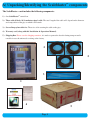
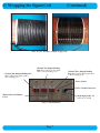
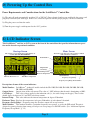
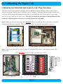
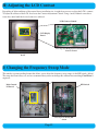
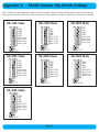
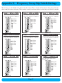
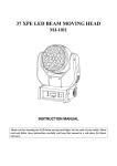
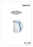
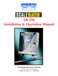
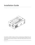
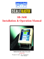
SB-3600
Installation & Operation Manual
Industrial Electronic Descaler
115/230 VAC
For pipe sizes up to: 36" -non-ferrous
12-24" -ferrous
Table of Contents
Section
A)
Description
Unpacking and Identifying the Scaleblaster components..........................................................
Page
4
B)
Installing the Scaleblaster Control Box.....................................................................................
5
C)
Wrapping the Signal Coil..........................................................................................................
6,7
D)
Powering up the Control Box....................................................................................................
8
E)
LCD Indicator Screen................................................................................................................
8
F)
Error Screen and Codes.............................................................................................................
9
G)
Calibrating the Signal Coil........................................................................................................
10,11
H)
Adjusting the LCD Contrast......................................................................................................
12
I)
Changing the Frequency Sweep Mode......................................................................................
12
J)
Attaching an External Alarm/Fault Indicator............................................................................
13
Appendix 1)
Model Number Dip Switch Settings.......................................................................
14
Appendix 2)
Frequency Sweep Dip Switch Settings...................................................................
15
Appendix 3)
Unit Specifications..................................................................................................
16
Notes)
_________________________________________________________________________
Product Information
Page 3
17,18
TM
A) Unpacking/Identifying the Scaleblaster components
The ScaleBlasterTM unit includes the following components:
1.) One ScaleBlasterTM control box.
2.) Three rolls of black, 18/3-conductor signal cable. The total length of the cable will depend on the diameter
and composition of the pipe to which it will attach.
3.) Several long nylon cable ties. These ties aid in securing the cable to the pipe.
4.) Warranty card (along with this Installation & Operations Manual).
5.) Shipping Box. Please save the shipping container, it is made to protect the descaler during transport and is
reusable in case the unit needs servicing at the factory.
2
2
3
1
4
5
Page 4
B) Installing the Scaleblaster Control Box
TM
Selecting the Installation Location and Mounting the ScaleBlasterTM Unit
PLEASE READ THE ENTIRE MANUAL BEFORE BEGINNING INSTALLATION. THE LOCATION
OF THE SIGNAL CABLE AND THE CONTROL BOX ARE CRITICAL WITH RESPECT TO PRODUCT
PERFORMANCE.
1.) The unit should be installed by a licensed electrician, and the installation should meet all local and national codes.
2.) The best place to install the unit is on the main water line entering the facility, or on the line serving the relevant
portion of the facility. First determine where the signal coils will be wrapped. This should be on a straight section of
pipe (no elbows, tees, valves or couplings) that is at least four (4) feet long. Also, very important, the signal coils
should be at least three (3) feet from any major source of electrical interference. The unit is splash-proof and can be
installed outside if necessary. However, in this case a cover should be installed above the unit, and the unit should be
kept out of direct sunlight.
3.) Mount the control box as close as possible to where the signal cable will wrap on the pipe, so that the cable is as
short as possible.
4.) The control box, which has a 15-ft. power cord, should be mounted on a wall or other solid surface in a location
near an electrical outlet or other power source. The unit is heavy and a sturdy installation is required. We recommend
that you use a 3/8" lag and washer for each of the four mounting feet. (See photos below.)
5.) Upon being plugged in, the unit will work automatically on either 115 VAC or 230 VAC.
NOTE: If you have any questions about installation, contact your dealer or Clearwater Enviro Technologies, Inc.
for assistance.
Photo 1 - recommended 3/8" mounting lag with washer.
Page 5
Photo 2 - one of the four control box mounting feet.
C) Wrapping the Signal Coil
Wrapping the Signal Cable Around the Pipe
Included with the unit is one roll of black, 3-conductor signal cable whose length is based on the size and
composition of the pipe selected for installation.
1.) Carefully strip off 2" (51mm) of the outer rubber shield from the end of the signal cable. Next, strip off 2" (51mm)
of the insulation from each of the three conductor wires (black, white and green). Splice the three wires together
tightly (see Photo 3, below).
2.) Unscrew the first of the two receptacle posts for that coil (see Photo 5, next page) by turning it counter-clockwise
to create an opening. Then, with the spliced wires of the signal cable completely threaded through the opening,
tighten the receptacle post as much as possible (see Photo 3, below).
3.) Route the signal cable from the control box to the inlet pipe. Hold the cable parallel and against the pipe and then
secure the cable to the pipe with one of the nylon cables ties. Make sure that the tie is pulled tightly so that the cable
is well-attached to the pipe. Remove excess cable tie with scissors.
4.) Using finger pressure to keep the signal cable and tie from moving, begin wrapping the signal cable securely
around the pipe in any direction. The correct number of wraps depends on pipe size and composition. For proper
product performance, it is imperative to wrap the correct number of times. To determine the number of wraps for
ferrous pipe, consult Table 1 (below). For non-ferrous pipe, please call ClearWater Enviro Technologies, Inc. to get
this information.
5.) MAKE SURE THAT THE WRAPS ARE FLUSH AGAINST ONE ANOTHER–NEVER OVERLAPPING
(see Photo 4a & 4b, next page).
NOTE: As previously indicated, make sure that the control box is mounted as close as possible to where the signal
cable is wrapped on the pipe.
Pipe
Size
12" / (30.48cm)
14" / (35.56cm)
16" / (40.64cm)
18" / (45.72cm)
20" / (50.8 cm)
24" / (60.96cm)
Nominal
Pipe OD
13" / (31.75cm)
15" / (36.83cm)
17" / (43.18cm)
19" / (48.26cm)
21" / (53.34cm)
25" / (63.5 cm)
Circumference
39.27" / (99.74cm)
45.55" / (115.7 cm)
53.41" / (135.65cm)
59.69" / (151.61cm)
65.97" / (167.57cm)
78.54" / (199.49cm)
Number
of Wraps
37
34
31
28
25
22
Total Length
Coil Only
121' / (307.54cm)
129' / (327.82cm)
138' / (350.43cm)
139' / (353.75cm)
137' / (349.1 cm)
144' / (365.72cm)
Total Length
w/ 15' Coil Leads
151' / ( 384cm)
159' / ( 404cm)
168' / ( 427cm)
169' / ( 430cm)
167' / ( 425cm)
174' / ( 442cm)
Table 1 - Ferrous Pipe: Number of Wraps by Pipe Size
6.) Once the wrapping is complete, secure the signal cable
to the pipe using another cable tie. Remove the excess cable
tie with scissors.
7.) Route the loose end of the signal cable back to the
control box. Trim the cable to length.
Photo 3 - Signal coil end with three wires stripped and
braided together
Page 6
C) Wrapping the Signal Coil
(Continued)
Photo 4a & 4b - Examples of tightly wrapped coils
Channel One Output Binding Post
Set: Connect first signal cable to
these binding posts.
Channel Two Output Binding
Post Set: Connect second signal
cable to these binding posts.
Channel Three Output Binding
Post Set: Connect third signal cable
to these binding posts.
Power Switch
K-Flex Conduit Connector
Model and Serial Number
Label
Main Input Cable: 90264 VAC, 47-63Hz
Photo 5 - Unit Gland Plate
Page 7
D) Powering Up the Control Box
Power Requirements and Considerations for the ScaleBlasterTM Control Box
1.) The unit will work automatically on either 115 or 230 VAC. Since electrical outlets vary worldwide, the power cord
plug may not match your outlet type. In this case, it must be replaced with the proper plug by a licensed electrician.
2.) Plug the power cord into the outlet.
3.) Turn the power toggle switch upward to the “ON” position.
E) LCD Indicator Screen
This ScaleBlasterTM unit has an LCD screen on the front of the control box that provides information on operation on the descalers operational condition.
Start-up Screen
Main Screen
The start-up screen is displayed for approximately 10
seconds while the unit initializes.
The main screen show most of the operation condition
of the Scaleblaster control box.
Model Number
Output Status
Coil Voltage
Internal Temperature
Enclosure Temperature
Firmware Revision Level
Channel Number
Total Hours of Operation
Frequency Sweep Range
Frequency Sweep Range Mode Number
Descriptions of some of the screen indicators:
Model Number: ScaleBlasterTM ‘industrial’ models include the SB-1200, SB-1400, SB-1800, SB-2000, SB-2800,
SB-3600, and SB-4000.
Output Status: Output status of the coil current. The value of “100” indicates that the unit is functioning at 100%.
Coil Voltage:
This is the voltage applied to the induction coil (i.e., the coiled wraps on the pipe). These values
should always be between 19.5 and 20.5 volts direct current.
Internal Temp: This value indicates the internal temperature in degrees Fahrenheit.
Enclosure Temp: Displays the temperature, in degrees Fahrenheit, of each channel’s heatsink.
Frequency Sweep Range: Frequency range the descalers output will sweep between.
Mode Number: This number identifies a particular frequency sweep range, as set by the DIP switch. The unit is
designed to permit selecting from among several pre-set sweep ranges via the DIP switch. (See “Additional Options:
Frequency Sweep Mode”, p. 12.)
Page 8
F) Error Screen and Codes
This ScaleBlasterTM unit constantly scans for any malfunctions in the operation status of the unit. If an error is
detected it is logged reported via the Unit Error Screen. This screen will display the channel and error that has
occurred. A brief description of these errors are described below.
Error List: Displays channel number
and type of error that has occurred. List
holds up to four errors.
Error: In this example, the reading of
“000” for the output status indicates a
problem with the current at the coil for
Channel 1.
Sample Error Screen
INTERNAL TEMP Error
Displayed as:
CH-1(2,3) INTERNAL TEMP
The internal temperature sensor has recorded a temperature that is too high (above 150º F , 65.6º C) and has shut
down that channel. One possible cause for this error is that the unit was installed in a location exposed to direct
sunlight, which may make the unit overheat. Another possible reason for this is a failure of internal circuitry causing
excess heat buildup. In this case, contact your dealer or ClearWater Enviro Technologies, Inc.
ENCLOSURE TEMP Error
Displayed as:
CH-1(2,3) ENCLOSURE TEMP
Enclosure and slave board heatsink temperature sensor has recorded a temperature that is too high (above 150º F ,
65.6º C) and has shut down that channel. Possible cause for this error: internal circuitry failure. Contact your dealer or
ClearWater Enviro Technologies, Inc.
SMPS VOLTAGE Error
Displayed as:
CH-1(2,3) SMPS VOLTAGE
The value shown at “Coil Voltage” is the main output in volts from the Switch Mode Power Supply located inside
the control box. If this error occurs, check the output binding posts for that channel to make sure that they are not
directly shorted together. If not, then there must be a failure of internal circuitry. Contact your dealer or ClearWater
Enviro Technologies, Inc.
COIL CURRENT Error
Displayed as:
CH-1(2,3) COIL CURRENT
This indicates a failure in the main output current for that channel. Possible cause: the cable wire has been cut or
disconnected from the output binding post.
Page 9
G) Calibrating the Signal Coil
Calibrating the Industrial unit to match Coil / Pipe Variations
The unit has been factory calibrated to the pipe similar to that of the actual installed pipe. However there may be
differences in the pipe material, pipe wall thickness, and coil wrapping techniques witch may require the unit to be
re-calibrated. The following will instruct the installer how to accomplish this task. Tools required, a large regular
screw driver, and a small jewelers screw driver. Note that even though the instructions are using different models
to show the calibration process, the process is vertually identical for each model.
Step 1) Make sure unit is at room temperature, DO NOT calibrate unit while the unit is warm. Please wait till the
unit has returned to room temperature. Then, open the door on the unit using the large regular screw driver.
Control unit with door closed.
Control unit door open showing electronics inside.
Step 2) Use the small jewelers screwdriver to move the bottom four dip switches to the positions shown in the
picture below.
Note: DO NOT move any of the top four dip switches.
Don’t Care
Don’t Care
Don’t Care
Don’t Care
OFF
OFF
OFF
ON
View of the master board showing
location of Dip Switch.
Close up view of the dip switch Set for calibration
mode.
Page 10
G) Calibrating the Signal Coil
(Continued)
Step 3) Locate the slave board, and the small blue potentiometer located at the upper right side of that board.
View View showing all
boards.
Close up view of slave board.
Close up view of potentiometer on slave board.
Step 4) With the coil attached, power up unit and notice that it now comes up in calibration mode (M9).
Step 5) Now the unit is in calibration mode, the output power reading is changed
in this mode to display the under/over current error trip point. This reading should
be between 40 and 60. If output power is lower then 040, then using the small
jewelers screwdriver, turn the small screw on the blue potentiometer, (the blue
square thing) clock wise, this will increase the output power reading. Likewise if
the output power reading is more then say 060, adjust the potentiometer counter
clockwise till it is between 40-60. Please note that the exact reading is not critical,
and where from 40 to 60 will allow the unit to operate with in the normal operating
parameters.
View of the units screen in
normal mode (M4).
Note if the unit is not responding to the above calibration then, turn the potentiometer 20 full turns counter-clockwise. This will reset the unit to its default minimum
value. Then repete step 5.
Note this will not increase the output power. This adjustment is for the internal
microcontroller reference for sensing over and under current conditions and has
Step 6) Once the adjustment has been
made, power down unit and reset the bottom
four dip switches back to the normal operating mode, 1KHz to 20KHz (M4).
View of the units screen in
calibration mode (M9).
Don’t Care
Don’t Care
Don’t Care
Don’t Care
ON
ON
OFF
OFF
View of the Dip Switch Set for normal mode.
Page 11
H) Adjusting the LCD Contrast
Depending of light conditions of the control boxes installation site, it might be necessary to adjust the LCD’s contrast.
To adjust the contrast of the LCD, first locate the Contrast Adjustment Control. Using a small, flathead screwdriver,
rotate the control until the desired contrast is achieved.
LCD Contrast Control
LCD Display
Board
Close-up of LCD Display Board showing the
Contrast Control
Back of door showing the LCD Display
Board
I) Changing the Frequency Sweep Mode
This unit has a patent-pending feature that allows you to adjust the frequency sweep range via the DIP switch ( below).
The range has been factory set, and we recommend that you do not change this without first consulting ClearWater’s
engineers.
Main Control
PC Board
DIP Switch
Close-up view showing DIP
Switch
View of Main Control PC Board
Page 12
J) Attaching an External Alarm/Fault Indicator
All units come with the option of adding an alarm or fault indicator to instantly alert you of any power failure or equipment malfunction. The Terminal Strip (shown below) permits the addition of any type of external alarm system, light, or
dial-up to a phone, beeper, etc. Provided these components do not exceed 240vac @ 10amp, and are not inductive in
nature. Contact your dealer or ClearWater Enviro Technologies, Inc. for more details.
Location of Terminal Strip
Internal
Control
Box
Close-up view of Terminal Strip
Alarm fuse, 10amp, 240VAC, Slow Blo, 5x20mm
Relay shown in normal
(non-fault) position
External Alarm or
Indicator
Alarm Relay and Fuse location.
Diagram showing a typical hookup for a light or
siren to activate if a unit fault is detected.
Page 13
Appendix 1)
Model Number Dip Switch Settings
This is factory set and should not be adjusted by the end user. These switches will not increase the power to the unit,
that can only be done at the factory. These settings are only for reference in the case that they were altered by mistake.
SB-1200 Mode
OFF
OFF
OFF
OFF
Don’t Care
Don’t Care
Don’t Care
Don’t Care
SB-2000 Mode
ON
ON
OFF
OFF
Don’t Care
Don’t Care
Don’t Care
Don’t Care
SB-1400 Mode
ON
OFF
OFF
OFF
Don’t Care
Don’t Care
Don’t Care
Don’t Care
SB-2800 Mode
OFF
OFF
ON
OFF
Don’t Care
Don’t Care
Don’t Care
Don’t Care
SB-4000 Mode
OFF
ON
ON
OFF
Don’t Care
Don’t Care
Don’t Care
Don’t Care
Page 14
SB-1800 Mode
OFF
ON
OFF
OFF
Don’t Care
Don’t Care
Don’t Care
Don’t Care
SB-3600 Mode
ON
OFF
ON
OFF
Don’t Care
Don’t Care
Don’t Care
Don’t Care
Appendix 2)
Frequency Sweep Dip Switch Settings
This is factory set and should not be adjusted by the end user. These switches will not increase the power to the unit,
that can only be done at the factory. These settings are only for reference in the case that they were altered by mistake.
Mode 1 - 1KHz to 5KHz
Mode 2 - 1KHz to 10KHz
Mode 3 - 1KHz to 15KHz
Sets the frequency sweep range of the unit
to sweep from 1,000 hertz to 5,000 hertz.
Sets the frequency sweep range of the unit
Sets the frequency sweep range of the unit
to sweep from 1,000 hertz to 15,000 hertz.
Don’t Care
Don’t Care
Don’t Care
Don’t Care
OFF
OFF
OFF
OFF
to sweep from 1,000 hertz to 10,000 hertz.
Don’t Care
Don’t Care
Don’t Care
Don’t Care
OFF
ON
OFF
OFF
Don’t Care
Don’t Care
Don’t Care
Don’t Care
ON
OFF
OFF
OFF
Mode 4 - 1KHz to 20KHz
Mode 5 - 1KHz to 2KHz
Mode 6 - 2KHz to 4KHz
Sets the frequency sweep range of the unit
to sweep from 1,000 hertz to 20,000 hertz.
Sets the frequency sweep range of the unit
Sets the frequency sweep range of the unit
to sweep from 2,000 hertz to 4,000 hertz.
Don’t Care
Don’t Care
Don’t Care
Don’t Care
ON
ON
OFF
OFF
to sweep from 1,000 hertz to 2,000 hertz.
Don’t Care
Don’t Care
Don’t Care
Don’t Care
OFF
OFF
ON
OFF
Mode 7 - Cal. Auto Tune
Mode 8 - Use Auto Tune
Future Use
Future Use
Don’t Care
Don’t Care
Don’t Care
Don’t Care
ON
OFF
ON
OFF
Mode 9 - Calibrate Coil
Use to calibrate the signal coil to the
Scaleblaster unit.
Don’t Care
Don’t Care
Don’t Care
Don’t Care
OFF
ON
ON
OFF
Don’t Care
Don’t Care
Don’t Care
Don’t Care
ON
ON
ON
OFF
Page 15
Don’t Care
Don’t Care
Don’t Care
Don’t Care
OFF
OFF
OFF
ON
Appendix 3)
Unit Specifications
SB-3600 Electronic Descaler
Specification Sheet
Input Voltage:
Input Current:
No. Channels:
Output Voltage:
Output Current:
Output Signal:
90-264 VAC at 47-63 Hz
5A rush @ 115 VAC, 1A rush @ 230 VAC
Three
20 VDC
10 Amps Peak Min. @ 1KHz on all 3 channels**
AC Square wave, Frequency user selectable:
Swept frequency from 1KHz to 5KHz
Swept frequency from 1KHz to 10KHz
Swept frequency from 1KHz to 15KHz
Swept frequency from 1KHz to 20KHz
Swept frequency from 1KHz to 2KHz
Swept frequency from 2KHz to 4KHz
Circuit Protection:
···
··
··
Enclosure:
Thermal overload protection on Switch-Mode Power Supply (SMPS)
Over voltage protection on SMPS
Over current protection on SMPS
Micro-controller monitoring of enclosure/heatsink over temperature shutdown
Micro-controller monitoring of internal over temperature shutdown
Output sensing circuit for over current immediate shutdown protection
Main input noise filtering
Wall mount, beige powder-coated, 16-gauge steel. Nema 4 and 12 rated. With Gland Plate and
polycarbonate window.
Operating Temperature:
10º F to 130º F (12º C to 54º C)
Storage Temperature:
2º F to 150º F (17º C to 66º C)
Physical Properties:
SB-3600 Unit Dimensions: 24”x20”x8” (61cm x 50.8cm x 20.3cm)
SB-3600 Unit Weight: 25 LBS (66.2 Kg)
SB-3600 Shipping Crate Dimensions: 26”x30”x14”
SB-3600 Shipping Weight: 146 LBS*
* Estimated shipping weight. (Varies with differing amounts of signal cable.)
** Maximum coil inductace: 200uH. (See coil chart.)
Page 16
Notes:
_______________________________________________________________
_______________________________________________________________
_______________________________________________________________
_______________________________________________________________
_______________________________________________________________
_______________________________________________________________
_______________________________________________________________
_______________________________________________________________
_______________________________________________________________
_______________________________________________________________
_______________________________________________________________
_______________________________________________________________
_______________________________________________________________
_______________________________________________________________
_______________________________________________________________
_______________________________________________________________
_______________________________________________________________
_______________________________________________________________
_______________________________________________________________
_______________________________________________________________
_______________________________________________________________
_______________________________________________________________
_______________________________________________________________
_______________________________________________________________
_______________________________________________________________
_______________________________________________________________
_______________________________________________________________
_______________________________________________________________
_______________________________________________________________
_______________________________________________________________
Page 17
Notes:
_______________________________________________________________
_______________________________________________________________
_______________________________________________________________
_______________________________________________________________
_______________________________________________________________
_______________________________________________________________
_______________________________________________________________
_______________________________________________________________
_______________________________________________________________
_______________________________________________________________
_______________________________________________________________
_______________________________________________________________
_______________________________________________________________
_______________________________________________________________
_______________________________________________________________
_______________________________________________________________
_______________________________________________________________
_______________________________________________________________
_______________________________________________________________
_______________________________________________________________
_______________________________________________________________
_______________________________________________________________
_______________________________________________________________
_______________________________________________________________
_______________________________________________________________
_______________________________________________________________
_______________________________________________________________
_______________________________________________________________
_______________________________________________________________
_______________________________________________________________
Page 18
Clearwater Enviro Technologies, Inc.
1166 Kapp Drive, Clearwater, FL, 33765
Phone: 800-756-7946 or 727-562-5186 Fax: 727-562-5187
or visit us on the web at www.clearwater-enviro.com