1
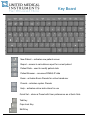
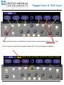
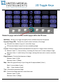
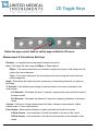
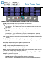
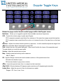
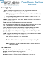
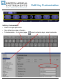
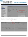
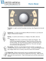
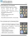
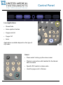
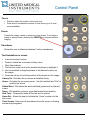
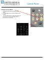
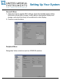
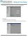
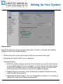
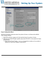
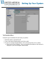
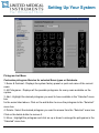
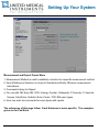
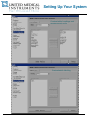
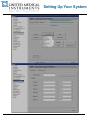
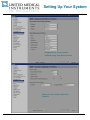
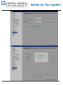
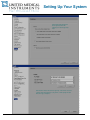
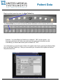
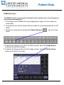
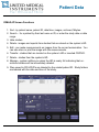
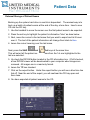
ACUSON X300™ PE
ACUSON X300™ CONTROL PANEL
The ACUSON X300 knobology and user guide is the clinicians quick reference of
system terms, functions and capabilities.
This guide was created to simplify the information contained within the Siemens
ACUSON X300 PE User Manual.
For more detailed information please refer to your Siemens User Manual. For your
convenience, the Siemens User Manual pages that correspond to the content in this
guide, are reference at the bottom of each page.
Chapter 1, Knobology ……………………………………………………...p 1-2 thru 1-18
Chapter 2, System Setup …………………………………………………p 2-1 thru 2-11
Chapter 3, Patient Data ..…………………………………………………..p 3-1 thru 3-5
Chapter 4, Exam Quick Sets ….…………………………………………p 4-1 thru 4-28
Chapter 5, Phlebology Optimization Guide………………………………p 5-1 thru 5-5
Copyright © 2008-2010 United Medical Instruments Inc.
Key Board
New Patient – activates new patient screen
Report – access to calculations report for current patient
Patient Data – used to modify patient data
Patient Browser – accesses DIMAQ-IP data
Exam - activates Exam Presets for active transducer
Presets - activates system Presets
Help – activates online instructions for use
Quick Set – stores a Preset with User preferences as a Quick Sets
Tab Key
Caps Lock Key
Shift Key
Toggle Keys & Soft Keys
Toggle switches can be adjusted up or down for the corresponding soft key menu item.
Use the page control knob to toggle between 2D, Color and Doppler modalities.
Push down on Page control to change modes
2D Toggle Keys
Rotate the page control knob to switch pages within the 2D menu.
MultiHertz - Allows you to toggle through the three available transducer frequencies.
Dynamic Range (DR) - Controls the overall contrast resolution of the image.
DR adds more shades of grey for a smoother image.
DR removes shades of grey for a more contrasting image.
Persist - Frame averaging function that determines the amount of image motion smoothing.
Minimum Value: 0 - removes history, increasing the frame rate to create a sharper image.
Maximum Value: 4 - adds history to the image, slowing the frame rate to create a smoother
image.
Edge Enhance - Controls the sharpness of edges.
Minimum Value: 0 (Soft)
Maximum Value: 3 (Sharp)
Map - Select the grayscale map of your liking with 9 maps available (A thru I).
Map A (more shades of grey)
Map I
(fewer shades of grey)
Tint - Colorizes the grayscale image
R/S - Controls the image resolution versus frame rate.
Minimum Value: 0 (Soft)
Maximum Value: 5 (Sharp)
2D Toggle Keys
Rotate the page control knob to switch pages within the 2D menu.
Measurement & Calculations Soft Keys
Distance - Is a simple linear measurement between two points.
Area - Calculates the area using the Ellipse or Trace method.
Ellipse - The system determines one diameter using the end points of the ellipse and calculates the second diameter.
Trace - The system determines the circumference and area using the hands free trace
method segments.
Angle - Determines the Angle using two (connecting or intersecting) lines that you place on
the image.
% Stenosis - Calculates the percentage of stenosis based on the area or diameter of the
same vessel.
A-% Stenosis - Calculates the area % stenosis, comparing the cross-sectional areas of
the same vessel.
D-% Stenosis - Calculates the diameter % stenosis, comparing diameters of the same
vessel.
Volume - Performs a volume measurement with either a distance measurement, ellipse
measurement or Trace measurement.
Flow Volume - Measures the distance or area to calculate the blood flow volume.
A-Flow Volume - Is the estimation of blood flow based on the area of the vessel.
D-Flow Volume - Is the estimation of blood flow volume based on the diameter of the
vessel.
Color Toggle Keys
Rotate the page control knob to switch pages within the Color Doppler menu.
TxFreq - Allows you to toggle through the two available color frequencies.
PRF
- Controls the velocity range in color Doppler.
PRF until there is wall to wall color filling without color aliasing for vessels with faster blood
flow, arteries.
PRF until there is wall to wall color filling without overfilling the vessels with slower blood
flow, veins.
Persist - Averages color frames to improve sensitivity and reduce clutter.
Minimum Value 0: (Color corresponding to blood flow is replaced by another, faster rate)
Maximum Value 4: (Color corresponding to blood flow is replaced by another, slower rate)
Filter - Changes the transition point of the clutter filter to enhance low flow versus eliminating clutter
artifacts.
R/S - Adjust the balance between the image line density (resolution) and the frame rate.
The
line density increases resolution and decreases frame rate creating a more compressed image.
Map- Displays measured velocity and/or variances as shades of color.
Priority - Changes the priority of color and B-mode data.
Smooth - Changes the amount of spatial smoothing in the image.
Minimum Value: 0 (Decreased motion smoothing)
Maximum Value: 4 (Increased motion smoothing)
Baseline - Adjusts the relative baseline position up and down. A shift in baseline adjusts the range
of displayed flow velocities without changing the system PRF.
Flow - Optimizes hemodynamic flow conditions by automatically adjusting the wall filter and PRF
parameters for the selected Flow state.
Low - Maximum sensitivity to low velocity flows.
Medium - Balances between suppression and sensitivity of velocity flow.
High - Optimized for the high arterial flow common to pulsatile vessels and stenotic condi-
Doppler Toggle Keys
Rotate the page control knob to switch pages within the Doppler menu.
MultiHertz - Allows you to toggle through the three available transducer frequencies.
PRF - Controls the velocity range in pulse wave Doppler.
PRF to sample increased vessel blood flow, arteries or if the wave form wraps around the baseline .
PRF to sample slower vessel blood flow, veins or to increase the size of the wave form on the baseline.
Baseline - Adjusts the relative baseline position up and down. A shift in baseline adjusts the range of displayed flow velocities without changing the system PRF.
Gate - Adjust the size of the pulse wave gate. Gate should fit within the lumen of the sampled vessel.
The gate should not touch the vessel walls.
Volume - Adjust the spectral wave volume.
Map - Displays measured velocity and/or variances.
Map A - Map H
DR - Dynamic Range controls the overall contrast resolution of the spectral wave form.
DR adds more shades of grey
DR removes shades of grey (more contrast)
Invert - Inverts the spectral wave form to or away from the transducer.
Ang 60/0/60 - Shortcut between 60 degrees angle correction and 0 degrees angle correction.
Update Rate - Adjust the amount of time for the spectrum update.
Ranges: Off, 2 sec, 4 sec, 8 sec
Doppler & M-Mode
Functions
Doppler Toggle Keys
Velocity - Is the Distance over time measurement determined by a measurement marker
placed along a vertical plane.
PI Auto - Use an automatic trace of the spectrum to determine a pulsatility index.
Acceleration - Acceleration or Deceleration of speed over the time traveled determined by two
measurement markers.
Velocity Ratio - Calculate a ratio of two velocity measurements.
HR - Heart rate determined over one heart cycle.
RI - Pourcelot's Ratio: RI = [PS-ED] / [PS] (4)
PI Manual - Use a manual trace of the spectrum to determine a pulsatility index
Flow Volume - Selects methods for estimating blood flow volume.
Time - Interval in milliseconds between two measurement markers.
M-Mode Toggle Keys
MultiHertz - Allows you to toggle through the three available transducer frequencies.
DR - Dynamic Range controls the overall contrast resolution of the M-Mode sweep.
Tint - Colorizes the M-mode sweep.
Edge Enhance - Distinguishes the contours of a structure during real-time imaging.
Sweep - Adjust the scrolling speed of the M-mode sweep.
Map - Selects a processing curve that assigns echo amplitudes to gray levels.
Measurement & Calculations Soft Keys
Distance - Is the vertical distance between two points in the M-mode sweep.
HR - Is determined over one heart cycle in 2D/M-mode.
Slope - Distance over time calculation determined by two distance measurement markers.
Time - Is the interval in seconds between two measurement markers.
Power Doppler Key Mode
Functions
Power Toggle Keys
TxFreq - Allows you to toggle through the two available color frequencies.
PRF - Controls the scale factor assigned to slow flow.
PRF to sample increased vessel blood flow, arteries or if the wave form wraps
around the baseline .
PRF to sample slower vessel blood flow, veins or to increase the size of the
wave form on the baseline.
Persist - Adjusts the time over which power data are processed in calculating the
power amplitude display.
Filter - Balances the low flow sensitivity with flash suppression.
R/S - Adjust the balance between the image line density (resolution) and the frame
rate. The line density increases resolution and decreases frame rate.
Map - Selects a processing curve that assigns flow amplitudes to color levels.
Priority - Adjusts the threshold for the amplitude of the Power display.
Smooth - Adjusts the level of spatial averaging used to smooth the display of the
flow pattern.
Flow - Optimizes hemodynamic flow conditions by automatically adjusting the wall
filter and PRF parameters for the selected Flow state.
Low - Maximum sensitivity to low velocity flows.
Medium - Balances between suppression and sensitivity of velocity flow.
High - Optimized for the high arterial flow common to pulsatile vessels and
stenotic conditions.
Cine Toggle Keys
Frame Recall - Allows you to retrieve individual frames of the CINE loop.
Edit Start - Defines the beginning point of the CINE loop.
Edit End - Defines the ending point of the CINE loop.
Edit Reset - Allows you to reset the beginning and ending points of the CINE loop.
Soft Key Customization
Soft Key Customization
•
Used for image optimization
•
Vary with active mode or function
•
To customizable - Go to preset page,
select customize keys - select customize
Soft Key Customization
Arrows allow you to toggle between the two menu screens shown.
Use folder tabs to select the customizable key functions.
Mode Key Function &
4D Ready
•
•
Pushing the knob initiates the desired mode
Rotating the knob allows you to adjust the gain for the given mode
X, Y, Z - 4D ready keys
Doppler (D) - is used to “listen” to blood flow. Vascular Sonographers follow orientation standards
when documenting direction of blood flow. Arterial blood flow travels toward the transducer and
is represented as flow above the spectral baseline. Venous blood flow travels away from the
transducer and is represented as flow below the spectral baseline. The spectral wave form can
be measured in either time or amplitude and is used to document the amount of normal versus
abnormal flow.
Continuous Wave (CW) Color (C) - is the color representation of the direction of blood flow. Vascular Sonographers
document arterial flow, flow towards the transducer, with red color filling and normal venous
flow, flow away from the transducer, with blue color filling.
Power Doppler (P) - demonstrates the back-scattered power of the Doppler signal allowing the
scanner to display the presence of moving blood cells. It does not indicate the relative
velocity or direction of flow.
B - Mode (2D) - the two-dimensional diagnostic ultrasound representation of echo-producing
interfaces in a single plane. This is a multi - function knob. Turn the knob to adjust the
image’s overall gain. Push the knob to exit out of Doppler and/or color Doppler.
Tissue Harmonic Imaging (THI) - improves the contrast and spatial resolution to help eliminate
low level echoes in the 2D image.
Home Base
Trackball - Is used to control the system cine loop, color Doppler box size and
curser.
Update Key – Is used to move between different functions (i.e. pw strip and
image or measurement calipers).
Set Key - Is used to set a function (i.e. Calipers, Cine edits, color box
size).
Example: Push down on the C knob to initiate color Doppler. The
color box lines appear solid green. Press the set key; the box lines
become dotted. Use the track ball to increase or decrease the vertical or horizontal size of the color Doppler box, then press set again
to lock the box in the desired size.
Escape Key - Exits the currently displayed mode, function, or page and
reactivates the previous mode, function, or page. Pressing the Escape/Priority
key changes which tool is currently under the control of the trackball.
Caliper Key - Enters measurement menus or provides generic calipers.
Press the Caliper Key a second time to obtain the 2nd curser. Press the Set
key to lock the measurement. Press the Escape key to exit the measurement
function.
Two User Defined keys - UD1 & TGO/UD2
Both UD1 and TGO/UD2 configuration 21 options:
4B
Split
Sector U/D
Flip
L/R Flip
Full Size
Full D Full M
Dir Power
ECG
Exam
Report
Graph Arrow
Clip Capture Biopsy Volume
Rotate 90 Clockwise (TEE)
Store
Rotate 90 Counter Clockwise (TEE)
UD1 configuration options include:
Clarify VE
TGO/UD2 configuration options include:
TGO Update – (default)
UD1 and UD2 are global parameters – not exam specific
Three customizable keys for printing/image storage
Print/Store1 and Print/Store2 configuration of 15 options:
B/W Print
Color Print PC Printer USB B/W USB Color Disk Store
Volume Store Clip Capture
DICOM B/W Print
DICOM Color Print
Disk Store & B/W Print
Disk Store & Color Print
Disk Store & PC Printer
Disk Store & USB B/W Print
Disk Store & USB Color Print
Clip Store configuration of 3 options:
Disk Store Volume Store Clip Capture
Global parameters – not exam specific
Control Panel
Live
•
Press to enter dual imaging from live on any transducer
•
Able to change mode, depth, imaging parameters and frequency
•
Cine available on both images
Frozen
•
Press to enter dual imaging from Freeze
•
Cine available on both images
Dual from Cine Workflow
•
Supports measuring 2D cardiac measurements from the same
heart beat
•
Fast workflow
•
Great for venous compression studies
•
Great for 2D LV measurements
Zoom with live Split
•
Turn on live split with soft keys
•
Press zoom once
•
Optimize zoom ROI size & position
•
Select zoom a 2nd time
Split/Zoom Workflow
•
Provides a reference image for zoom imaging
•
No decrease in frame rate
•
Live zoom box can be moved and resized
Control Panel
Live Applications
•
Stress Echo
•
Axius ejection fraction
•
Syngo auto LH
•
Syngo VVI
•
Amm
Applications available depend on the type of
clip mode
Select
•
Press select to bring up the arrow cursor
•
Works in conjunction with trackball for the thumbnails functions
•
Specific ROI control in stress echo
•
Used for page scroll in Review
Control Panel
Focus
•
•
Rotate to adjust the position of the focal zone.
Press knob to increase the number of focal zones (up to 4 focal
zones available).
Freeze
Freezes the image, sweep or spectrum on the screen. If an image or
sweep is already frozen, pressing the FREEZE key restores real-time
imaging.
Transducer
Allows the user to alternate between 2 active transducers.
Text Annotation on screen
•
Is an archive text function.
• Press to initiate the on screen soft key menu.
• Work flow features:
1. Position the curser next to the anatomical phrase to highlight it.
2. Use the trackball to drag the phrase to the desired location on
the image.
3. Press the set key to lock the position of the phrase on the image.
Library On - Activates the on-screen annotation library.
Arrow - Activates the on screen arrow. Use the trackball and “Set” to
position the arrow.
Delete Word - Will delete the word indicated (green text) by the text
cursor.
Home - Will send the cursor to a pre-determined home position.
Hide Text – Temporarily hides all the text on the screen.
Home Set - Allows the user to indicate the “Home” position for the
text cursor.
Clear Screen - Removes all annotations from the screen, including
arrows and pictograms.
Control Panel
Pictogram Screen Menu
•
•
•
Pictograms are based on the performed
exam.
Use the toggle key to select the desired pictogram.
Use the Select know to rotate the direction of
the curser to illustrate the image view as
transverse or longitudinal.
Setting Up Your System
Press the Preset
Menu button located on the top row of the key board to
begin setting up your system.
.
General 1 Menu
1. Enter the hospital name, establish date/time settings and format, designate
height and weight formats, and select the system monitor, audio, and boot-up
settings.
2. The Date & Time Settings button is only active if you are not currently in a patient study. Use the Date Format drop down menu to select: Month/Day/Year,
Day/Month/Year or Year/Month/Day.
3. Sliding the Beep Volume curser allows you to adjust the volume of the Beep
associated with pressing all onboard mode and user keys.
Setting Up Your System
General 2 Menu
1. Allows the User to specify DGC settings, select the trackball speed, define
information stored within images, enable patient demographic display and
storage, and select the library of annotations for initial display.
2. Common mode functions.
Peripheral Menu
Designates Video controls as well as VCR/DVR selection
Setting Up Your System
Customized Keys Menu - Check mark box to switch set/escape key locations
Storage Menu 1. Check mark box to store image with calipers
2. Select how you would like your stored images to look (with or without soft keys)
Setting Up Your System
Display Menu
Specify the automatic responses when the system is frozen or unfrozen and establish
Doppler and M-mode imaging settings.
1.Enable the screen saver and set saver delay time as well as saver type.
2.Designate the way the DGC curve is displayed
3. Doppler/M-Mode
1. Select the system response when the M or D control is pressed. Check the box
to immediately display M-mode or Doppler. Un-check the box to initially display
an M-mode or Doppler cursor in the 2D-mode image; the M or D control must
then be pressed a second time for M-mode or Doppler to display.
2. Doppler Frequency/Velocity - User can select the method to display the pulse
wave Doppler measurements.
3. Measurement Result Display - User can designate the location on the monitor to
display the pulse wave Doppler measurement.
Setting Up Your System
Turn this on to
show off the high
frame rate with
color.
Display and use
preset with clip
capture preset
Exam Configuration Menu
Specify the automatic responses when the system is frozen or unfrozen and establish
exam imaging settings.
1. Select the automatic response for the track ball when the system is frozen
2. Determine the default Doppler update style (select 2D-lv/D-lv to set system for triplex
automatically)
3. Measurement Result Display - User can designate the location on the monitor to
display the pulse wave Doppler measurement.
Setting Up Your System
Text Annotation Menu
Customize your annotations for each exam you perform.
1. Select the exam or quickset to edit
2. Type in the desired text/annotation and click on add
3. To remove unwanted text/annotations, click on the phrase then click on delete.
4. Measurement Result Display - User can designate the location on the monitor to
display the pulse wave Doppler measurement.
Setting Up Your System
Pictogram List Menu
Customize pictogram libraries for selected Exam types or Quicksets.
1. Exam & Quickset - Displays the system factory preset or quick set name of the current
exam.
2. All Pictograms - Displays all the possible pictograms for every exam available on the
system.
3. Add - Highlight the desired pictogram you want to have available in the “Selected” menu
box.
for the exam listed above. Click on the add button to move the pictogram to the “Selected”
menu box.
4. Delete - Select the desired pictogram you want to remove from the “Selected” menu box.
Click on the delete button to remove it.
5. Move - Highlight the pictogram and click on up or down to arrange the pictograms in the
“Selected” menu box.
Setting Up Your System
Sub-menus are displayed on the following pages.
Measurement and Report Preset Menu
1. Measurement Method is used to establish a shortcut to a specific measurement method.
2. Item & Reference Selection is unique to Standard and Early OB exam measurement
calculations.
3. Comments Library for Report
a. For use with OB, Early OB, GYN, Urology, Cardiac, Orthopedic, P-Vascular, C-Vascular,
Venous, Fetal Echo, Pediatric Echo, Penile, TCD, EM exam types.
b. User can enter ten comments for exam types with reports.
The submenus of this page follow. Each Submenu is exam specific. The examples
given are for Ped Echo.
Setting Up Your System
Customizable headings and
measurement order
Customizable labeling
Setting Up Your System
Designate measurement
methods for each exam you
perform
Setting Up Your System
Define the layout of you patient
data sheet and enter pre specified report comments.
Setting Up Your System
Designate the measurement
method using drop down menus
Define the size and position the
calipers
Setting Up Your System
Do you want to see your thumbnails on the
screen while performing an exam?
Default 30 Hertz
High =
60 Hertz
Setting Up Your System
Can be used for direct network export to PC
Password control for the
strict HIPPA sites and
account info assists to
produce patient exam
copy requests
Setting Up Your System
Patient data base management
will be important with the
capability to create large 60Hz
clips
Not related to this screen shot but good tip – USB ctl+alt ‘’S” saves
a screen shot and system log of any screen. Follow prompt to know
when the copy is complete.
Patient Data
Begin a patient exam by press the New Patient key.
The Patient Data key is used to modify the patient information for the currently active exam.
Example: You enter Betty Lyn Smith born on March 2, 1947 into the system. You
bring your patient into the exam room and verify their personal information and discover Betty Lynn Smith was actually born on March 22, 1947.
You will be able to correct her date of birth in the patient data form by pressing the Patient Data
Key, not the New Patient key. Once you have made your corrections the system will archive
the patient data form.
Patient Data
DIMAQ-IP Screen
The DIMAQ-IP feature is an integrated workstation with comprehensive on-board image and
data management capabilities.
1. The image screen (DIMAQ-IP screen) displays the images for the currently selected study.
2. The study screen lists the studies that are saved on the selected disk (HD or CD/
DVD).
3. Screens are accessed by pressing the Patient Browser
board.
key on the key-
4. To display the Image screen (from the Study screen), select the Image Screen
button on the left of the screen.
5. To display the Study screen (from the Image screen), select the Study Screen
button on the left of the screen.
Patient Data
DIMAQ-IP Screen Functions
1. Sort - by patient name, patient ID, date/time, images, archived, Mbytes.
2. Search - for a patient by their last name or ID, or enter the study date or date
range.
3. Hide studies.
4. Delete - images and reports from studies that are stored on the system’s HD.
5. Edit - can make measurements on images from the current examination. You
can also store or print the image with the measurements.
6. Transfer - studies that are located on the system’s HD or inserted CD/DVD.
7. Delete - studies from the system’s HD.
8. Manage - system notifies you when the HD is nearly full indicating that unarchived studies will be immediately deleted.
9. Files saved to CD’s/DVD’s are labeled by the related patient ID. Study folders
are labeled with the date and time of the study.
Patient Data
External Storage of Patient Exams
Backing up the system hard drive is user/clinic dependant. The easiest way is to
back up a batch of patient exams at the end of the day, at one time. Insert a new
CD into the CD tray.
1. Use the trackball to move the cursor over the first patient exam to be exported.
2. Press the set key to highlight the patient’s information “blue” as done below.
3. Next, move the cursor to the last name that you want to export and let it hover
over it. The text of the patient information will change from black to blue.
4. Leave the cursor hovering over the last name.
Next, press the Shift
and
This will select all the patient exlast one selected.
Set keys at the same time.
ams from the 1st one highlighted to the
5. Un-check the DICOM button located in the CD information box. (If left checked,
a free DICOM viewer will be downloaded to your computer when images are
reviewed. All images are in a read-only format.
6. Leave the Tiff box checked.
7. Click on the export button. Under the export button you will see a blue time line
tick off. Near the end of the export, you will see/hear the CD tray open and
then close.
8. You have exported all patient exams to the CD.
Patient Data
Reviewing your patient exams on your PC
1. Insert the system back up CD into the CD tray of your computer.
2. A window will open with a folder labeled Siemens, double click on the folder.
3. Another window will open with two folders located inside. One labeled studies,
the other labeled system.
4. Double click on the studies folder. You will then see multiple folders that are labeled by exam dates.
5. Open the first folder by double clicking on it and again on the folder inside.
6. You now have a window with folders labeled clips, exports, images and reports,
as well as two adobe PDF files.
7. Double click on the images folder. You can now select the image in a slide
show or copy and paste them to a specified folder on your desk top.