1
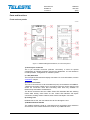
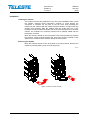
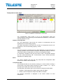
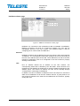
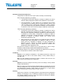
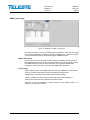
User Manual
HDM100
59300315
Rev.005
14.3.2011
1(54)
HDO Series
User Manual
Teleste Corporation
HDM100
Management Modem
User Manual
HDM100
59300315
Rev.005
14.3.2011
2(54)
Contents
Introduction ........................................................................................................ 3
Parts and functions ........................................................................................... 4
Front and rear panels .......................................................................................... 4
Installation ............................................................................................................ 6
Indicators ............................................................................................................. 7
Software .............................................................................................................. 8
Establishing connection ....................................................................................... 8
Alarms .................................................................................................................. 9
HDM100 T viewer pages .................................................................................. 10
Status viewer page ............................................................................................ 11
HFC Devices viewer page ................................................................................. 12
Modem viewer page .......................................................................................... 16
Settings viewer page ......................................................................................... 18
Interfaces viewer page....................................................................................... 21
Monitoring viewer page ..................................................................................... 23
Properties viewer page ...................................................................................... 27
HDM100 H viewer pages ................................................................................. 28
Status viewer page ............................................................................................ 29
Transponders viewer page ................................................................................ 30
Modem viewer page .......................................................................................... 33
Settings viewer page ......................................................................................... 34
Interfaces viewer page....................................................................................... 36
SNMP viewer page ............................................................................................ 39
NTP viewer page ............................................................................................... 41
Monitoring viewer page ..................................................................................... 42
Properties viewer page ...................................................................................... 46
Legal declarations ........................................................................................... 47
Appendixes ...................................................................................................... 48
Appendix A: HDM100 T routing and IP address settings .................................. 48
Appendix B: Communication trouble-shooter .................................................... 51
Appendix C: IP addresses in CATVisor ............................................................. 52
Appendix D: Transponder registration procedure flowchart for HDM100 T ...... 54
User Manual
HDM100
59300315
Rev.005
14.3.2011
3(54)
Introduction
HDM100 is a management modem in HDO mechanics. It communicates with
transponders via its RF modem, maintains a list of transponder statuses,
manages the MAC data link and provides IP connectivity between management
software and transponders.
HDM100 T supports Teleste transponders using Teleste CATVisor protocol.
HDM100 H supports Teleste and also other manufacturers’ transponders using
SCTE HMS protocol.
Whenever this manual mentions "HDM100", it applies to both HDM100 T and
HDM100 H.
User Manual
HDM100
59300315
Rev.005
14.3.2011
4(54)
Parts and functions
Front and rear panels
7911043
Figure 1. HDM100 Management Modem, front and rear panels
1) Service port connector
The 6 pin mini-DIN connector (RS-232 connection) is used for special
configuration by Teleste production and service department. It is not needed in
normal operation, configuration or software update.
2, 3 & 4) Indicators
The front panel LED indicators display unit status. For more information, see the
"Indicators" chapter.
5) Ethernet connector
The unit is connected to Local Area Network (LAN) via a standard 10/100BaseT Ethernet connection. Either front or rear panel connector can be used for LAN
and/or PC connection. Note that connecting them both may establish an
Ethernet loop and lead to misbehaviour.
The RJ-45 connectors have two LEDs. Green LED indicates data link, blinking
means data activity, dark means no link. Yellow LED indicates full duplex
connection, blinking means collisions, dark means half duplex connection.
6) Cooling vent
HDM100 has no fan; this vent allows free air flow through the unit.
7) Module extractor handle
The module extractor handle is a mechanical lever that allows easy extraction
and removal of the module without the need for any additional tools.
User Manual
HDM100
59300315
Rev.005
14.3.2011
5(54)
8) Module data and power connector
The D-9 connector on the rear of the module connects to the installation frame
and provides powering and HDO bus data link to the unit.
9) Ethernet connector
The unit is connected to Local Area Network (LAN) via a standard 10/100BaseT Ethernet connection. Either front or rear panel connector can be used for LAN
and/or PC connection. Note that connecting them both may establish an
Ethernet loop and lead to misbehaviour.
The RJ-45 connectors have two LEDs. Green LED indicates data link, blinking
means data activity, dark means no link. Yellow LED indicates full duplex
connection, blinking means collisions, dark means half duplex connection.
10) RF input connector
RF input connector (F female) is located on the bottom right corner of the rear
panel.
11) RF output connector
The RF output connector (F female) is located on the bottom left corner of the
rear panel.
User Manual
HDM100
59300315
Rev.005
14.3.2011
6(54)
Installation
Installing the module
The module can be freely positioned in any slot in the installation frame. Install
the module, following these instructions carefully to avoid denting the
connectors or surfaces. Do not push on the fan cover when installing the
module into the chassis. With the module extractor handle in its right-hand stop
position (eject position) slide the module along the guide rails into a slot,
pushing it in until the extractor handle rest on the latch rail extrusion of the HDX
chassis. The module’s D-9 connector should now be partially mated with the
back plane connector.
Move the extractor handle on the front panel to the closed position by pressing
the extractor handle inwards towards the front panel until the module is fully
seated in the chassis and the extractor handle locks into place.
Removing the module
Move the extractor handle on the front panel to the eject position. Remove the
module by carefully pulling it out of its slot (Figure 2).
7905110
2
1
Figure 2. Removal of the module.
User Manual
HDM100
59300315
Rev.005
14.3.2011
7(54)
Indicators
The unit has three LEDs on the front panel labelled as TRANSMITTER (Tx),
RECEIVER (Rx) and MODULE (M). These LEDs’ colours reflect the unit’s alarm
status, i.e. which alarms are active. RF modem related alarms are indicated
with Rx and Tx LEDs, others with Module LED.
If there are one or more “Major” alarms, the affected LED will be red. If there are
no “Major” alarms, but one or more “Minor” alarms, the affected LED will be
yellow. If there are no “Major” or “Minor” alarms, the LED will be green. Note
that the “Notification” alarms are not indicated by LEDs.
During the power-up sequence all three LEDs are yellow.
Module LED blinks when configuration session (viewer) is open to the module.
All LEDs blink simultaneously in red if application software cannot start.
See the "Alarms" chapter for details on alarms and LED usage.
User Manual
HDM100
59300315
Rev.005
14.3.2011
8(54)
Software
Establishing connection
Teleste CATVisor Commander connection (both HDM100 T and HDM100 H)
All the needed configurations and adjustments can be carried out locally or
remotely by the CATVisor Commander software. The connection to HDM100 is
possible using the following methods, listed in order of preference:
Remote IP connection through 10/100Base-T Ethernet. “IP Gateway”
connection type should be used to open a tree view of HDM100 and the
transponders connected to it. “Direct IP” connection type should be used if there
is no need to see the transponders in a tree view.
The HDM’s Ethernet port IP address and net mask have to be set locally
through “Interfaces” page before this can be used.
Local DVX bus connection between the management bus connector of the
HDX installation frame and serial port of a PC using DVX021 cable (DVX bus /
19200 bps). Note: The local bus connection cannot be used to communicate
with HFC transponders and is recommended only for initial setup (IP address
etc) of HDM100. HDM100 software update is not possible via local connection.
Detailed hardware requirements and software installation instructions can be
found from the Commander User Manual supplied with the software.
SNMP connection (HDM100 H only)
All the parameters of the HMS version (HDM100 H) can be accessed and
configured with SNMP through 10/100Base-T Ethernet. The initial setup (IP
addresses, net mask, SNMP communities) have to be set first using CATVisor
Commander.
Remote SNMP connection can be opened with any SNMP browser, or with
Teleste CATVisor Commander using “SNMP element” connection type. It is
however not possible to open a tree view of the connected transponders in
CATVisor Commander using “SNMP element” connection type, thus "IP
Gateway" connection type is preferred.
rd
The SNMP MIB files for HDM100 to be used with 3 party SNMP browser can
be downloaded from Teleste Club.
User Manual
HDM100
59300315
Rev.005
14.3.2011
9(54)
Alarms
All module alarms (="flags") displayed in CATVisor Commander and EMS with
affected LED and factory default severity settings are described in the table 1
below.
Alarm severities (Major / Minor / Notification / Disabled) and alarm limits can be
configured by the user. See the "Monitoring" chapter for more details.
Alarm text
Internal error
Settings changed
Application started
Temperature high
Temperature low
IP address conflict
Transponder IP
address conflict
RF modem
transmitter off
No HFC devices
connected
Description & suggested corrective action
Internal error in unit prevents normal operation. If
resetting the unit doesn’t help, contact Teleste
support.
Unit's settings have been modified by user during
last minute.
Unit was reset or rebooted during last minute.
Unit internal temperature is above high limit. Check
ambient temperature and adjust if necessary.
Unit internal temperature is below low limit. Check
ambient temperature and adjust if necessary.
HDM’s own IP addresses or gateway not set or
conflicting with each other. Check and adjust if
necessary.
Transponder IP addresses are not within HDM's
net mask or duplicate IP addresses are found.
RF modem transmitter is turned off by user, or unit
is in slave mode.
There are no devices in transponder list.
Table 1. HDM100 Alarms
LED
Factory
default
severity
M
Major
M
Notification
M
Notification
M
Major & Minor
M
Major
M
Notification
M
Minor
Tx
Notification
Rx
Minor
User Manual
HDM100
59300315
Rev.005
14.3.2011
10(54)
HDM100 T VIEWER PAGES
This chapter presents HDM100 T viewer pages using local “DVX bus”
connection type or remote “Direct IP” / “IP Gateway” connection types.
HDM100 T viewer pages in CATVisor Commander / EMS:
−
−
−
−
−
−
−
Status
HFC Devices
Modem
Settings
Interfaces
Monitoring
Properties
Some viewer pages have fields with coloured background. These colours
indicate the alarms related to this field. Green means no alarms or notifications;
red is major alarm, yellow is minor alarm and blue is notification.
User Manual
HDM100
59300315
Rev.005
14.3.2011
11(54)
Status viewer page
Figure 3. HDM100 T "Status" viewer page
The “Status” page shows unit’s present status and possible alarms / warnings /
notifications (= “flags”). Each alarm is colour coded according to its severity. For
additional information about alarms, see the Alarms chapter.
It is possible to hide the less critical alarms by checking the corresponding
check box for warnings and/or notifications.
User Manual
HDM100
59300315
Rev.005
14.3.2011
12(54)
HFC Devices viewer page
Figure 4. HDM100 T "HFC Devices" viewer page
The “HFC Devices” page shows a list of all transponders communicating with
HDM100 T.
The number of connected devices is displayed in the “Number of devices” field.
The background of this field is yellow if there are no HFC devices connected,
otherwise green. The list status is displayed in the accompanying field:
•
“Initializing…” yellow background: preliminary data is being read.
•
“Reading…” yellow background: device list is being read.
•
“Ready”, green background: device list is complete.
•
“TIMEOUTED!” red background: Error occurred while in reading the device
list. Clicking “Refresh” should help if connection to HDM100 T is OK.
HFC poll round time
The “HFC poll round time” indicates the time it takes HDM100 T to poll all
devices and detect changes in transponder statuses. This time varies with
number of transponders and amount of IP traffic.
Device list
The device list can be sorted by clicking on a column header. Clicking a second
time on the same header reverses the order. A small arrow next to the header
text shows the sort direction.
The following information is displayed for each transponder:
for everything OK,
/
/
Status icon: Summary of transponder status.
for IP address conflict, high failure rate, low receive level or saturated transmit
level.
IP Address: The IP address of the transponder. The following invalid IP
addresses are shown on the list with yellow background colour:
•
IP address outside HDM100 T’s HFC subnet, e.g. transponder factory
default address 0.0.0.0.
•
Duplicate IP addresses in two or more transponders.
User Manual
HDM100
59300315
Rev.005
14.3.2011
13(54)
Type: The transponder type.
Name and Location: The "Alias name" and "Location" identification information
read from the transponder when it was registered. Not supported by all devices.
The columns are displayed only with new HDM100 T software versions which
supports them. The data is updated only during registration.
Replies: Counter for replied packets since last transponder registration. This
counter indicates not only the replies to IP packets sent to the device but also
the replies to the routine polling packets regularly sent by HDM100 T.
Failures: Counter for unanswered poll packets. Note that it is common that a
couple of failures are present already when a transponder appears on the list.
This is due to transmit level calibration process in the beginning of normal
communication. The field background colour is yellow if failure-% is over 2 %
and red if it is over 5 %.
Tx (dBµV): Transponder’s transmit level. The following additional information is
displayed:
•
A tilde (~) sign in front of the value: The transmit level displays the
commanded value to the transponder, not the value the transponder is
actually using, and may thus differ from the actual transmit level. When
the enhanced MAC layer is enabled on “Settings” page, and the
transponder supports it, the transmit level value is the actual level used
by the transponder and displayed without the tilde prefix.
•
"Max" or "Min" in front of the value with blue background colour: The
transponder’s level control is either at maximum or minimum.
Rx (dBµV): Indicates the measured RF level at HDM100 T RF input. In a stable
situation (not immediately after registration) with ALC enabled and not
saturated, this should be very close to the target receive level, set in “Modem”
page. If the receive level is below 50 dBµV, the value is displayed with yellow
background colour
MAC address: The transponder’s unique, hard-coded physical address.
Registration time: Displays when the transponder was successfully registered.
Calculated using the PC clock running the viewer.
HW ver: Hardware version of the transponder.
SW ver: Software version of the transponder.
Serial #: Serial number of the transponder.
Changes: A change in this counter value indicates that there has been a
change in transponder alarms (new alarms appeared or old alarms cleared).
The change counter signals the EMS system that the unit should be polled for
detailed alarm information. A regularly changing value indicates one or more
unstable alarms at the transponder.
Second IP: IP address of the 2
nd
communications port of the transponder.
nd
Second mask: Subnet mask of the 2 communications port.
rd
Third IP: IP address of the 3 communications port of the transponder.
rd
Third mask: Subnet mask of the 3 communications port.
The line(s) selected by the user on the list are refreshed at ~1 second interval.
The selected devices are shown with blue background colour.
User Manual
HDM100
59300315
Rev.005
14.3.2011
14(54)
Modify device IP
It is possible that a transponder appears on the device list but communication to
it is not possible. This is most probably due to misconfigured transponder IP
address.
There are two possible transponder IP address configuration problems that can
prevent IP layer communication (e.g. CATVisor Commander and EMS):
• Duplicate IP address in two or more transponders.
• IP address outside HDM100 T’s HFC subnet, e.g. transponder factory
default address 0.0.0.0.
The “Modify device IP” feature can be used to remotely change transponder IP
address, eliminating the need to go on-site for local configuration. It also allows
changing the alias name of the device. Note that the “Modify device IP” feature
is accessible only by users with at least “Service” level user rights.
The new IP address should be unique and match the HDM100 T’s HFC subnet
to ensure proper operation and IP level communication with the HEC. The
“Modify device IP” button is activated when one or several devices are selected
on the list. The selected devices are shown with blue background colour.
Clicking the "Modify device IP" button will open the "Modify IP" dialog:
Figure 5. The Modify IP dialog
The “MAC address” is the transponder’s unique, hard-coded physical address.
It can be used to identify the transponder in cases where the IP address of the
unit is incorrect and thus remote IP connection to the transponder is not
possible.
A progress bar will be displayed at the bottom of the window while transponder
information is read from the HDM100 T. When finished, selected transponders'
MAC addresses and IP addresses are shown. Transponders with identical IP
addresses will be displayed separately. Existing alias names cannot be read,
only writing new ones is possible through the "Modify IP" dialog.
IP addresses and alias names can be changed by clicking on the cell and typing
a new value. The changed values are shown with blue background colour.
The “Automatic IP address” button opens a dialog box where the IP address for
the first device can be entered. Remaining devices are then automatically
assigned consecutive IP addresses in ascending order, making it easier to
assign addresses for a large number of devices.
User Manual
HDM100
59300315
Rev.005
14.3.2011
15(54)
Clicking “Cancel” will undo the changes and restore the original settings.
Clicking "Refresh" will reload the data from transponders. Clicking "Apply" will
start the process of writing the modified (blue) fields to transponders. Only the
fields with changed values will be written to the transponders. Clicking “Close”
will close the dialog and return to “HFC devices” viewer page.
All alias name changes, if any, are processed first. Then each transponder with
changed IP address will be sent a command to change the address and after
that a command to reset itself. A progress bar at the bottom of the window will
be displayed during the writing progress.
If the transponder successfully receives both "Change IP address" and "Reset"
commands, it will disappear from the HFC device list and reappear with the new
IP address within a couple of minutes, depending on network size and
communication settings.
After the device has reappeared on the list with the correct IP address, viewer
connection can be established to identify the device and the device can be
assigned its “final” IP address, if necessary.
Note that sometimes a communication problem can cause a transponder to not
receive HDM100 T’s “Change IP address" and "Reset” command sequence.
This transponder will then naturally continue communication with its old IP
address. The only way to detect whether the transponder has received the
commands or not is to wait for changes in the device list.
Remove device
Clicking the "Remove device" button removes the selected device(s) from the
list. The device(s) then starts scanning for a new communication channel.
Clear table & reregister
The “Clear table & reregister” button clears the HFC device table and
broadcasts re-registration request to all transponders supporting enhanced
MAC layer. This can be useful in debugging transponder communication.
Save
Clicking the “Save” button saves the HDM100 T settings and HFC device list to
a text file. It opens a dialog for entering the filename. If the specified file exists,
the current device list is appended to the file.
Device Information
Double-clicking a device list row opens device information dialog containing the
same information as in device list:
Figure 6. The device information dialog
User Manual
HDM100
59300315
Rev.005
14.3.2011
16(54)
Modem viewer page
Figure 7. HDM100 T "Modem" viewer page
The “Modem” page is used for configuring HDM100 T RF modem functionality.
Transmitter
When the transmitter is disabled, HDM100 T RF output is shut off.
“Frequency” edit box specifies the transmit frequency for the RF modem
between 80…200 MHz in 0.1 MHz steps. The channel bandwidth is 0.4 MHz,
thus multiple HDM100 T carriers should be separated by at least 0.5 MHz.
“Level” edit box specifies the transmit level, allowed values are between
80…105 dBµV. The transmit level should usually be set so that it results in
3...10 dB backoff, i.e. 3...10 dB below analogue TV channel levels.
Receiver
“Frequency” edit box specifies the receive frequency for the RF modem
between 5…65 MHz in 0.1 MHz steps. The channel bandwidth is 0.4 MHz, thus
several HDM100 T carriers should be separated by at least 0.5 MHz.
In some networks it may be necessary to add an attenuator to HDM100 T
receiver input to reduce input level to the dynamic range 50...90 dBµV.
Automatic level control
The HDM100 T measures continuously the RF levels of each data packet it
receives. If ALC is enabled, HDM100 T transmits power controlling commands
to transponders in order to achieve the reference value set in the “Target
receive level” field. The allowed values for this field are 45…80 dBµV, the
dynamic range of the receiver. The correct value for "Target receive level"
depends on the return path nominal level at HDM100 T's RF input, and should
usually be some dBs below the return path payload levels. A good starting
value is 60 dBµV.
HDM100 T will never command any device to transmit with level outside the
range specified in “Commanded transmit level range” fields. The transmit level
is adjusted only if it is off target more than the value specified in the “Hysteresis”
field, default 1 dB. Transponders’ own transmit level range settings override the
commands sent by HDM100 T.
User Manual
HDM100
59300315
Rev.005
14.3.2011
17(54)
Potential problems with the ALC level settings are displayed in the “HFC
Devices” page (Max: or Min: prefix). All devices in the HFC network do not
necessarily support transmit level adjusting commands sent by HDM100 T.
These devices ignore these commands; nevertheless the communication works
properly provided the locally adjusted transmit level is OK.
If ALC is disabled, transponders will transmit using whatever level was used
when they were successfully registered.
Transponders supporting enhanced MAC layer send their RF transmitter level
and saturation information to the HDM100 T. This enhances ALC accuracy. Old
transponders (roughly pre-2005) do not send this information, so the ALC has to
assume the transponder has received the last transmit level command and is
using the commanded level. This can sometimes lead to transponder transmit
level fluctuations in large networks.
User Manual
HDM100
59300315
Rev.005
14.3.2011
18(54)
Settings viewer page
Figure 8. HDM100 T "Settings" viewer page
The “Settings” page is used for configuring HDM100 T RF modem medium
access (MAC) layer functionality. These settings affect transponder registration
and data communication efficiency.
Device acceptance during registration
The “Maximum number of accepted HFC devices” edit box is used to restrict the
number of devices accepted to the device list of HDM100 T. This field can be
used together with device groups to distribute transponders between multiple
HDM100 Ts. The upper limit is 500, but in some cases it may be necessary to
limit the number of transponders per one HDM100 T to less than 200 to achieve
sufficient data throughput.
The “Use enhanced MAC layer” check box should be checked unless
communication errors appear with old transponders. When checked, and the
transponder supports enhanced MAC layer:
• HDM100 T sends device group information at the start of registration
process, speeding up registration in systems equipped with multiple
HDM100 T units.
• HDM100 T sends “Transponder drop timeout” parameter to transponders.
This parameter affects transponder behaviour in large networks.
• Transponders will send their actual used transmit level to HDM100 T,
making the ALC more accurate.
Note that if there are DSM100 subheadend controllers in the network, enhanced
MAC layer must be turned off.
The “Accepted device groups” setting is composed of nine check boxes. These
options can be used to divide devices to more than one HDM100 T in the same
network. For example, if the check box five is selected, only the transponder
devices with device group 5 selected are allowed to register under this HDM100
T unit. The option “All” ignores the device group information of the registered
device and all devices are accepted.
Old transponders not supporting enhanced MAC layer check the device group
setting only at registration. New ones check it also during communication,
User Manual
HDM100
59300315
Rev.005
14.3.2011
19(54)
causing them to immediately reset their modems if HDM100 T device group is
changed on-the-fly.
Refer to Appendix D for more information on the registration procedure.
Network dependent parameters
The “Contention ratio” field defines the percentage of time HDM100 T uses for
allowing new transponders to register. The rest of the time the controller spends
polling registered transponders and managing IP traffic between them and
management system. The ratio can be increased at first and decreased later on
since new devices only need to be registered once. The contention ratio should
be between 5% and 50%, a good start value is 10%.
The “Transponder drop timeout” field defines how long HDM100 T keeps a
transponder on its device list when it hasn’t received replies from it. The default
value is 30 s and it should be increased in large networks to be at least twice
the typical “HFC poll round time” in “HFC Devices” page.
The “Transponder poll timeout” field has effect only if “Use enhanced MAC
layer” is selected. This field defines how long a transponder stays connected to
a HDM100 T without being polled by it. After this time the transponder restarts
the registration process. This parameter is sent to all transponders before the
actual registration. Typical and default time is 100 s, which should be increased
in large networks to be at least twice the typical “HFC poll round time” in “HFC
Devices” page. Value 0 forces the transponders to stay online even if they’re
not polled at all. Only new transponders supporting enhanced MAC layer use
this parameter, old ones simply ignore this setting and use the default 100 s.
Refer to Appendix D (“Timeout 4”) for more information on the registration
procedure.
“Poll count” and “IP count” are for-experts-only parameters that adjust the
balance between polling and IP traffic, thus determining the behaviour of
HDM100 T’s internal transmit queue. The default values, 5 and 2 respectively,
are OK for most networks. “Poll count” specifies how many poll packets are sent
in a row before sending an IP packet, whereas “IP count” specifies how many IP
packets may be sent in a row before sending a poll packet again.
Registration parameters
This frame shows parameters that have influence on the registration procedure
of the devices. These parameters are sent to transponders before the actual
registration. The use of these parameters is intended for an experienced user
only. “Retries per power level” specifies how many times a transponder tries to
register using its current transmit level, starting from its minimum value. “Power
increment” specifies how many dB’s the transmit level is increased after
“Retries per power level” has been reached. “Back-off period” defines the length
of the time window the transponder uses to select a random time to send its
registration request. “ACK timeout” (“Timeout3” in Appendix D) defines how
long the transponder waits for a reply from the HDM100 T before retrying
registration.
Refer to Appendix D for more information on the registration procedure.
User Manual
HDM100
59300315
Rev.005
14.3.2011
20(54)
Reply polling
When a message is sent to a transponder, HDM100 T gives the transponder
some time to process the message and then polls for the device for reply
message after the time defined in “Reply polling Delay”. If the reply is not yet
ready, HDM100 T tries again after the same delay. Total number of attempts for
reply polls is set in the “Reply polling Retries” edit box. The time needed in HFC
network device for handling the message and generating the reply depends on
e.g. the device in question and the message type. The reply polling delay
should be adjusted so that most of the devices can reply in most of the cases
on the first occasion. A good general estimation for this is 100 ms.
User Manual
HDM100
59300315
Rev.005
14.3.2011
21(54)
Interfaces viewer page
Figure 9. HDM100 T "Interfaces" viewer page
HDM100 T is connected to the management LAN via standard 10/100Base-T
Ethernet connection and acts as a data link between the LAN and the
manageable devices in the HFC network. The Interfaces page is used for
configuring the IP router inside the HDM100 T.
Ethernet
HDM100 T needs a free IP address from the LAN, which is then set to Ethernet
“IP address”. The corresponding “Net mask” (subnet) has to be set according to
the size of the address space of the LAN. These addresses, as well as the HFC
network IP addresses, have to be configured to the LAN routers for properly
working communication.
HFC
HFC IP address defines the IP address for the HFC network. The
corresponding subnet size is defined by the “Net mask”. All the transponders to
be registered to this HDM100 T should have a unique IP address belonging to
this address space. Transponder IP address can also be set remotely through
“HFC Devices” viewer page in HDM100 T.
In addition, the HFC IP address of HDM100 T has to be unique too, and hence
differ from IP addresses of all the HFC network devices. A good practice is to
use the last IP address in the subnet for the HDM100 T HFC interface, typically
ending with .254.
IP address
Ethernet: The IP address of HDM100 T. This address should be unique and
consistent with the LAN IP and subnet settings. Factory default setting is
192.168.0.100.
HFC: The HFC interface must have a unique IP address that must be in the
same subnet as all transponder IP addresses.
User Manual
HDM100
59300315
Rev.005
14.3.2011
22(54)
Net mask
Ethernet: Should be configured according to the LAN settings. Factory default
setting is 255.255.255.0.
HFC: The HFC net mask must fit the planned number of transponders that will
connect to HDM100 T. The most typical mask is 255.255.255.0 that can fit up to
254 transponders. However, larger masks can be used e.g. in cases where
groups of transponders are allocated to smaller subnets.
Gateway
Applies only to Ethernet. The default gateway. All packets that have destination
address not belonging to any of HDM100 T subnets are sent to this address.
The gateway address must be in the same subnet as Ethernet IP address.
Factory default setting is 192.168.0.254.
HW address
Applies only to Ethernet. Read-only MAC address of HDM100 T.
Poll round time
Applies only to HFC. Duration of the HFC poll round cycle. This value indicates
the maximum time it takes HDM100 T to detect changes in transponder status.
Received packets
Number of valid IP packets received since reset.
Sent packets
Number of sent IP packets sent since reset.
Bad packets
Number of invalid IP packets detected.
User Manual
HDM100
59300315
Rev.005
14.3.2011
23(54)
Monitoring viewer page
Figure 10. HDM100 T "Monitoring" viewer page
The "Monitoring" page displays HDM100 T's monitored parameters and their
values as well as alarm limits, current statuses and severity settings.
Analog parameters
Each monitored analog parameter of the unit is displayed in the upper half of
the frame with following information in the list:
Analog parameter: Name of the monitored parameter
Alarm: Alarm status of the parameter: No / LO / HI / LOLO / HIHI
Value: Current measured value
HIHI: High major alarm limit
HI: High minor alarm limit
LO: Low minor alarm limit
LOLO: Low major alarm limit
Deadband: Specifies how much the measured value has to be on the "safe"
side of alarm limit before turning off the alarm.
Unit: Unit of the measured parameter
The colour of each list entry and the icon next to parameter name indicate alarm
status:
-
green for nominal value
-
red for major alarm
-
yellow for minor alarm
-
grey for disabled alarm
User Manual
HDM100
59300315
Rev.005
14.3.2011
24(54)
The alarm settings are user configurable by double-clicking an analog
parameter. This opens a dialog box with parameter's alarm limits, enables and
deadband that can be edited by users with at least "Service" level user rights.
For others this is read-only information.
Figure 11 The analog alarm configuration dialog box
Each alarm limit can be individually enabled/disabled and configured. The alarm
limits should be in decreasing order, preferably with more than "Deadband"
units between each limit.
Discrete parameters
Each monitored discrete parameter value is displayed in the lower half of the
frame with following information in the list:
Discrete parameter: Name of the monitored parameter
Alarm: Alarm status of the parameter: No / Notification / Minor / Major. If the
alarm is disabled, but parameter is in alarming state, "Yes" is shown.
Setting: Alarm severity can be configured to Major, Minor, Notification or
Disabled.
The colour of each list entry and the icon next to parameter name indicate alarm
status:
-
green for nominal value
-
red for major alarm
-
yellow for minor alarm
-
blue for notification
-
grey for disabled alarm
User Manual
HDM100
59300315
Rev.005
14.3.2011
25(54)
The alarm severity setting is user configurable by double-clicking a discrete
parameter. This will open a dialog box which can be edited by users with at
least "Service" level user rights. For others this is read-only information.
Figure 12. The discrete alarm configuration dialog box
Alarm control
Alarm control frame provides independent on-delay and off-delay timers. The
time delay feature can be used to eliminate false alarm triggering due to
momentary disturbances. An alarm is only active when “Detection” is enabled
and the monitored parameter has been over limit longer than "Delay On" time.
Alarm goes off when the parameter has been inside limits longer than "Delay
Off" time.
The settings on the “Alarm control” frame can be edited by a user with at least
Service level user rights. For others this is read-only information. It is
recommended not to change these values without fully understanding the
effects on EMS system performance.
User Manual
HDM100
59300315
Rev.005
14.3.2011
26(54)
Alarm log
Clicking "Alarm log" button on "Monitoring" page opens alarm log dialog box.
Figure 13. The Alarm dialog box
The “Alarm log” dialog box displays the alarm history for latest 32 events. The
list is stored in non-volatile memory. All entries are date and time stamped with
the latest entry at the bottom. Note that date/time information is based on PC
clock and HDM100 T uptime and thus may be incorrect for events that occurred
before the latest reset for HDM100 T.
The colour of each list entry and the icon next to parameter name indicate alarm
status:
-
green for nominal value
-
red for a major alarm
-
yellow for a minor alarm
-
blue for a notification
Total number of entries in the alarm log list is shown in the “Number of entries”
field. The index number of the last entry is displayed in the accompanying field.
Total number of entries is limited to 32. The oldest entry is overwritten when the
log is full.
To update “Alarm log” page, click the “Refresh” button.
The “Clear and regenerate log” button empties the alarm log and restarts alarm
detection.
User Manual
HDM100
59300315
Rev.005
14.3.2011
27(54)
Properties viewer page
Figure 14. HDM100 T "Properties" viewer page
The Properties page displays module identification and statistics data.
Identification
The user can enter a descriptive alias name for the station into the “Name” field,
such as site location etc. Alias name can contain up to 63 alphanumeric
characters.
The type, serial number and hardware version of the module as well as the
software version are read-only information.
Statistics
HDM100 T installation position is shown in the "Position" field as “Rack” and
“Slot” numbers.
The “Uptime” field shows the time since the last reset / power up. The format is
days, hours, minutes and seconds.
The "Total uptime" field shows the total number of full operating days of the unit.
The "Reset count" field shows the total number of unit resets.
User Manual
HDM100
59300315
Rev.005
14.3.2011
28(54)
HDM100 H VIEWER PAGES
This chapter presents HDM100 H viewer pages using local “DVX bus”
connection type or remote “Direct IP” / “IP Gateway” connection types. The
viewer pages of HDM100 H when using “SNMP element” connection type are
slightly different in layout but contain basically the same parameters.
HDM100 H viewer pages in CATVisor Commander / EMS:
−
−
−
−
−
−
−
−
−
Status
Transponders
Modem
Settings
Interfaces
SNMP
NTP
Monitoring
Properties
Some viewer pages have fields with coloured background. These colours
indicate the alarms related to this field. Green means no alarms or notifications;
red is major alarm, yellow is minor alarm and blue is notification.
User Manual
HDM100
59300315
Rev.005
14.3.2011
29(54)
Status viewer page
Figure 15. HDM100 H "Status" viewer page
The “Status” page shows unit’s present status and possible alarms / warnings /
notifications (= “flags”). Each status flag is colour coded according to its
severity. For additional information about status flags, see table of module flag
descriptions in the Alarms chapter.
It is possible to hide the less critical flags by checking the corresponding check
box for warnings and/or notifications.
User Manual
HDM100
59300315
Rev.005
14.3.2011
30(54)
Transponders viewer page
Figure 16. HDM100 H "Transponders" viewer page
The “Transponders” page shows a list of all transponders which are
communicating or have previously communicated with HDM100 H or have been
manually added to the list.
Number of transponders
The “OK transponders” field shows the number of transponders that are
registered and communicating properly.
The “Bad transponders” field shows the number of transponders that are not
registered, or not communicating properly, or both.
Poll round time
The “Poll round time” indicates the time it takes HDM100 H to poll all devices in
“Polling” operation mode and detect changes in transponder statuses. This time
varies with number of transponders and amount of management traffic.
In “Contention” operation mode poll round time is “N/A”. Transponder statuses
are then polled periodically with “Communication check” interval parameter
adjustable via "Settings" page.
Show
The “Show” selection (All, Only OK, Only bad) filters the transponder table
based on the status of the transponder.
Transponder table
The transponder table can be sorted by clicking on a column header. Clicking a
second time on the same header reverses the order. A small “+” or “-“ sign to
the right of the header text shows the sort direction.
The data field in the bottom right corner shows the transponder table status:
•
“Reading”, yellow background: data is being read from HDM.
•
“Ready”, green background: transponder table is complete.
The following information is displayed in the column header for each
transponder:
User Manual
HDM100
59300315
Rev.005
14.3.2011
31(54)
Status icon: Summary of transponder status.
green for everything OK,
/
/
for transponder not communicating, not registered, IP address conflict,
high failure rate or low receive level.
Comm. status: “OK” for no errors, or abbreviation of the error code. Doubleclicking the row opens a dialog for more details.
Registered: Transponder registration
transponders are allowed to send traps.
status
(yes/no).
Only
registered
Alarms: Transponder’s alarm status. “Major” if transponder has at least 1 major
alarm, “Minor” if transponder has no major alarms but at least 1 minor alarm,
“No” if transponder has no alarms.
MAC: The transponder’s unique, hard-coded identification code.
IP address: The IP address of the transponder.
The following invalid IP addresses are shown on the list with yellow background
colour:
•
IP address outside HDM100 T’s HFC subnet, e.g. transponder factory
default address 0.0.0.0.
•
Duplicate IP addresses in two or more transponders.
Queries: Total number of unicast packets sent to transponder.
Failures: Total number of missing replies to unicast packets sent to
transponder, and the failures/queries ratio.
Contiguous failures: Number of consecutive missing replies to unicast packets
sent to transponder. This value is reset to zero when a reply is received.
Rx (dBµV): Indicates the measured receive RF level at HDM100 H RF input. If
the level is below 50 dBµV, the value is displayed with yellow background
colour.
Last status change time: Time when transponder status was last changed.
Last response time: Time when last reply was received from transponder.
Registration time: Time when the transponder was registered.
The transponder IP address can be edited by either double-clicking a row in
transponder table or selecting a row and then clicking “Edit” button. This will
open a dialog box with transponder's properties.
User Manual
HDM100
59300315
Rev.005
14.3.2011
32(54)
Figure 17. The Edit transponder dialog
Add
A new transponder can be entered manually into the system in e.g. cases
where the transponder is not yet installed. Clicking “Add” button opens a dialog
box with the new transponder’s IP address and MAC address.
Figure 18. The Add transponder dialog
Remove
Clicking the "Remove" button removes the selected transponders from the
table.
Copy table to clipboard
“Copy table to clipboard” button copies all information on the “Transponders"
page onto the clipboard. This can e.g. be pasted to an email when contacting
Teleste support.
User Manual
HDM100
59300315
Rev.005
14.3.2011
33(54)
Modem viewer page
Figure 19. HDM100 H "Modem" viewer page
The “Modem” page is used for configuring HDM100 H RF modem functionality.
Transmitter
When the transmitter is disabled, HDM100 H's RF output is shut off.
“Frequency” edit box specifies the transmit frequency for the RF modem
between 80…200 MHz in 0.1 MHz steps. The channel bandwidth is 0.4 MHz,
thus several HDM100 H carriers should be separated by at least 0.5 MHz.
“Level” edit box specifies the transmit level, allowed values are between
80…105 dBµV. The transmit level should usually be set so that it results in
3...10 dB backoff, i.e. 3...10 dB below analog TV channel levels.
Receiver
“Frequency” edit box specifies the receive frequency for the RF modem
between 5…65 MHz in 0.1 MHz steps. The channel bandwidth is 0.4 MHz, thus
several HDM100 H carriers should be separated by at least 0.5 MHz.
The mute level, i.e. receive level below which the receiver won't work can be
fine-tuned if needed. Usually the factory value 40 dBµV shouldn't be altered.
The number of MAC layer CRC and frame errors is shown in respective fields.
In some networks it may be necessary to add an attenuator to HDM100 H
receiver input to reduce input level to the dynamic range 50...90 dBµV.
Note that HMS standards do not specify automatic level control of return path
data channel, thus transponders communicating with HDM100 H need to have
their transmit levels adjusted manually.
User Manual
HDM100
59300315
Rev.005
14.3.2011
34(54)
Settings viewer page
Figure 20. HDM100 H "Settings" viewer page
The “Settings” page is used for configuring HDM100 H RF modem medium
access (MAC) layer functionality. These settings affect transponder registration
and data communication efficiency.
Operation
This setting defines the operation mode of HDM100 H:
• Polling: HDM100 H uses polling to determine if the device has an alarm
and thus also checks for transponder presence, but alarms are usually
received slower. This is the recommended operation mode.
• Contention: HDM100 H uses broadcast contention mode to be notified
asynchronously about an alarm. Transponders are not polled, and their
presence is checked in longer intervals, but alarms are usually received
faster.
Broadcast intervals
These parameters specify how often HDM100 H sends communication
parameters to transponders.
"Channel descriptor": Interval between the broadcasting of the CHNLDESC
packets. When scanning, transponders use this packet to declare that the
carrier is a valid HMS carrier. The default value 30 s should only be adjusted
together with transponders' respective setting.
"Registration": Interval between the registration periods. Increasing the default
value 60 s may slightly increase data throughput, but transponder registration is
slower.
"Time sync": Interval between the broadcasting of the time synchronisation
packets. HDM100 H starts broadcasting this packet after it has first
synchronised its own clock via NTP. Default value is 600 s.
Contention mode only parameters:
"Broadcast interval": The interval between allowing the transponders to
transmit on contention mode.
"Communication check interval": This is the maximum amount of time the
HDM100 H will allow to pass before automatically attempting communication
to see if the device is still responding.
User Manual
HDM100
59300315
Rev.005
14.3.2011
35(54)
Communication timeouts
These parameters specify how fast HDM100 H expects the transponders to
answer.
"MAC commands": This is the timeout of all MAC packets except the TALK
packet.
"SNMP commands": This is how long the HDM100 H will wait before timing out
a SNMP request. The HDM100 H will not retry SNMP requests.
"Not responding threshold": The number of non-answered queries before the
transponder is declared as "not responding".
"Talk": This is the timeout of the TALK packet.
"MAC broadcast delay": This is the delay after sending a broadcast MAC packet
to transponders.
SNMP broadcast delay: This is the amount of time that the HDM100 H will wait
after multicasting or broadcasting an SNMP request. This applies both to
multicast/broadcast SNMP requests generated by the HMTS itself and to
multicast/broadcast SNMP requests generated by an external SNMP manager.
Registration window
HDM100 H automatically adjusts the transponder registration window length so
that transponders are registered as quickly as possible. Registration window is
lengthened if a large number of transponders trying to register is detected
during the previous registration window.
Min length: This is the minimum and default time for the registration window to
be open.
Max length: This is the maximum time for the registration window to be open.
User Manual
HDM100
59300315
Rev.005
14.3.2011
36(54)
Interfaces viewer page
Figure 21. HDM100 H "Interfaces" viewer page
HDM100 H is connected to the management LAN via standard 10/100Base-T
Ethernet connection and acts as a data link between the LAN and the
manageable devices in the HFC network. The Interfaces page is used for
configuring the IP router inside the HDM100 H.
Ethernet
HDM100 H needs a free IP address from the LAN, which is then set to Ethernet
“IP address”. The corresponding “Net mask” (subnet) has to be set according to
the size of the address space of the LAN. These addresses, as well as the HFC
network IP addresses, have to be configured to the LAN routers for properly
working communication.
HFC
HFC IP address defines the IP address for the HFC network. The
corresponding subnet size is defined by the “Net mask”. All the devices to be
registered to this HDM100 H should have a unique IP address belonging to this
address space. HFC device IP address can also be set remotely through
"Transponders" viewer page in HDM100 H.
In addition, the HFC IP address of HDM100 H has to be unique too, and hence
differ from IP addresses of all the HFC network devices. A good practice is to
use the last IP address in the subnet for the HDM100 H HFC interface, typically
ending with .254.
User Manual
HDM100
59300315
Rev.005
14.3.2011
37(54)
Automatic transponder addressing
Transponder IP addresses can be given either manually or automatically.
When automatic addressing is enabled:
•
Transponders whose MAC address is already in HDM100 H's device
table are always assigned IP address from HDM100 H’s device table.
•
New transponders (i.e. MAC address not in HDM100's device table)
are assigned new IP address from the range specified in “Min IP” and
“Max IP” fields except if transponder already has a valid IP address
(i.e. in HFC subnet and not a duplicate IP address), then transponder’s
IP address is used. New entries are added to HDM100 H device table.
When automatic addressing is disabled:
•
Transponders whose MAC address is already in HDM100 H's device
table are accepted only if transponder’s IP address is valid (i.e. in HFC
subnet and not a duplicate IP address; regardless of what IP address is
in HDM100 H’s device table). Transponder’s IP address is added to
HDM100 H device table. All other transponder IP addresses (0.0.0.0,
duplicate IP address, IP address outside HFC subnet) cause
transponder registration to fail.
•
New transponders (i.e. MAC address not in HDM100's device table) are
accepted only when transponder’s IP address is valid (i.e. in HFC
subnet and not a duplicate IP address). All other transponder IP
addresses (0.0.0.0, duplicate IP address, IP address outside HFC
subnet, HDM100 H device table has different IP address than
transponder) cause registration to fail.
Note that HFC interface IP address may not be within Min IP...Max IP range,
and Min IP...Max IP range must be within HDM100 H HFC subnet.
If a duplicate address or an address not belonging to HDM100 H HFC subnet is
found, "Transponder IP address conflict" alarm is given.
IP address
Ethernet: The IP address of HDM100 H. This address should be unique and
consistent with the LAN IP and subnet settings. Factory default setting is
192.168.0.100.
HFC: The HFC interface must have a unique IP address that must be in the
same subnet as all transponder IP addresses.
Net mask
Ethernet: Should be configured according to the LAN settings. Factory default
setting is 255.255.255.0.
HFC: The HFC net mask must fit the planned number of transponders that will
connect to HDM100 H. The most typical mask is 255.255.255.0 that can fit up to
254 transponders. However, larger masks can be used e.g. in cases where
groups of transponders are allocated to smaller subnets.
Gateway
Applies only to Ethernet. The default gateway. All packets that have destination
address not belonging to any of HDM100 H subnets are sent to this address.
The gateway address must be in the same subnet as Ethernet IP address.
Factory default setting is 192.168.0.254.
User Manual
HDM100
59300315
Rev.005
14.3.2011
38(54)
HW address
Applies only to Ethernet. Read-only MAC address of HDM100 H.
Poll round time
Applies only to HFC. Duration of the HFC poll round cycle. This value indicates
the maximum time it takes HDM100 H to detect changes in transponder status.
This field is relevant only in "Polling" operation mode.
Received packets
Number of valid packets received since reset.
Sent packets
Number of packets sent since reset.
Bad packets
Number of invalid packets detected.
User Manual
HDM100
59300315
Rev.005
14.3.2011
39(54)
SNMP viewer page
Figure 22. HDM100 H "SNMP" viewer page
This page is used to control the SNMP agent parameters. Note that this page
only contains parameters needed for setting up SNMP agent. There are number
of other parameters that are accessible using the SNMP protocol.
SNMP communities
Community names are the weak security method of SNMPv1 to limit access to
the manageable objects. These must match with the community names used by
the SNMP manager. Read or write community is accepted for SNMP GET
operations, write community is accepted for SNMP SET operations.
Trap settings
These settings control how SNMP traps are sent from HDM100 H's own alarms.
They do not affect forwarding of traps received from transponders.
"Enable traps" checkbox is the master switch for trap sending.
"Delay" specifies how long a trap is held in trap queue before sending it.
"Interval" is the minimum time between successive traps.
"Lifetime" is the time HDM100 H keeps the trap in the transmit queue, if it
cannot be sent for some reason.
User Manual
HDM100
59300315
Rev.005
14.3.2011
40(54)
Trap receiver settings
The trap receiver table contains the settings for where SNMP traps from
transponders or HDM100 H alarms are sent. “Edit receiver” button or double
clicking a row opens "Edit trap receiver" dialog.
Figure 23. Edit trap receiver dialog.
IP address: IP address of the SNMP manager receiving traps.
UDP port: Trap UDP port number. Default port is the standard trap port 162.
Community string: Community string for the trap receiver.
“Remove receiver” button clears selected trap receiver by settings IP address
to 0.0.0.0. UDP port and community string are left untouched.
User Manual
HDM100
59300315
Rev.005
14.3.2011
41(54)
NTP viewer page
Figure 24. HDM100 H "NTP" viewer page.
NTP or Network Time Protocol is a protocol designed to synchronize the clocks
of many computers over a network. HDM100 H needs the real time for e.g. time
stamping the SNMP traps. Therefore the time must be set each time the device
is rebooted, either via NTP or manually.
NTP server IP
IP address of the NTP server that HDM100 H uses.
Enable NTP client
If this checkbox is cleared, HDM100 H real time has to be set manually.
Sync interval
Specifies in seconds how often HDM100 H synchronizes its time from NTP
server.
Current time
HDM100 H’s current time.
Time zone
Time zone where HDM100 H is located can be selected from list. This time
zone information is used to get offset from UTC and to switch to summer time
and back.
Synchronise now
"Synchronize now" button forces the HDM100 H to synchronize its time
immediately from NTP server.
Set time
“Set time” button sets HDM100 H time manually based on the “Set time” date
and time fields.
User Manual
HDM100
59300315
Rev.005
14.3.2011
42(54)
Monitoring viewer page
Figure 25. HDM100 H "Monitoring" viewer page
The "Monitoring" page displays monitored parameters and their values as well
as alarm limits, current statuses and severity settings.
Analog parameters
Each monitored analog parameter of the unit is displayed in the upper half of
the frame with following information in the list:
Analog parameter: Name of the monitored parameter
Alarm: Alarm status of the parameter: No / LO / HI / LOLO / HIHI
Value: Current measured value
HIHI: High major alarm limit
HI: High minor alarm limit
LO: Low minor alarm limit
LOLO: Low major alarm limit
Deadband: Specifies how much the measured value has to be on the "safe"
side of alarm limit before turning off the alarm.
Unit: Unit of the measured parameter
The colour of each list entry and the icon next to parameter name indicate alarm
status:
-
green for nominal value
-
red for major alarm
-
yellow for minor alarm
-
grey for disabled alarm
User Manual
HDM100
59300315
Rev.005
14.3.2011
43(54)
The alarm settings are user configurable by double-clicking an analog
parameter. This opens a dialog box with parameter's alarm limits and deadband
that can be edited by users with at least "Service" level user rights. For others
this is read-only information.
Figure 26. The analog alarm configuration dialog box
Each alarm limit can be individually enabled/disabled and configured. The alarm
limits should be in decreasing order, preferably with more than "Deadband"
units between each limit.
Discrete parameters
Each monitored discrete parameter value is displayed in the lower half of the
frame with following information in the list:
Discrete parameter: Name of the monitored parameter
Alarm: Alarm status of the parameter: No / Notification / Minor / Major. If the
alarm is disabled, but parameter is in alarming state, "Yes" is shown.
Setting: Alarm severity can be configured to Major, Minor, Notification or
Disabled.
The colour of each list entry and the icon next to parameter name indicate alarm
status:
-
green for nominal value
-
red for major alarm
-
yellow for minor alarm
-
blue for notification
-
grey for disabled alarm
User Manual
HDM100
59300315
Rev.005
14.3.2011
44(54)
The alarm severity setting is user configurable by double-clicking a discrete
parameter. This will open a dialog box which can be edited by users with at
least "Service" level user rights. For others this is read-only information.
Figure 27. The discrete alarm configuration dialog box
Alarm control
Alarm control frame provides independent on-delay and off-delay timers. The
time delay feature can be used to eliminate false alarm triggering due to
momentary disturbances. An alarm is only active when “Detection” is enabled
and the monitored parameter has been over limit longer than "Delay On" time.
Alarm goes off when the parameter has been inside limits longer than "Delay
Off" time.
The settings on the “Alarm control” frame can be edited by a user with at least
Service level user rights. For others this is read-only information. It is
recommended not to change these values without fully understanding the
effects on EMS system performance.
User Manual
HDM100
59300315
Rev.005
14.3.2011
45(54)
Alarm log
Clicking "Alarm log" button on "Monitoring" page opens alarm log dialog box.
Figure 28. The Alarm dialog box
The “Alarm log” dialog box displays the alarm history for latest 32 events. The
list is stored in non-volatile memory. All entries are date and time stamped with
the latest entry at the bottom. Note that date/time information may not be
correct for events that occurred before the real time clock was set for HDM100
H.
The colour of each list entry and the icon next to parameter name indicate alarm
status:
-
green for nominal value
-
red for a major alarm
-
yellow for a minor alarm
-
blue for a notification
Total number of entries in the alarm log list is shown in the “Number of entries”
field. The index number of the last entry is displayed in the accompanying field.
Total number of entries is limited to 32. The oldest entry is overwritten when the
log is full.
To update “Alarm log” page, click the “Refresh” button.
The “Clear and regenerate log” button empties the alarm log and restarts alarm
detection.
User Manual
HDM100
59300315
Rev.005
14.3.2011
46(54)
Properties viewer page
Figure 29. HDM100 H "Properties" viewer page
The Properties page displays module identification and statistics data.
Identification
The user can enter a descriptive alias name for the station into the “Name” field.
The “Location” and “Contact” fields can be used to store additional information.
These fields accept up to 63 alphanumeric characters.
Operating mode: Read only information identifying that device is HMS version.
The type, serial number and hardware version of the module as well as the
software version are read-only information.
Statistics
HDM100 installation position is shown in the "Position" field as “Rack” and “Slot”
numbers.
The “Uptime” field shows the time since the last reset / power up. The format is
days, hours, minutes and seconds.
The "Total uptime" field shows the total number of full operating days of the unit.
The "Reset count" field shows the total number of unit resets.
Save configuration
“Save configuration” button saves all HDM100 H settings to file. After settings
are gathered from device, Save As dialog appears. This file can then e.g. be
inserted to an email message when contacting Teleste support.
Reboot device
“Reboot device” button sends software reset request to HDM100 H. Same
functionality as Tools -> Send SW reset.
User Manual
HDM100
59300315
Rev.005
14.3.2011
47(54)
Legal declarations
Copyright © 2008 – 2011 Teleste Corporation. All rights reserved.
Teleste is a registered trademark of Teleste Corporation. Other product and
service marks are property of their respective owners.
This document is protected by copyright laws. Unauthorized distribution or
reproduction of this document is strictly prohibited.
Teleste reserves the right to make changes to any of the products described in
this document without notice and all specifications are subject to change without
notice. Current product specifications are stated in the latest versions of
detailed product specifications.
To the maximum extent permitted by applicable law, under no circumstances
shall Teleste be responsible for any loss of data or income or any special,
incidental, consequential or indirect damages howsoever caused.
The contents of this document are provided "as is". Except as required by
applicable law, no warranties of any kind, either express or implied, including,
but not limited to, the implied warranties of merchantability and fitness for a
particular purpose, are made in relation to the accuracy, reliability or contents of
this document.
Teleste reserves the right to revise this document or withdraw it at any time
without notice.
WEEE Notice
This product complies with the relevant clauses of the European
Directive 2002/96/EC on Waste Electrical and Electronic Equipment
(WEEE). The unit must be recycled or discarded according to
applicable local and national regulations.
European Conformity
This equipment conforms to all applicable regulations and directives
of European Union which concern it and has gone through relevant
conformity assessment procedures.
Teleste Corporation
P.O. Box 323
FI-20101 Turku
FINLAND
www.teleste.com
User Manual
HDM100
59300315
Rev.005
14.3.2011
48(54)
APPENDIXES
Appendix A: HDM100 T routing and IP address settings
The purpose of this application note is to clarify the functionality and principles
of HFC Management Modem’s routing and IP address settings.
How HDM100 T routes IP packets
All the packets that HDM100 T receives go to its internal router (Figure 30). The
router has three interfaces:
1. Ethernet, real IP network
2. HFC, real IP network
3. HDM100 T’s own application message handler
Notice: these interfaces are not exactly the same as the physical ports of the
HDM100 T.
HDM100 T IPaddresses
-HFC
-ethernet
Ethernet
-IP addr
-netmask
-GW addr
Router
Application
Interface
HFC
-IP addr
-netmask
-GW addr
Figure 30. HDM100 T router engine
User Manual
HDM100
59300315
Rev.005
14.3.2011
49(54)
The packet always comes from one of these three interfaces and is always
routed to one of the other two interfaces. The decision where to route is based
on the destination IP address (DIPA) of the packet. The decision-making
algorithm is described below. The algorithm stops immediately after the packet
is routed somewhere.
1. If the DIPA is one of the HDM100 T’s interface IP addresses (Ethernet or
HFC interface), the packet is sent to HDM100 T’s application interface.
2. If the DIPA belongs to one of the IP sub network address spaces (Ethernet
or HFC), the packet is routed to the interface in question. Notice: the sub
network address space is defined by the IP address and the net mask.
3. If the DIPA belongs to an IP sub network address space behind any of the
network elements in the HFC network, the packet is routed to the HFC
1
interface (and sent to the router network element in question).
4. IP packets with any other DIPA are always routed to the default gateway
except packets from Ethernet interface which are discarded.
How to configure network addresses
The viewer’s page Interfaces is for configuring the IP router inside the HDM100
T.
There are two real IP interfaces: "Ethernet" (LAN) and the HFC Network.
HDM100 T needs a free IP address from the LAN, which is then set to the
Ethernet IP address. The corresponding net mask has to be set according to
the size of the address space of the LAN.
•
HFC IP address and net mask define an IP address space for the HFC
network. All the devices to register to this HDM100 T must have a locally
configured unique IP address belonging to this address space. In addition,
the HDM100 T’s own HFC IP address has to be unique too, and different
from IP addresses of all the HFC network devices.
•
A default gateway can be defined only to the Ethernet interface. If HDM100
T doesn’t know where to send the packet it uses default gateway. Usually
the default gateway should be a router in the LAN, and this gateway should
be preferred.
The LAN has to be configured so that addresses of all the IP sub networks
under the HDM100 T use the HDM100 T as gateway.
1
In the HFC network, some of the network elements can be routers. It means that they have multiple interfaces
and thus can have one or more IP sub networks behind them (for instance DSM100). HDM100 T gets information
about these networks in the transponder registration process. These sub network addresses and net masks can
nd
nd
rd
rd
be seen in 'HFC Network page using (’2 IP address’, ’2 net mask’, ’3 IP address’ and ’3 net mask’).
User Manual
HDM100
59300315
Rev.005
14.3.2011
50(54)
A simple case example:
A laptop running Commander is connected directly to HDM100 T’s Ethernet
port. HDM100 T addresses are defined as shown in figure below.
Add the route to the laptop by typing the following command in Windows
command prompt:
C:\>route ADD 10.244.32.0 MASK 255.255.248.0 10.10.1.2
The HFC subnet
address
The HFC subnet
mask
HDM100 T’s Ethernet
address as gateway
User Manual
HDM100
59300315
Rev.005
14.3.2011
51(54)
Appendix B: Communication trouble-shooter
EMS Server
Commander
PC-HDM100 T
Communication
Ethernet
HDO
HDM100 T HFC
Network Controller
IP over RF
HDM100 T-Transponder
Communication
DSM100
Subheadend
Controller
DVO/HDO
AC/EMT
BXX
Commander
Figure 31. PC-HDM100 T communication
Investigating HFC Communication (PC - HDM100 T)
1. Ping the IP address of the transponder
Succeeds:
Communication works; Run the Commander with direct
IP-connection to check the quality of service.
Fails:
Go to step 2.
2. Ping the Ethernet address of the HDM100 T
Succeeds:
Go to step 3.
Fails:
Wrong Ethernet address or routing missing in LAN.
3. Ping the HFC address of the HDM100 T
Succeeds:
Continue by investigating the HDM100 T – transponder
side.
Fails:
Routing is missing between PC and HFC network.
Investigating HFC Communication (HDM100 T – Transponder)
4.
Can you see the transponder in HFC Devices display of
the HDM100 T?
Yes:
Incorrect address or high error rate
No:
Go to step 5.
5. Does the transponder lock when scanning forward path?
Yes:
No:
Missing or low signal in forward path or device group
mismatch
Transponder doesn’t scan correct frequencies or missing
or low forward path signal
User Manual
HDM100
59300315
Rev.005
14.3.2011
52(54)
Appendix C: IP addresses in CATVisor
The CATVisor family uses IP based communication between management
application (PC software) and the elements in the network. This requires that
each element must have a unique IP address.
Elements
The elements that the CATVisor software products can manage are divided into
two groups:
1. Elements with real IP addresses
2. Elements with virtual IP addresses
Elements with real IP addresses
Elements with real IP addresses can send, receive and forward IP datagrams
(packets). Most of these devices are communication modules used between
different networks. These devices have one or more IP communications
interfaces but may contain also one or more non-IP interfaces.
These devices include the following products:
-
AC6910/6950/6911/6951, EMT100/101/110/120 and XMT100
Transponders
-
AC3000/3200/8800/9000 Intelligent Amplifiers / Nodes
-
HDM100 T/H Management Modem
-
DMM100/200/201 HFC Network Controller
-
DBM100 LAN Gateway / Backup Controller
-
BXC100/901/902 BXX Controller
The current CATVisor IP implementation uses static IP addresses, which
means that at least one of the IP interfaces must have a valid IP address to
enable IP communication with the device.
The IP address is always interface specific, e.g. each interface must have a
different IP address. Thus, a device with multiple IP interfaces can be
addressed with any of the addresses.
User Manual
HDM100
59300315
Rev.005
14.3.2011
53(54)
EMS
Server
Route = 10.244.32.0
Mask = 255.255.248.0
Gateway = 10.10.1.2
IP = 10.10.1.1
Mask = 255.255.255.0
Local Ethernet:
Subnet = 10.10.1.0
Size = 255
Ethernet
IP = 10.10.1.2
Mask = 255.255.255.0
Gateway = 10.10.1.1
HDM100 T
IP = 10.244.32.254
Mask = 255.255.255.0
BXX
HFC:
Subnet = 10.244.32.0
Size = 255
IP = 10.244.32.1
ACx
IP = 10.244.32.2
EMT
IP = 10.244.32.3
IP = 10.244.32.201
Mask = 255.255.255.0
Gateway = 10.244.32.254
Base IP = 10.244.34.0
Mask = 255.255.255.0
DSM100
IP = 10.244.35.1
Mask = 255.255.255.0
DVX
DVX
Remote Ethernet 1:
Subnet = 10.244.35.0
Size = 255
Bus address = 4
IP = 10.244.101.4
Bus address = 6
IP = 10.244.101.6
Figure 32. Example of HFC management network IP addressing
User Manual
HDM100
59300315
Rev.005
14.3.2011
54(54)
Appendix D: Transponder registration procedure flowchart for HDM100 T
RESET
State 0
Transponder registration
procedure
(*) = Enhanced MAC layer functionality
Modem reset
Set RxFreq=StartRxFreq
"Scanning"
Increment RxFreq
If RxFreq>MaxRxFreq
then RxFreq=MinRxFreq
State 1
Set RxFreq to PLL
State 2
Timeout1 (1 s) exceeded
Listen for carrier
"Carrier found"
Carrier found, packet
sync established
Timeout2 (typ. 100 s)
State 3
exceeded
Wait for communication
(* or wrong device group)
parameters
Communication parameters (e.g.
TxFreq) received from DMM
State 4
Set TxFreq to PLL
State 5
Wait for PLL to stabilize
Set TxLevel=MinTxLevel
Yes
State 6
Set TxLevel
Set Retries=0
No
Increment TxLevel
TxLevel>MaxTxLevel?
Yes
State 7
"Registering"
No
Wait random time
Increment Retries
Retries>MaxRetries?
State 8
Send registration
request
State 9
Wait for acknowledge
Timeout3 (typ. 1 s)
exceeded
Acknowledge received
State 10
Send reply to
acknowledge packet
Set StartRxFreq=RxFreq
"Connected"
State 11
Normal communication
Yes
Transponder accepted?
(e.g. device group OK)
No
No packets to my address in Timeout4 (100 s)
(* adjustable in enhanced MAC layer)
or no packets at all in Timeout5 (10 s)
(* or device group mismatch.)
Figure 33. Transponder registration.