1
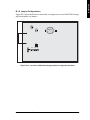
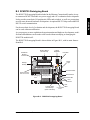
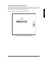
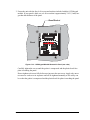
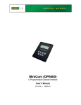
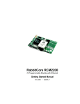
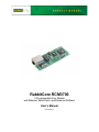
The RCM3700 Prototyping Board included in the RCM3700 Development Kit makes it easy to connect an RCM3700 module to a power supply and a PC workstation for development. It also provides some basic I/O peripherals (RS-232, RS-485, A/D converter, IrDA transceiver, LEDs, and switches), as well as a prototyping area for more advanced hardware development. For the most basic level of evaluation and development, the RCM3700 Prototyping Board can be used without modification. As you progress to more sophisticated experimentation and hardware development, modifications and additions can be made to the board without modifying or damaging the RCM3700 module itself. The RCM3700 Prototyping Board is shown below in Figure B-1, with its main features identified. RS-232 Header RXC TXC RXE R8 R7 NC D4 D2 D0 A1 A3 GND LED6 LED4 LED2 LED0 /RSTET +V D6 +3.3V D7 D5 D3 D1 A0 A2 GND GND LED5 /CS LED1 LED3 D2 D4 D6 GND D5 D7 GND LCD1JC D3 LCD1JB D0 CX5 JP7 /CS NC NC NC NC NC NC R26 JP6 D1 CX3 CX4 UX1 JP5 A1 VBAT CX2 A1 PD4 SMT Prototyping Area R24 C28 +BKLT PE1 A3 CX1 RP1 JP4 U8 Through-Hole Prototyping Area PE5 A2 PG7_RXE PC0_TXD GND PE0 PG6 TXE PD5 LED6 PC1/PG2 LED4 PF6 LED2 PF5 PF7 PC3/ PG3 PC2 TXC PE4 +5 V, 3.3 V, and GND Buses LCD1JA GND PF4 BT1 LDE0 PF1 R15 GND +5V /RESET /RES LED5 PB0 +V PA6 PA7 PF0 LED3 1 2 R22 R23 C24 C25 C27 R25 PA6 PA4 PA2 PA0 PF0 PB2 PB4 PB7 PC1/ PF7 PG2 PF5 PC3/PG3 C21 L2 R18 R19 R20 C23 U7 PA5 PB7 R14 LED1 C26 R21 PE5 PD4 GND /RES /IOWR PG7 RXE C20 PE1 C22 GND TXE PA7 PA5 PA3 PA1 PF1 PB0 PB3 PB5 PF4 PF6 PE7 PE4 PE0 PC0_TXD PC2_TXC PG6_TXE /IORD PD5 VBAT TCM_SMT_SOCKET GND +5V R13 J5 PA3 PA1 C11 C53 DCIN U2 C18 U6 C17 U5 +BKLT C7 PA0 +5V R12 PB3 PB2 GND R11 PB5 PB4 L1 C16 /IORD PE7 +3.3V C9 U3 U4 PA4 PA2 GND C6 D2 C13 GND GND /IOWR GND JP2 C4 C3 TXD 485 +485 C5 RXD J1 R5 R16 C19 D1 C12 C8 C10 Tx Rx JP1 R1 R2 R3 R4 C14 C15 J4 R9 IR1 R6 U1 J2 C2 RCM3700 Module Connector GND C1 Power Input +5V IRDA Transceiver Backup Battery RCM3700 Module Extension Header GND RS-485 CX6 R27 CX7 R28 CX8 C35 R43 UX2 01 R41 R42 03 04 00 C34 AIN C32 02 C33 C30 C31 R39 R40 R35 R36 CX11 AGND AGND VREF C29 R44 THERM_IN R37 THERMISTOR CONVERT R31 R32 R33 R34 AIN R38 06 JP8 J7 05 R30 R29 DS1 CX9 CX10 DS3 DS2 J8 R48 RCM36/37XX SERIES PROTOTYPING BOARD RCM3700 B.1 RCM3700 Prototyping Board R45 R49 R46 R47 RESET S1 Analog Reference Convert Ground S2 S3 Power LED Analog Inputs User LEDs User Switches Reset Switch LCD/Keypad Module Connections Figure B-1. RCM3700 Prototyping Board RabbitCore RCM3700 User’s Manual 91