1
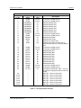
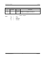
Evaluation Kit for CMX990
EV9900A
Differential Amplifiers
Simple circuits are provided to allow evaluation of the differential amps on the CMX990 (R117,
R118, R119, R120, R121, R122, R123, R124, C156 and C157).
Temperature Sensors
Two temperature sensors are provided, one (U21) adjacent to the PAs and the other (U19)
adjacent to the VCTCXO. These are connected to the CMX990 Aux ADC inputs 0 and 1
respectively.
Tx/Rx Switch
Although not configured in the default EV9900A build, circuits are provided to implement a Tx / Rx
switch using PIN diodes. (See section 6.2.1)
Interface
The EV9900A provides access to the CMX990 parallel interface via connector J13.
The EV9900A has test pins to allow measurement of aux DAC outputs and test pins that allow the
user to apply test signals to the aux ADC inputs.
All RF connectors are SMA type.
The power connector provides two separate power connections: one for the power amplifier and
the other to supply all other circuits.
6.2
Adjustments and Controls
The user has the ability to configure the EV9900A for a number of different operational scenarios.
6.2.1
Tx/Rx Switch
The following modifications need to be implemented on the EV9900A (PCB546F) evaluation
board to enable a classical series-shunt RX/TX switch.
Ref
Des
R194
C172
C94
L21
C212
L16
C213
C226
410-430MHz
value
100R
1n0
1n0
100nH 1008CS
1n0
15nH 0603CS
6p8
6p8
The receiver path components (L16, C213, C226) form a lumped quarter wave section and will
need to vary dependent upon the users’ operating band. L21 would also require a value change.
The switch will give less than 1dB insertion loss.
The main consequence with this topology is that only one control line is required and the logic is
as follows; TX_ON = 3V (HIGH) => TX mode, TX_ON = 0V (LOW) => RX mode. This signal is
buffered by TR13 and TR14 due to the current required for low transmit through loss.
© 2007 CML Microsystems Plc
18
UM9900A/3