1
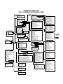
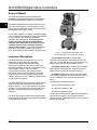
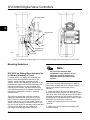
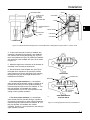
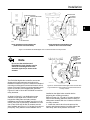
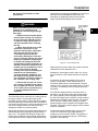
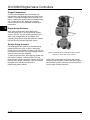
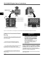
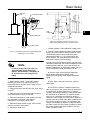
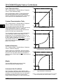
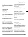
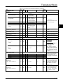
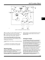
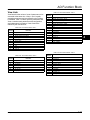
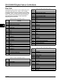
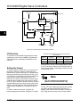
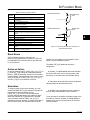
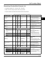
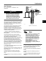
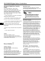
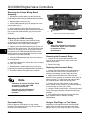
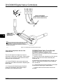
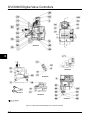
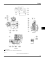
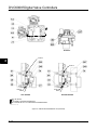
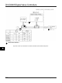
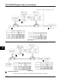
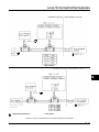
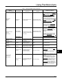
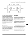
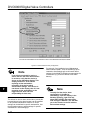
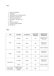
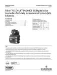
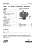
Installation
STARTING POSITION OF TRAVEL
INDICATOR ASSEMBLY (DIGITAL
VALVE CONTROLLER OUTPUT A
AT 0 PSI. )
IN THIS POSITION, THE “B” HOLE
IN THE FEEDBACK ARM WILL BE
ALIGNED WITH THE REFERENCE
HOLE IN THE DIGITAL VALVE
CONTROLLERS HOUSING.
E0989 / DOC
DVC6030f FEEDBACK
ARM MOVEMENT
2
MOVEMENT OF TRAVEL
INDICATOR ASSEMBLY WITH
INCREASING PRESSURE FROM
OUTPUT A.
ACTUATOR SHAFT MOVEMENT
STARTING POSITION OF THE ACTUATOR TRAVEL
INDICATOR ASSEMBLY IF INCREASING PRESSURE
FROM OUTPUT A DRIVES THE INDICATOR
COUNTERCLOCKWISE (THE POTENTIOMETER
SHAFT WILL ROTATE CLOCKWISE AS VIEWED
FROM THE BACK OF THE FIELDVUE INSTRUMENT)
DVC6030f FEEDBACK
ARM MOVEMENT
19B3879-A
NOTE: DVC6030f TRAVEL COUNTS (CLOCKWISE) = 13400 $ 700
Figure 2-9. Explanation of FIELDVUE DVC6030f Travel Indicator Starting Position and Movement, if Clockwise Orientation
is Selected for “Travel Sensor Motion” in ValveLink Software or the Field Communicator
actuator, makes pneumatic connections to the
actuator, sets up, and calibrates the instrument. If you
purchased the digital valve controller separately, you
will need a mounting kit to mount the digital valve
controller on the actuator. See the instructions that
come with the mounting kit for detailed information on
mounting the digital valve controller to a specific
actuator model.
measures stay in effect while working on the
equipment.
Figure 2-7 shows the DVC6030f digital valve controller
mounted on a quarter-turn actuator. Refer to figure 2-7
for parts locations. Refer to the following guidelines
when mounting on quarter-turn actuators:
4. If required, attach the spacer to the actuator shaft.
Note
Due to NAMUR mounting limitations,
do not use the stainless steel
DVC6030f in high vibration service.
1. Isolate the control valve from the process line
pressure and release pressure from both sides of the
valve body. Shut off all pressure lines to the pneumatic
actuator, releasing all pressure from the actuator. Use
lock-out procedures to be sure that the above
September 2013
2. If necessary, remove the existing hub from the
actuator shaft.
3. If a positioner plate is required, attach the
positioner plate to the actuator as described in the
mounting kit instructions.
Refer to figures 2-9 and 2-10. The travel indicator
assembly can have a starting position of 7:30 or
10:30. Determine the desired starting position then
proceed with the next step. Considering the top of the
digital valve controller as the 12 o’clock position, in the
next step attach the travel indicator, so that the pin is
positioned as follows:
If increasing pressure from the digital valve
controller output A rotates the potentiometer shaft
clockwise (as viewed from the back of the
instrument), mount the travel indicator assembly such
that the arrow is in the 10:30 position, as shown in
figure 2-9.
If increasing pressure from the digital valve
controller output A rotates the potentiometer shaft
counterclockwise (as viewed from the back of the
instrument), mount the travel indicator assembly such
that the arrow is in the 7:30 position, as shown in
figure 2-10.
2-11