1
USER MANUAL
RadioNet
Document Update
Revision
Draft
Description of Change
Original Version
Application
Version
PoleNet
RadioNet Host
RadioNet Base
RadioNet Remote
NMC Pro
V1.61 or greater
V1.61 or greater
V2.27 or greater
V2.27 or greater
V3.02.08 or greater
Date of issue:
Publisher:
2nd July 2009
Netafim TM (A.C.S.) Ltd.
Change
Number
0000
Date
20090702
Approval
P.Bail
© Copyright 2009, Netafim
No part of this publication may be reproduced, stored in an automated data file or made public in any form or by any
means, whether electronic, mechanical, by photocopying, recording or in any other manner without prior written
permission of the publisher.
Although Netafim takes the greatest possible care both with its products and the associated manuals, there may be
discrepancies in them.
Netafim will not however accept responsibility for damage resulting from the use of Netafim products or damage
resulting from the use of this manual. Netafim also reserves the right to make changes and improvements to its
products or to the associated manuals without notice.
Doc. Name: RadioNet - User Manual
Revision: 01
Crop Management Technologies
Page: - 2 - of 98 pages
USER MANUAL
RadioNet
Table of Context
1. Introduction................................................................................................................................. - 6 - 2. PC Software - PoleNet................................................................................................................ - 7 - 3. Quick Start Guide ....................................................................................................................... - 8 - 3.1. 3.2. 3.3. 3.4. 3.5. 4. PC Communication Connections ........................................................................................... - 10 - 4.1. 4.2. 4.3. 4.4. 4.5. 4.6. 5. Quick Start Guide – Remote Unit Pre Installation.........................................................................................- 8 - Quick Start Guide – Base Unit ......................................................................................................................- 8 - Quick Start Guide – Host Unit .......................................................................................................................- 8 - Quick Start Guide – Remote Unit Post Installation .......................................................................................- 9 - Quick Start Guide – Host Unit Post Installation ............................................................................................- 9 - PC Specifications ........................................................................................................................................- 10 - PC Communication Connection to RadioNet Host Unit ..............................................................................- 11 - PC Communication Connection to RadioNet Base Unit .............................................................................- 12 - PC Communication Connection to RadioNet Remote Unit.........................................................................- 13 - PC Communication Connection to RadioNet Survey Unit ..........................................................................- 14 - PoleNet Advanced Mode ............................................................................................................................- 15 - Configuration Guide Lines ...................................................................................................... - 16 - 5.1. Configuration – Remote Unit Pre Installation..............................................................................................- 16 - 5.1.1. Setup Agile Remote Radio Settings Definitions..................................................................................- 17 - 5.2. Configuration – Base Unit ...........................................................................................................................- 20 - 5.2.1. Setup Agile Base Radio Settings ........................................................................................................- 20 - 5.2.2. Setup Agile Base Radio Settings Definitions ......................................................................................- 21 - 5.2.3. Base Unit - Route Map........................................................................................................................- 23 - 5.3. Configuration – Host Unit ............................................................................................................................- 26 - 5.3.1.1. Definitions of Host Unit – System Settings......................................................................................- 26 - 5.3.1.2. Definitions of Host Monitor Mode – Networks Tab..........................................................................- 28 - 5.4. Configuration – RadioNet Remotes Unit Post Installation ..........................................................................- 30 - 5.4.1.1. Definition of Radio Remote Monitor – Ins & Outs Tab ....................................................................- 32 - 5.5. Configuration – RadioNet Host Unit Post Installation .................................................................................- 33 - 5.5.1.1. Definitions of Host Monitor Mode – Units Tab ................................................................................- 34 - 5.5.1.2. Definitions of Host Monitor Mode – Dig Ins Tab .............................................................................- 36 - 5.5.1.3. Definitions of Host Monitor Mode – Dig Outs Tab...........................................................................- 37 - Doc. Name: RadioNet - User Manual
Revision: 01
Crop Management Technologies
Page: - 3 - of 98 pages
USER MANUAL
RadioNet
6. Configurations – Host Controllers.......................................................................................... - 39 - 6.1. Configuration - For NMC-Pro ......................................................................................................................- 39 - 6.1.1. Setup Agile Host Unit – Configure Controller Definitions....................................................................- 41 - 6.1.2. Mapping of NMC Address Settings Definitions ...................................................................................- 43 - 6.2. Explanation – Host Unit Expansion Cards ..................................................................................................- 46 - 6.3. Configuration – Host Unit Expansion Card, 48 Parallel Inputs ...................................................................- 47 - 6.3.1. Mapping of Parallel Controller Input Address Settings Definitions .....................................................- 49 - 6.4. Configuration – Host Unit Expansion Card, 48 Output (Input Playback) ....................................................- 52 - 6.4.1. Mapping of Parallel Controller Output Address Settings Definitions...................................................- 54 - 7. Diagnostics & Trouble Shooting Guide ................................................................................. - 57 - 7.4. Diagnostics – Host ......................................................................................................................................- 58 - 7.4.1. Host Diagnostics – Hardware..............................................................................................................- 58 - 7.4.2. Host Unit Diagnostics – Software........................................................................................................- 60 - 7.4.2.1. Host Unit Diagnostics - Networks....................................................................................................- 60 - 7.4.2.2. Definitions of Host Monitor Mode – Networks Tab..........................................................................- 61 - 7.4.2.3. Host Unit Diagnostics - Base & Remote Units ................................................................................- 62 - 7.4.2.4. Definitions of Host Monitor Mode – Units Tab ................................................................................- 62 - 7.4.2.5. Host Unit Diagnostics - Digital Inputs..............................................................................................- 65 - 7.4.2.6. Definitions of Host Monitor Mode – Dig Ins Tab .............................................................................- 65 - 7.4.2.7. Host Diagnostics - Digital Outputs ..................................................................................................- 66 - 7.4.2.8. Definitions of Host Monitor Mode – Dig Outs Tab...........................................................................- 66 - 7.4.2.9. Host Unit Diagnostics - Routing ......................................................................................................- 68 - 7.4.2.10. Host Unit Diagnostics - System.......................................................................................................- 69 - 7.5. Diagnostics – Base Unit ..............................................................................................................................- 70 - 7.5.1. Base Unit Diagnostics – Hardware .....................................................................................................- 70 - 7.5.2. Base Unit Diagnostics – Software.......................................................................................................- 71 - 7.5.2.1. Definitions of Radio Base Monitor – Route Tab..............................................................................- 72 - 7.5.2.2. Definition of Radio Remote Monitor – Allowed Units Tab ...............................................................- 73 - 7.5.2.3. Definition of Radio Remote Monitor – Cards Tab ...........................................................................- 74 - 7.6. Diagnostics – Remote Unit..........................................................................................................................- 75 - 7.6.1. Remote Unit Diagnostics – Hardware .................................................................................................- 75 - 7.6.2. Remote Unit Diagnostics – Software ..................................................................................................- 76 - 7.6.2.1. Definition of Radio Remote Monitor – Ins & Outs Tab ....................................................................- 77 - 7.6.2.2. Definition of Radio Remote Monitor – Cards Tab ...........................................................................- 78 - 8. Surveyor Mode.......................................................................................................................... - 79 - 8.4. Surveyor Mode - RSSI Floor .......................................................................................................................- 79 - 8.4.1. Definition of Radio Surveyor Mode – RSSI Floor Tab ........................................................................- 80 - 8.5. Surveyor Mode – Interference.....................................................................................................................- 81 - 8.5.1.1. Definition of Radio Surveyor Mode – Interference Tab...................................................................- 82 - 8.6. Surveyor Mode - Channel Quality ...............................................................................................................- 84 - 8.6.1. Signal Strength....................................................................................................................................- 84 - 8.6.2. Bit Error Rate (BER)............................................................................................................................- 85 - 8.6.2.1. Definition of Surveyor Mode – Channel Quality Tab.......................................................................- 86 - Doc. Name: RadioNet - User Manual
Revision: 01
Crop Management Technologies
Page: - 4 - of 98 pages
USER MANUAL
RadioNet
9. Firmware.................................................................................................................................... - 87 - 9.4. 9.5. 9.6. Firmware Upgrade Procedure for Remote Unit ..........................................................................................- 87 - Firmware Upgrade Procedure for Base Unit...............................................................................................- 88 - Firmware Upgrade Procedure for Host Unit................................................................................................- 89 - 10. Annex A ..................................................................................................................................... - 90 - 10.4. 10.5. Compatible Solenoid & Relay List...........................................................................................................- 90 - Izumi Relay Wiring Schematic ................................................................................................................- 91 - 11. Annex B ..................................................................................................................................... - 92 - Figure 11.1 Card position number..................................................................................................................- 92 - Figure 11.2 DI position number. .....................................................................................................................- 93 - Figure 11.3 DO position number. ...................................................................................................................- 94 - 12. Annex C ..................................................................................................................................... - 95 - 13. Annex D ..................................................................................................................................... - 96 - 14. Glossary .................................................................................................................................... - 98 - Doc. Name: RadioNet - User Manual
Revision: 01
Crop Management Technologies
Page: - 5 - of 98 pages
USER MANUAL
RadioNet
1.
Introduction
RadioNet by Netafim is the new generation of wireless control and monitoring systems. Extra detail has been
given to the RadioNet range of products to make it versatile, reliable and user friendly.
The 3 basic components include the Host, Base and Remote units.
The Host includes multi interfaces giving it the ability to integrate to a wide range of controllers commercially
available for horticultural automation.
The RadioNet Base can manages up to 254 remote units in a wireless network including the option of using
multi layer store & forward (SAF) repeaters.
The RadioNet remote units are modular in size from 1,3,5,7 and 9 digital outputs.
Establishing wireless connectivity presents a unique set of challenges, which often includes natural obstacles,
remote locations and distant central office. There is a need for amplified reliability to protect against
unplanned downtime in the operation process. There may be already-in-use technologies that will not enable
wired solution (retrofit).
Understanding these issues and how to address them is essential in deploying a remote wireless solution.
Netafim's broad-base design, manufacturing and engineering capabilities gives RadioNet the distinct
advantage of having a full control and monitoring solution under one reliable system.
Its superior communication, connectivity and programmability makes RadioNet an agile system that enhances
the performance, data and operating reliability of remote sites.
Doc. Name: RadioNet - User Manual
Revision: 01
Crop Management Technologies
Page: - 6 - of 98 pages
USER MANUAL
RadioNet
2.
PC Software - PoleNet
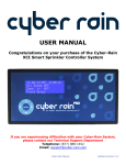
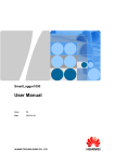
The PoleNet PC software includes three basic functions.
Configuration tools for the RadioNet & SingleNet Hardware.
Local & remote diagnostic tools for the RadioNet & SingleNet Hardware.
Conducting radio survey analysis for the RadioNet System.
Host
Base
RTU
Configuration tools include programming of the radio, mapping, network management and setting alarm levels.
Diagnostics tools include the testing of digital inputs and outputs, monitoring signal strengths, battery voltages and
operating temperatures.
As RF signals are invisible, the PoleNet PC software provides us with additional user friendly tools to assist in
designing and managing and diagnosing RF networks.
Base
Remote
Doc. Name: RadioNet - User Manual
Revision: 01
Crop Management Technologies
Page: - 7 - of 98 pages
USER MANUAL
RadioNet
3.
Quick Start Guide
The Quick start guide is intended for advanced operators who only require a logical sequence to follow.
3.1. Quick Start Guide – Remote Unit Pre Installation
Check Wiring
Power Up Remote Unit and view diagnostic LED
Note:
LED function is disabled when RS232 communication port is active.
Configure Remote Unit: frequency, transmit power, battery voltage alarm levels and I/O configurations
3.2. Quick Start Guide – Base Unit
Check Wiring
Power Up Base Unit and view diagnostic LED’s
Note:
LED function is disabled when RS232 communication port is active.
Configure Base Unit: frequency, transmit power and battery voltage alarm levels
Draw site map with ESN locations and I/O capacity
Define SAF Unit ID and locations
Create Route Map text file
Load Route Map & confirm
3.3. Quick Start Guide – Host Unit
Reset Host Unit
View available Networks to confirm
View Routing and Unit ID’s to confirm network structure as per Route Map
Doc. Name: RadioNet - User Manual
Revision: 01
Crop Management Technologies
Page: - 8 - of 98 pages
USER MANUAL
RadioNet
3.4. Quick Start Guide – Remote Unit Post Installation
Check Wiring of Power, solar panel orientation (if applicable), Digital Inputs, Digital Outputs, and antenna
connection for firmness
Power Up Remote Unit and view diagnostic LED
Note:
LED function is disabled when RS232 communication port is active.
View battery voltage level and test digital inputs and digital outputs.
Note:
When unit is powered up, all the digital outputs will close in sequence, 1,2,3,etc.
3.5. Quick Start Guide – Host Unit Post Installation
Define System Parameters
Configure “Refresh remotes” time
Configure “Digital output delay” time
Clear Capture & Reset Host unit
Note:
Clear Capture resets Captured information and controller I/O mapping configurations.
Capture Data
Select Control Mode
Configure Controller
Complete RadioNet Host to Controller Mapping form
Define communication settings
Define digital output mapping
Define digital input mapping
Save backup data and program Host Unit
Test I/O via Host (excludes controller I/O function)
Note:
Make sure communication cable between Host and controller is disconnected.
Test via Controller
Note:
Make sure communication cable between Host and controller is connected.
Doc. Name: RadioNet - User Manual
Revision: 01
Crop Management Technologies
Page: - 9 - of 98 pages
USER MANUAL
RadioNet
4.
PC Communication Connections
4.1. PC Specifications
Description
Operating System:
Windows 98, ME, 2000, NT, XP, Vista
Processor:
Pentium IV 1.6 GHZ – Minimum
Memory:
500 MB RAM – Minimum
Graphics Display:
XGA resolution capable (1024 x 768, 65000 colours)
Serial Port:
1 free serial port preferred
1 free USB port with USB to serial converter (optional)
Hard Drive:
2 GB available free space - Minimum
Doc. Name: RadioNet - User Manual
Revision: 01
Crop Management Technologies
Page: - 10 - of 98 pages
USER MANUAL
RadioNet
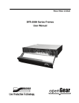
4.2. PC Communication Connection to RadioNet Host Unit
Step 1 Connect communication lead
Option 1.A
Host Unit - Direct communication connection via Serial Port (DB9 Male)
Option 1.B
Host Unit - Direct communication connection via USB Port
Step 2 Start PoleNet PC Software
Note:
Disable any device or software program that may conflict with the use of your serial port
Step 3 Configure connection & connect
3.1
3.2
3.3
3.4
3.5
Select Configure Connection Button
Select device to connect to PC - Agile Host
Select serial port number
Select OK button
Select Connection Button
Doc. Name: RadioNet - User Manual
Revision: 01
Crop Management Technologies
Page: - 11 - of 98 pages
USER MANUAL
RadioNet
4.3. PC Communication Connection to RadioNet Base Unit
Step 1 Connect communication lead
Option 1.A
Base Unit - Direct communication connection via Serial Port (DB9 Male)
Option 1.B
Base Unit - Direct communication connection via USB Port
Step 2 Start PoleNet PC Software
Note:
Disable any device or software program that may conflict with the use of your serial port
Step 3 Configure connection & connect
3.1
3.2
3.3
3.4
3.5
Select Configure Connection Button
Select device to connect to PC - Agile Radio V2
Select serial port number
Select OK button
Select Connection Button
Doc. Name: RadioNet - User Manual
Revision: 01
Crop Management Technologies
Page: - 12 - of 98 pages
USER MANUAL
RadioNet
4.4. PC Communication Connection to RadioNet Remote Unit
Step 1 Connect communication lead
Option 1.A
Remote Unit - Direct communication connection via Serial Port (DB9 Male)
Option 1.B
Remote Unit - Direct communication connection via USB Port
Step 2 Start PoleNet PC Software
Note:
Disable any device or software program that may conflict with the use of your serial port
Step 3 Configure connection & connect
3.1
3.2
3.3
3.4
3.5
Select Configure Connection Button
Select device to connect to PC - Agile Radio V2
Select serial port number
Select OK button
Select Connection Button
Doc. Name: RadioNet - User Manual
Revision: 01
Crop Management Technologies
Page: - 13 - of 98 pages
USER MANUAL
RadioNet
4.5. PC Communication Connection to RadioNet Survey Unit
Step 1 Connect communication lead
Option 1.A
Remote Unit - Direct communication connection via Serial Port (DB9 Male)
Option 1.B
Remote Unit - Direct communication connection via USB Port
Step 2 Start PoleNet PC Software
Note:
Disable any device or software program that may conflict with the use of your serial port
Step 3 Configure connection & connect
3.1
3.2
3.3
3.4
3.5
Select Configure Connection Button
Select device to connect to PC - Agile Surveyor
Select serial port number
Select OK button
Select Connection Button
Doc. Name: RadioNet - User Manual
Revision: 01
Crop Management Technologies
Page: - 14 - of 98 pages
USER MANUAL
RadioNet
4.6. PoleNet Advanced Mode
Important functions and commands that can cripple the RadioNet system are hidden from day to day
operations.
The advance mode is used to activate important dialog boxes and command buttons such as:
System Capture
Clear Capture
Testing of outputs
Only accredited RadioNet Technicians should use the advanced features and once the commissioning and
testing phase has been completed, the advanced features should be deactivated.
Step 1 Start PoleNet Software
1.1
1.2
1.3
Select “Configure Connection” Button
Select “Advanced” Button
Select OK button
Note:
When advance mode is active, you will see Modem Configuration dialog box appear
Doc. Name: RadioNet - User Manual
Revision: 01
Crop Management Technologies
Page: - 15 - of 98 pages
USER MANUAL
RadioNet
5.
Configuration Guide Lines
5.1. Configuration – Remote Unit Pre Installation
Step 1 Confirm Radio Frequency for this project.
Step 2 Compile Site Map
Step 3 Setup programming bench
Step 4 Connect communication cable between PC and Remote unit, start PoleNet PC software, configure connection
and connect. (refer chapter 4.4)
Step 5 Access Agile Radio – Remote Settings
5.1
Select Setup Agile Radio Button
5.2
Select OK button to confirm Warning
Doc. Name: RadioNet - User Manual
Revision: 01
Crop Management Technologies
Page: - 16 - of 98 pages
USER MANUAL
RadioNet
Step 6 Setup Agile Radio – Remote Unit
Note:
All numeric settings must be performed by using the Up or Down arrows.
6.1
6.2
6.3
6.4
6.5
6.6
6.7
6.8
6.9
Select Channel Spacing & Offset (if applicable)
Define Operating Frequency
Define Output Power
Define Battery Thresholds
Define Output Firing Voltage
Enable/Disable Open Circuit Detection
Define Comm. check interval when outputs are Idle
Define Comm. check interval when outputs are Active
Select Reprogram Button or Cancel
5.1.1. Setup Agile Remote Radio Settings Definitions
Channel Spacing & Offset:
The channel spacing is configurable to either 12.5 kHz or 25 kHz. The channel spacing setting (default 12.5 KHz)
determines the next frequency increment.
For those countries that support channel spacing of 6.25 kHz, then selecting the 6.25 kHz offset will enable the center
frequency to offset by 6.25 kHz.
Operating Frequency:
The Agile Radio’s operating frequency is software configurable between 402 MHz and 470 MHz. The programmed
frequency must comply with either your local or national RF spectrum licensing organisation.
Note:
All RadioNet Remotes and the RadioNet Base must all be set to the same frequency.
Doc. Name: RadioNet - User Manual
Revision: 01
Crop Management Technologies
Page: - 17 - of 98 pages
USER MANUAL
RadioNet
Output Power:
The Agile Radio’s operating power is software configurable between 1mW and 500 mW. The Output power setting
should be equal or less than that defined by the radio license parameters that you are operating under.
Note: If the power setting is above 10mW, do not power up the RadioNet without an antenna connected.
Battery Thresholds:
Four Battery alarm thresholds can be set to advise the RadioNet Host when different battery voltage levels are
sensed. While on the network, crossing any of these thresholds causes the Host unit to be notified.
Good: Battery voltage is OK.
Warn: Battery voltage has reached the “warning level”, should a rechargeable power supply be installed, further
investigation would be required to determine why the battery voltage can’t be maintained at a good level.
IE: The solar panel might need cleaning or rechecking for correct orientation.
Low:
Battery voltage has reached the “low” level, should a rechargeable power supply be installed, further
investigation would be required to determine why the battery voltage can’t be maintained at a good level.
IE: The solar panel might need cleaning or rechecking for correct orientation.
Failed: Battery voltage has dropped below the “Failed” threshold. The RadioNet Remote sends an alarm message
and then turns off all outputs, stops monitoring the inputs, turns off the radio and goes into hibernation,
periodically awakening to check if the battery voltage has recovered.
Note:
Please refer to the Diagnostic section to view the current battery voltage level.
Doc. Name: RadioNet - User Manual
Revision: 01
Crop Management Technologies
Page: - 18 - of 98 pages
USER MANUAL
RadioNet
Output Firing Voltage:
The Output firing voltage (default 12 VDC) is user configurable between 9 – 16 VDC. This setting is a global setting
and effects all the outputs within the RadioNet Remote unit to which you are connected. When non standard solenoids
and relays are being used, please contact Netafim Technical Support for further assistance.
Note:
Note:
Please refer to the Diagnostic section for testing of the digital outputs.
Refer to annex A for Solenoid & Relay compatibility list.
Open Circuit Detection:
Each output of the RadioNet Remote has Open Circuit (O/C) detection enabled as default. When ever the output is
activated the RadioNet checks to see if a solenoid or relay has been connected. If no device has been detected, the
RadioNet will send an alarm message to the RadioNet Host and will also display the status in PoleNet monitor mode.
Should a non standard solenoid or relay be used and the open circuit alarm condition is unwarranted, then the user
can disable that particular individual output.
Note:
Note:
Please refer to the Diagnostic section for testing of the digital outputs.
Refer the annex B for correlation between the output address and physical output location.
Comm. Check:
A communication check between the RadioNet Remote and its Master can be user defined. There are two
independent intervals which are user configurable.
Note:
The Master can be either the base Unit or a SAF Remote Unit.
When idle:
Configurable between “Off” and 36 hours
Output On:
Configurable between “Off” and 2 hours 15 minutes.
Should an output be active and the Remote unit loses communication with its master within the
defined time limit, The Remote unit will close down all active outputs until re-connection is
established.
Doc. Name: RadioNet - User Manual
Revision: 01
Crop Management Technologies
Page: - 19 - of 98 pages
USER MANUAL
RadioNet
5.2. Configuration – Base Unit
5.2.1.
Setup Agile Base Radio Settings
Step 1 Connect communication cable between PC and Base unit, start PoleNet PC software, configure connection
and connect. (refer chapter 4.3)
Step 2 Access Agile Radio – Base Settings
2.1
Select Setup Agile Radio Button
2.2
Select OK button to confirm Warning
Step 3 Setup Agile Radio – Base unit
Note:
All numeric settings must be performed by using the Up or Down arrows.
3.1
3.2
3.3
3.4
3.5
Select Channel Spacing & Offset (if applicable)
Define Operating Frequency
Define Output Power
Define Battery Thresholds
Select Re Program Button or Cancel
Doc. Name: RadioNet - User Manual
Revision: 01
Crop Management Technologies
Page: - 20 - of 98 pages
USER MANUAL
RadioNet
5.2.2. Setup Agile Base Radio Settings Definitions
Channel Spacing & Offset:
The channel spacing is configurable to either 12.5 kHz or 25 kHz. The channel spacing setting (default 12.5 KHz)
determines the next frequency increment.
For those countries that support channel spacing of 6.25 kHz, then selecting the 6.25 kHz offset will enable the center
frequency to offset by 6.25 kHz.
Operating Frequency:
The Agile Radio’s operating frequency is software configurable between 402 MHz and 470 MHz. The programmed
frequency must comply with either your local or national RF spectrum licensing organisation.
Note:
All RadioNet Remotes and the RadioNet Base must all be set to the same frequency.
Output Power:
The Agile Radio’s operating power is software configurable between 1mW and 500 mW. The Output power setting
should be equal or less than that defined by the radio license parameters that you are operating under.
Note: If the power setting is above 10mW, do not power up the RadioNet without an antenna connected.
Doc. Name: RadioNet - User Manual
Revision: 01
Crop Management Technologies
Page: - 21 - of 98 pages
USER MANUAL
RadioNet
Battery Thresholds:
Four Battery alarm thresholds can be set to advise the RadioNet Host when different battery voltage levels are
sensed. While on the network, crossing any of these thresholds causes the Host unit to be notified.
Good: Battery voltage is OK.
Warn: Battery voltage has reached the “warning level”, should a rechargeable power supply be installed, further
investigation would be required to determine why the battery voltage can’t be maintained at a good level.
IE: The solar panel might need cleaning or rechecking for correct orientation.
Low:
Battery voltage has reached the “low” level, should a rechargeable power supply be installed, further
investigation would be required to determine why the battery voltage can’t be maintained at a good level.
IE: The solar panel might need cleaning or rechecking for correct orientation.
Failed: Battery voltage has dropped below the “Failed” threshold. The RadioNet Remote sends an alarm message
and then turns off all outputs, stops monitoring the inputs, turns off the radio and goes into hibernation,
periodically awakening to check if the battery voltage has recovered.
Note:
Please refer to the Diagnostic section to view the current battery voltage level.
Doc. Name: RadioNet - User Manual
Revision: 01
Crop Management Technologies
Page: - 22 - of 98 pages
USER MANUAL
RadioNet
5.2.3. Base Unit - Route Map
A Route Map is a data file that explains who is part of this wireless network and automatically configures their
function. Since the network consists of one or more remote units, each unit must be given a unique ID. The
ID of each unit is derived from a unique electronic serial number called an ESN. The ESN number becomes
part of the unit’s identification (ID).
A Route Map is generated from a text file and programmed into the RadioNet Base unit via the PoleNet PC
Software. Once the Route Map has been programmed, the RadioNet Base unit transmits a message to all
units to perform a reset. Once the network has been reset, the Remotes units will start to report into the
RadioNet Base unit to see if they have any additional functions to perform, such as to act as a Store and
Forward Remote unit (SAF).
The wireless network synchronizes to a preset cycle time. The cycle time is determined by the number of
remote units and the number of layers within the network. The cycle time may vary between 4, 8, 16 and 32
seconds.
Step 1 Draw a site map and mark the location of the Remote unit ID. This site map should include those units that
have been defined to act as SAF Remote units
Doc. Name: RadioNet - User Manual
Revision: 01
Crop Management Technologies
Page: - 23 - of 98 pages
USER MANUAL
RadioNet
Step 2 Open up a blank text file.
(right mouse click on your desktop, select New, Text Document).
An icon will appear on the desktop which requires you to give the document a new name.
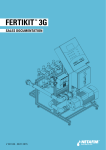
Step 3 Open the blank text document and enter the units ESN numbers.
The network layout is determined by the location and order of certain symbols.
The semicolon ; is inserted at the end of a Remote units ID (individually listed units).
EG:
20200101;
20200102;
Where you have consecutive ESN’s, you may add .. between the Remote units ID (signifying a range).
EG:
20200103..20200105;
To designate a Store and Forward Remote unit (SAF), it must not be part of a range, and should be followed
by an opening brace, the list of Remote units it is responsible for, and a closing brace. EG:
20200102{20200111..20200114}
Store and Forward Remote units (SAF) can be nested allowing multiple SAF Remote units in series (layers).
EG:
20200106{20200121;20200123;
20200120{20200115..20200119;
20200122{20200124..20200128}}}
3.1
Save file.
Doc. Name: RadioNet - User Manual
Revision: 01
Crop Management Technologies
Page: - 24 - of 98 pages
USER MANUAL
RadioNet
Step 4 Connect communication cable between the PC and Base Unit, start PoleNet PC software, configure
connection and connect. (refer chapter 4.3)
Note:
Advanced mode must be selected. (refer chapter 4.6)
Step 5 Access Agile Base Radio – Load Route Table
5.1
5.2
5.3
5.4
5.5
5.6
5.7
5.8
Select “Load Route Table” Button
Select Load Button
Select file location of stored Route Map
Select route map text file
Select Open button
Select Load button
Confirm the file has loaded correctly without any errors.
Correct errors if any, then reload.
Select the Program button to download route map file into RadioNet Base
Confirm that the route data has been programmed successfully
Note: It maybe necessary to repeats steps 2 to 8 until you confirm route data has been programmed successfully.
5.9
Select Close Button when completed.
Doc. Name: RadioNet - User Manual
Revision: 01
Crop Management Technologies
Page: - 25 - of 98 pages
USER MANUAL
RadioNet
5.3. Configuration – Host Unit
Step 1 Connect communication cable between PC and Host unit, start PoleNet PC software, configure connection
and connect. (refer chapter 4.2)
Step 2 Access Agile Host – System
2.1
Select System button
Step 3
3.1
3.2
3.2
Configure Host Unit system settings
Define Refresh Remotes interval
Define Digital Output delayed activation time
Select the OK button to confirm changes
5.3.1.1.
Definitions of Host Unit – System Settings
Refresh Remotes:
The refresh remotes time is the interval in which the Host Unit will force a communication (poll)
with each of the Remote Units. This setting ranges from “Off” to a maximum time of “4 hours 15
minutes”. The default interval is set to “Off”.
Note:
Dout delay:
A more frequent setting will cause an increase in battery consumption in the Remotes Units.
As the communication with the Remotes Units are synchronized within each communication
cycle time (4,8,16 or 32 seconds), digital output activations are typically random over the
communication cycle time. By defining a digital output delay time, all the Remote Unit’s will
delay the activation until the master synchronization delay time.
EG: All the Remote Units know the master time. If the Dout delay was set to 30 seconds, the
controller sends it’s command to the Host Unit, which in turn, sends a signal to several Remote
Units to turn on. Each Remote Unit would delay there activation until the master time was
reached, therefore all the valves would typical turn on at the same period of time, approximately
30 seconds after the master controller initiated the command.
This setting ranges from “Off” to a maximum time of “15 minutes and 45 seconds”. The default
delay time is set to “Off”.
Doc. Name: RadioNet - User Manual
Revision: 01
Crop Management Technologies
Page: - 26 - of 98 pages
USER MANUAL
RadioNet
Step 2 Access Agile Host – Monitor
2.1
Select Monitor button
Step 3 Select “Networks” Tab
The monitor window provides an overview of the complete RadioNet system as viewed from the RadioNet
Host unit and Base unit.
Prior to configuring the RadioNet Host unit, we need to make sure that the route map data that has been
entered into the Base unit is also viewed correctly via the RadioNet Host Unit.
The screen is divided into 2 main sections.
The top portion of the display is Global System Information as viewed from the Host Unit and Base unit, while
the bottom portion displays information relating to tab selected, in this example the Tab Data displays the
available networks.
Global System
Information
Network Tab
Tab Data
Close Button
Doc. Name: RadioNet - User Manual
Revision: 01
Crop Management Technologies
Page: - 27 - of 98 pages
USER MANUAL
RadioNet
5.3.1.2.
Listed:
Definitions of Host Monitor Mode – Networks Tab
Displays the total number of devices (networks, units, I/O) that is theoretically available to both
the Host unit and the RadioNet Base unit.
Note:
Note:
The Base Radio unit is included as both a network and as a Remote unit.
The quantity of units is derived from the base unit plus the numbers of Remote units defined in the route
map.
Present:
Displays the total number of active devices (networks, units, I/O) that are currently connected to
the Host unit and the Base unit, either physically or via the wireless network.
Missing:
Displays the total number of devices (networks, units, I/O) that are captured, but the Host unit or
Base unit has not made a connection with.
Extra:
Displays the total number of devices (networks, units, I/O) as defined in the Host unit and Base
unit that has not been captured.
On:
Displays the total number of digital inputs and digital outputs that are currently “ON” within the
system
Network Tab:
Displays the status of the networks that are accessible
Units Tab:
Displays the status of the defined units, both Base unit and Remotes units that are accessible
Routing Tab:
Displays both the Network configuration and routing configuration as seen by both the Host unit
and Base unit.
Doc. Name: RadioNet - User Manual
Revision: 01
Crop Management Technologies
Page: - 28 - of 98 pages
USER MANUAL
RadioNet
Step 4 Select “Routing” Tab
The routing window provides an overview of the complete RadioNet system as viewed from the RadioNet
Host unit and Base unit
This information is derived from the route map that has been previously programmed into the RadioNet Base
unit.
The RadioNet Technician should confirm that the data displayed in the routing screen is identical to the site
map which has been compiled earlier.
Note:
Note:
Please confirm that the Host unit has been reset since the Route Map was downloaded into the Base unit.
Please allow up to 45 seconds after resetting Host unit.
Global System
Information
Routing Tab
Contract Data
SAF Unit
Tab Data
Expand Data
SAF Unit
Close Button
Doc. Name: RadioNet - User Manual
Revision: 01
Crop Management Technologies
Page: - 29 - of 98 pages
USER MANUAL
RadioNet
5.4. Configuration – RadioNet Remotes Unit Post Installation
Step 1
Confirm all wiring and connections such as power, solar panel orientation (if applicable), digital inputs,
digital outputs and antenna connections.
Note:
Refer to Installation Manual for correct wiring guide.
Step 2 Power up Remote unit and view diagnostic LED functions.
Step 3 Monitor sequence of solenoid’s turning off…
Note:
If solenoid or relay is already de-energized, you may not hear or see a change of state.
Step 3 Connect communication cable between PC and Remote unit, start PoleNet PC software, configure
connection, select Advanced Mode and connect. (refer chapter 4.4)
Step 4 Access Agile Radio – Monitor mode
4.1
Select “Monitor” Button
Doc. Name: RadioNet - User Manual
Revision: 01
Crop Management Technologies
Page: - 30 - of 98 pages
USER MANUAL
RadioNet
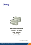
Step 5 Testing digital inputs and digital outputs
5.1
Select “Ins & Outs” Tab
The list displays the current number of inputs and outputs that correlates to the number and type of hardware
that is connected and functional.
5.2
Test digital inputs by causing a change of state and viewing the status change in the monitor screen.
Ins & Outs
Tabs
Column
Headings
I/O
Number
Digital Output
Status
Battery
Voltage
Temperature
Test
Button
Signal
Strength
Close
Button
5.3
Test digital outputs
5.4
Select the “Test” button to enable the testing mode for the digital outputs.
5.5
Write mouse click on the required digital output number to open a manual command dialog box. Select the
mode of operation either “On” to activate the digital output or “Off” to deactivate the digital output.
Note:
The RadioNet Technician should confirm both the operation and that the solenoid or relay is wired to the correct corresponding digital
output number.
5.6
Confirm that the battery voltage is within specified guidelines.
Doc. Name: RadioNet - User Manual
Revision: 01
Crop Management Technologies
Page: - 31 - of 98 pages
USER MANUAL
RadioNet
5.4.1.1.
Definition of Radio Remote Monitor – Ins & Outs Tab
IO:
Logical Input/Output number available
As the I/O expansion cards are plug & play, the I/O number will only appear when the I/O card
is inserted and recognized.
Addr:
Physical Address of the I/O available.
This address will be used for mapping of the RadioNet I/O to the host controllers I/O.
State:
Current status of the Input/Output.
Inputs:
0 = OFF (open circuit)
Outputs:
0 = OFF (closed/idle)
Count:
1 = ON (closed circuit)
1 = ON (open/active)
Total number of inputs (pulses) counted
Note: Input counted from trailing edge of pulse.
Information:
Status of the command or state.
Override:
Output manually activated.
Faulty O/C:
Output detected that there is no solenoid or relay connected.
Faulty S/C:
Output detected that there is a Short Circuit.
Battery:
Current battery voltage level sensed by the RadioNet Remote unit.
RSSI:
Return Signal Strength Indicator displayed in dBm.
This is the signal strength recorded coming from the Master of this Remote unit. IE: the
received signal strength.
Note:
If the remote has no master, then the RSSI value represents the noise floor.
Temperature:
The current temperature reported of the internal radio board.
Test Button:
Selecting the Test Button puts the Remote unit in testing mode.
Right mouse click on the DO number will activate a manual command list “On” or “Off”, giving
the operator the option to manually operate the digital output.
Note:
Note:
Manual operation temporary overrides the Host unit operation and may generate a host controller alarm.
Disconnecting the communication cable from the Remote unit will automatically restore any manually
overridden digital outputs.
Doc. Name: RadioNet - User Manual
Revision: 01
Crop Management Technologies
Page: - 32 - of 98 pages
USER MANUAL
RadioNet
5.5. Configuration – RadioNet Host Unit Post Installation
Step 1 Connect communication cable between PC and Host unit, start PoleNet PC software, configure connection
and connect. (refer chapter 4.2)
Step 2 Access Agile Host – Monitor
2.1
Select Monitor button
Step 3 Select “Units” Tab
The monitor window provides a status overview of the Base unit and Remote Units as viewed from the
RadioNet Host unit and Base unit. Status information includes network, mapping, routing, signal strength,
battery voltage, battery condition, unit temperature and firmware version.
Global System
Information
Units Tab
Tab Data
Close Button
Doc. Name: RadioNet - User Manual
Revision: 01
Crop Management Technologies
Page: - 33 - of 98 pages
USER MANUAL
RadioNet
5.5.1.1.
Definitions of Host Monitor Mode – Units Tab
Unit:
Displays the Electronic Serial Number (ESN) of all the units that have been configured in the
route map.
Net:
Displays which network the unit belongs too.
Present:
Displays the current status of the unit, whether the unit is on-line or off-line.
No
=
Unit is off-line
Yes
=
Unit is on-line & available
Extra:
Displays the current status of the unit, whether the unit is available, or has not yet been
captured.
No
=
Unit has been captured
Yes
=
Unit has not been captured
Routed:
Displays the current status of the unit, whether the unit is on-line or off-line.
Missing =
Unit is off-line
Yes
=
Unit is on-line & available
Orphan =
Unit that has been adopted in the allowed list of the base (old route map), but
not included in the new route map
Rogue =
Unit that has been adopted by the Host (old route map) and is not on the
allowed list of the base.
Note:
If you see Orphan’s or Rogue’s, a Host unit reset should be performed.
State:
Displays the status of the unit.
Absent
=
Unit is off-line
Get I/O Cal
=
Unit is on-line & uploading I/O information
Set Mode
=
Unit is on-line & comm. mode is being set
Normal
=
Unit is on-line
Progress:
Displays the unit’s progress as it is coming on-line.
0%
=
Unit is off-line
100%
=
Unit is on-line & available
SAF Route:
Displays the remotes unit’s communication path via a Store and Forward (SAF) Repeater which
is also known as it’s Master.
RSSI:
Displays the received signal strength from the view point of the remote unit.
IE: the received signal strength from the remote unit’s Master.
Vbatt:
Displays the current battery voltage in the remote unit.
EG: 6.543V
Doc. Name: RadioNet - User Manual
Revision: 01
Crop Management Technologies
Page: - 34 - of 98 pages
USER MANUAL
RadioNet
Batt:
Displays the remote unit’s battery condition.
Ok
=
Battery okay
Warn
=
Battery warning, normal charge can’t be maintained
Low
=
Battery voltage getting low, urgent action required
Fail
=
Battery voltage is very low, unit has turned off the digital outputs and radio
and is now in hibernation.
Temperature:
Displays the current internal temperature of the radio board.
Time of Data:
Displays the time and data of the last status transmission generated from the remote unit.
FW:
Displays the unit’s current firmware version.
Drops:
Displays the number of communication drops
Note:
Note:
A drop is considered when the remote unit has not replied to the Base unit within 8 communication cycle
times.
Drops are only counted while the PoleNet is active.
Step 4 Select “Dig Ins” Tab
The monitor window provides a status overview of all the digital inputs as viewed from the RadioNet Host &
RadioNet Base. Status information includes whether the digital input is on-line or off-line, captured and
mapped, current status and pulse count.
Global System
Information
Dig Ins Tab
Data Filter
Tab Data
Close Button
Doc. Name: RadioNet - User Manual
Revision: 01
Crop Management Technologies
Page: - 35 - of 98 pages
USER MANUAL
RadioNet
5.5.1.2.
Address:
Definitions of Host Monitor Mode – Dig Ins Tab
Displays the network address followed by the units Electronic Serial Number (ESN) including
the physical address of the digital input.
Note:
Refer to Annex B regarding digital output location.
Present:
Displays the current status of the digital input, whether the input is on-line or off-line.
No
=
Digital Input is off-line
Yes
=
Digital Input is on-line & available
Extra:
Displays the current status of the digital input, whether the input is available, or has not yet
been captured.
No
=
Digital Input has been captured
Yes
=
Digital Input has not been captured
Mapped:
Displays the current mapping status of the digital output.
No
=
Digital input has not been mapped
Yes
=
Digital input has been mapped
Ignore Unused I/O’s: Once selected, hides all the digital inputs that are not mapped.
State:
Displays the status of the digital input as confirmed by the remote unit.
1
=
Input is confirmed “ON” by the Remote
No Data =
Input is confirmed “OFF” by the Remote
Count:
Displays the number of pulses counted by the remote
Note:
The pulse count is incremented on the trialing edge of the pulse
IE: when the digital input turns off.
Doc. Name: RadioNet - User Manual
Revision: 01
Crop Management Technologies
Page: - 36 - of 98 pages
USER MANUAL
RadioNet
Step 5 Select “Dig Outs” Tab
The monitor window provides a status overview of all the digital outputs as viewed from the Host unit and
Base unit. Status information includes whether the digital output is on-line or off-line, captured and mapped,
current status and important information about digital output failures such as open and short circuit detection.
Global System
Information
Dig Outs Tabs
Data Filter
Tab Data
Close Button
5.5.1.3.
Address:
Definitions of Host Monitor Mode – Dig Outs Tab
Displays the network address followed by the units Electronic Serial Number (ESN) including
the physical address of the digital output.
Note:
Refer to Annex B regarding digital output location.
Present:
Displays the current status of the digital output, whether the output is on-line or off-line.
No
=
Unit is off-line
Yes
=
Unit is on-line & available
Extra:
Displays the current status of the digital output, whether the output is available, or has not yet
been captured.
No
=
Unit has been captured
Yes
=
Unit has not been captured
Mapped:
Displays the current mapping status of the digital output.
No
=
Digital output has not been mapped
Yes
=
Digital output has been mapped
Ignore Unused I/O’s: Once selected, hides all the digital inputs that are not mapped.
State:
Displays the status of the digital output as confirmed by the remote unit.
On
=
Output is confirmed “active” by the Remote
Off
=
Output is confirmed “idle” by the Remote
Doc. Name: RadioNet - User Manual
Revision: 01
Crop Management Technologies
Page: - 37 - of 98 pages
USER MANUAL
RadioNet
Information:
Displays the operational command and status of the digital output.
Change to 1:
An “ON” command has been sent to Remote
Change to 0:
An “OFF” command has been sent to Remote
Override:
Output manually activated.
Faulty O/C:
Output has sensed no current draw IE: there is no solenoid or relay attached
and circuit is open
Faulty S/C:
Output has sensed excessive current draw and determined that the output
circuit is shorted.
Step 7 Select Advanced Mode
Note:
Refer to setting advanced mode user guide in section 5.5
Step 6 Capture
Once all the Remote units and their digital inputs and digital outputs are confirmed on-line, the system is
ready to be captured.
Once the system is captured, the captured data is used as a system reference. Any changes to the status of
the actual system compared with the reference data will be displayed in the monitor mode of the Host unit.
The Captured data is also made available for I/O mapping for the master controller.
6.1
Select the “Capture” button
6.2
Select the “Yes” button to confirm the capture process
6.3
Select the “OK” button to confirm the warning message
Note:
Once the system is captured the data displayed in the “Extra” column will disappear.
Doc. Name: RadioNet - User Manual
Revision: 01
Crop Management Technologies
Page: - 38 - of 98 pages
USER MANUAL
RadioNet
6.
Configurations – Host Controllers
6.1. Configuration - For NMC-Pro
Prior to performing configuration settings for the NMC-Pro, confirm that you have performed a successful capture from
the Host unit.
Step 1 Connect communication cable between PC and Host unit, start PoleNet PC software, configure connection
and connect. (refer chapter 4.2)
Step 2 Access Agile Host – Select control mode
2.1
Select “Select control mode” button
Step 3 Select control mode “NMC PRO” for correct Host unit operation
3.1
3.2
Select the “NMC-Pro” from the selection list
Select the “Okay” button to confirm selection
Doc. Name: RadioNet - User Manual
Revision: 01
Crop Management Technologies
Page: - 39 - of 98 pages
USER MANUAL
RadioNet
Step 4 Select “Configure Controller” button
Step 5 Define the configuration settings to suit your local requirements
Doc. Name: RadioNet - User Manual
Revision: 01
Crop Management Technologies
Page: - 40 - of 98 pages
USER MANUAL
RadioNet
6.1.1. Setup Agile Host Unit – Configure Controller Definitions
NMC Id:
The Host unit needs a unique identification number, we recommend you use the default 1
for communicating to the Host unit via RS232. This value is only important if there are multiple devices connected to
the NMC-PRO on a serial RS-485 network.
Comms Info:
Speed:
Select the baud rate setting to the same setting as defined in the NMC-PRO
(Menu 6.2). Default settings is 9600, or optional 19200.
Parity:
Default setting = None
Tx Delay:
Default setting = 6 ms
The Tx Delay is provided to cater for the NMC-Pro controller and other devices which may hold onto the RS-485 lines
after sending commands, or which may take some time to be ready for a response. The Host unit will wait for the Tx
Delay time before responding to NMC-Pro commands.
Error Timeout:
The Error Timeout interval determines when there is a communication failure between the Host unit and NMC-Pro
controller. If there is no successful communication, longer than the period defined, the Host unit considers that the
NMC-Pro is off-line and the Host unit will send a command to all active outputs to close.
Step 6 Enter the I/O mapping screen
6.1
Select “Setup” button
Doc. Name: RadioNet - User Manual
Revision: 01
Crop Management Technologies
Page: - 41 - of 98 pages
USER MANUAL
RadioNet
Step 7
7.1
7.2
7.3
7.4
Mapping of NMC address to Remote address
Complete RadioNet Host to NMC-Pro Mapping Form (Example located in Annex D)
Complete mapping data
Save a backup copy
Program Host
Read/Program
Host
Load/Save
Backup File
Outputs &
Inputs Tabs
Exit Screen
Controller I/O
Common
Name
Mapped
Remote
Address
Captured and
Available
Remote
Address
Clear Screen
Settings
Change View
“Changed View”
Captured and
Available
Elements
Contract Data
View
Mapped
Element
Expand Data
View
Change View
Doc. Name: RadioNet - User Manual
Revision: 01
Crop Management Technologies
Page: - 42 - of 98 pages
USER MANUAL
RadioNet
6.1.2. Mapping of NMC Address Settings Definitions
Read:
Selecting the “Read” button with upload the mapping information currently stored in the Host unit.
Program:
Selecting the “Program” button with download the current mapping information and store it into the Host unit’s
memory. You will receive a warning pop-up at the completion of a successful download.
Load:
Selecting the “Load” button open a browse window which will enable you the locate a previously saved NMC Address
settings
Save:
Selecting the “Save” button open a browse window which will enable you to locate a suitable location where you can
save a backup copy of your NMC Address settings.
Doc. Name: RadioNet - User Manual
Revision: 01
Crop Management Technologies
Page: - 43 - of 98 pages
USER MANUAL
RadioNet
I/O Tabs:
Selecting the I/O Tabs toggles the settings screen between the Outputs view and the Inputs view.
I/O Number:
Text Box
Selected I/O
Number
Scroll Bar
Selection can be made by using the scroll bar and highlighting the required I/O number of the NMC-Pro (identified by
blue marker) or typing in required I/O number into text box and then selecting the I/O number of the NMC-Pro.
Name:
This is a read only screen which displays the current address of the NMC I/O.
Outputs/Inputs Activated:
Move selected
Free elements
to Activated
Column
Move selected
Activated
elements to
Free Column
The “Activated” column displays the list of current remote I/O Address’s that have been assigned to the NMC-Pro I/O
address. The number adjacent to the column heading (circled in red above) displays the total number of outputs
assigned to the activated column.
Selection is made by highlighting the required remote element from the Free Column and then selecting the move left
button to move the selection to the activated column. The reverse process can also be made when the other move
right button is selected.
Doc. Name: RadioNet - User Manual
Revision: 01
Crop Management Technologies
Page: - 44 - of 98 pages
USER MANUAL
RadioNet
Free Outputs/Inputs:
Move selected
Free elements
to Activated
Column
Move selected
Activated
elements to
Free Column
The “Free” column displays the list of captured remote I/O Address’s that are available to be mapped to the NMC-Pro
I/O address. The number adjacent to the column heading (circled in red above) displays the total number of outputs
that have not yet been mapped to the NMC-Pro Address.
Selection is made by highlighting the required remote element from the Free Column and then selecting the move left
button to move the selection to the activated column. The reverse process can also be made when the other move
right button is selected.
Clear Settings:
Selecting the Clear Settings button will clear all mapped data in the Host unit. You will see that all the elements in the
“Activated” column will return to the “Free” Column.
Change View:
Selecting the “Change View” button will display both the input and output mapping data as viewed from the Remote
units hardware point of view.
Doc. Name: RadioNet - User Manual
Revision: 01
Crop Management Technologies
Page: - 45 - of 98 pages
USER MANUAL
RadioNet
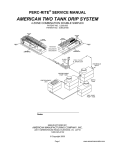
6.2. Explanation – Host Unit Expansion Cards
The RadioNet system has been design to be incorporated into existing irrigation controllers that don’t have the
features of wireless control and monitoring. We call the Parallel Controller Mode. To use this mode, there are 2
optional expansion cards that maybe inserted inside the Host Unit.
48 x Parallel Input Card
48 x Output Card (for input status playback)
The Input Card has been designed to except the wet voltage supplied from the Parallel Controller’s outputs and
transfer this information to a remote RadioNet RTU. Refer to Fig. 6.2a below.
The Output Card has been designed to playback the remote input status back into the Parallel Controllers input circuit.
Refer to Fig. 6.2c below
Both cards maybe installed inside the Host Unit to offer both input and output features at the same time. Refer to fig.
6.2b below
Fig. 6.2a
Fig. 6.2b
Doc. Name: RadioNet - User Manual
Fig. 6.2c
Revision: 01
Crop Management Technologies
Page: - 46 - of 98 pages
USER MANUAL
RadioNet
6.3. Configuration – Host Unit Expansion Card, 48 Parallel Inputs
Prior to performing configuration settings for the Parallel Controller, confirm that you have performed a successful
capture from the Host unit.
Note:
This feature requires the 48 Parallel Input card to be inserted inside the Host Unit. (Part # 00035-008330) (Board # 163)
Step 1 Connect communication cable between PC and Host unit, start PoleNet PC software, configure connection
and connect. (refer chapter 4.2)
Step 2 Access Agile Host – Select control mode
2.1
Select “Select control mode” button
Step 3 Select control mode “Parallel Controller” for correct Host unit operation
3.1
3.2
Select the “Parallel Controller” from the selection list
Select the “Okay” button to confirm selection
Step 4 Select “Configure Controller” button
Doc. Name: RadioNet - User Manual
Revision: 01
Crop Management Technologies
Page: - 47 - of 98 pages
USER MANUAL
RadioNet
Step 5
5.1
5.2
5.3
5.4
Mapping of Parallel Controller address to Remote address
Complete RadioNet Host to Parallel Controller Mapping Form (Example located in Annex D)
Complete mapping data
Save a backup copy
Program Host
Read/Program
Host
Load/Save
Backup File
Outputs Tabs
Exit Screen
Controller I/O
Common
Name
Mapped
Remote
Address
Captured and
Available
Remote
Address
Clear Screen
Settings
Change View
“Changed View”
Captured and
Available
Elements
Contract Data
View
Mapped
Element
Expand Data
View
Change View
Doc. Name: RadioNet - User Manual
Revision: 01
Crop Management Technologies
Page: - 48 - of 98 pages
USER MANUAL
RadioNet
6.3.1. Mapping of Parallel Controller Input Address Settings Definitions
Read:
Selecting the “Read” button with upload the mapping information currently stored in the Host unit.
Program:
Selecting the “Program” button with download the current mapping information and store it into the Host unit’s
memory. You will receive a warning pop-up at the completion of a successful download.
Load:
Selecting the “Load” button open a browse window which will enable you the locate a previously saved Parallel
Controller Address settings
Save:
Selecting the “Save” button open a browse window which will enable you to locate a suitable location where you can
save a backup copy of your Parallel Controller Address settings.
Doc. Name: RadioNet - User Manual
Revision: 01
Crop Management Technologies
Page: - 49 - of 98 pages
USER MANUAL
RadioNet
Outputs Tabs:
Selecting the Outputs Tabs displays the settings screen for the Outputs view.
I/O Number:
Selected I/O
Number
Text Box
Scroll Bar
Selection can be made by using the scroll bar and highlighting the required I/O number of the Parallel Controller
(identified by blue marker) or typing in required I/O number into text box and then selecting the I/O number of the
Parallel Controller.
Name:
This is a read only screen which displays the current address of the Parallel Controller I/O.
Outputs Activated:
Move selected
Free elements
to Activated
Column
Move selected
Activated
elements to
Free Column
The “Activated” column displays the list of current remote I/O Address’s that have been assigned to the Parallel
Controller I/O address. The number adjacent to the column heading (circled in red above) displays the total number of
outputs assigned to the activated column.
Selection is made by highlighting the required remote element from the Free Column and then selecting the move left
button to move the selection to the activated column. The reverse process can also be made when the other move
right button is selected.
Doc. Name: RadioNet - User Manual
Revision: 01
Crop Management Technologies
Page: - 50 - of 98 pages
USER MANUAL
RadioNet
Free Outputs:
Move selected
Free elements
to Activated
Column
Move selected
Activated
elements to
Free Column
The “Free” column displays the list of captured remote I/O Address’s that are available to be mapped to the Parallel
Controller I/O address. The number adjacent to the column heading (circled in red above) displays the total number of
outputs that have not yet been mapped to the Parallel Controller Address.
Selection is made by highlighting the required remote element from the Free Column and then selecting the move left
button to move the selection to the activated column. The reverse process can also be made when the other move
right button is selected.
Clear Settings:
Selecting the Clear Settings button will clear all mapped data in the Host unit. You will see that all the elements in the
“Activated” column will return to the “Free” Column.
Change View:
Selecting the “Change View” button will display both the input and output mapping data as viewed from the Remote
units hardware point of view.
Doc. Name: RadioNet - User Manual
Revision: 01
Crop Management Technologies
Page: - 51 - of 98 pages
USER MANUAL
RadioNet
6.4. Configuration – Host Unit Expansion Card, 48 Output (Input Playback)
Prior to performing configuration settings for the Parallel Controller, confirm that you have performed a successful
capture from the Host unit.
Note:
This feature requires the 48 Parallel Input card to be inserted inside the Host Unit. (Part # 00035-008340) (Board # 239)
Step 1 Connect communication cable between PC and Host unit, start PoleNet PC software, configure connection
and connect. (refer chapter 4.2)
Step 2 Access Agile Host – Select control mode
2.1
Select “Select control mode” button
Step 3 Select control mode “Parallel Controller” for correct Host unit operation
3.1
3.2
Select the “Parallel Controller” from the selection list
Select the “Okay” button to confirm selection
Step 4 Select “Configure Controller” button
Doc. Name: RadioNet - User Manual
Revision: 01
Crop Management Technologies
Page: - 52 - of 98 pages
USER MANUAL
RadioNet
Step 5
5.1
5.2
5.3
5.4
Mapping of Parallel Controller address to Remote address
Complete RadioNet Host to Parallel Controller Mapping Form (Example located in Annex D)
Complete mapping data
Save a backup copy
Program Host
Read/Program
Host
Load/Save
Backup File
Inputs Tabs
Exit Screen
Controller I/O
Common
Name
Mapped
Remote
Address
Captured and
Available
Remote
Address
Clear Screen
Settings
Change View
“Changed View”
Mapped
Element
Contract Data
View
Captured and
Available
Elements
Expand Data
View
Change View
Doc. Name: RadioNet - User Manual
Revision: 01
Crop Management Technologies
Page: - 53 - of 98 pages
USER MANUAL
RadioNet
6.4.1. Mapping of Parallel Controller Output Address Settings Definitions
Read:
Selecting the “Read” button with upload the mapping information currently stored in the Host unit.
Program:
Selecting the “Program” button with download the current mapping information and store it into the Host unit’s
memory. You will receive a warning pop-up at the completion of a successful download.
Load:
Selecting the “Load” button open a browse window which will enable you the locate a previously saved Parallel
Controller Address settings
Save:
Selecting the “Save” button open a browse window which will enable you to locate a suitable location where you can
save a backup copy of your Parallel Controller Address settings.
Doc. Name: RadioNet - User Manual
Revision: 01
Crop Management Technologies
Page: - 54 - of 98 pages
USER MANUAL
RadioNet
Inputs Tabs:
Selecting the Inputs Tabs displays the settings screen for the Inputs view.
I/O Number:
Selected I/O
Number
Text Box
Scroll Bar
Selection can be made by using the scroll bar and highlighting the required I/O number of the Parallel Controller
(identified by blue marker) or typing in required I/O number into text box and then selecting the I/O number of the
Parallel Controller.
Name:
This is a read only screen which displays the current address of the Parallel Controller I/O.
Inputs Activated:
Move selected
Free elements
to Activated
Column
Move selected
Activated
elements to
Free Column
The “Activated” column displays the list of current remote I/O Address’s that have been assigned to the Parallel
Controller I/O address. The number adjacent to the column heading (circled in red above) displays the total number of
outputs assigned to the activated column.
Selection is made by highlighting the required remote element from the Free Column and then selecting the move left
button to move the selection to the activated column. The reverse process can also be made when the other move
right button is selected.
Doc. Name: RadioNet - User Manual
Revision: 01
Crop Management Technologies
Page: - 55 - of 98 pages
USER MANUAL
RadioNet
Free Inputs:
Move selected
Free elements
to Activated
Column
Move selected
Activated
elements to
Free Column
The “Free” column displays the list of captured remote I/O Address’s that are available to be mapped to the Parallel
Controller I/O address. The number adjacent to the column heading (circled in red above) displays the total number of
inputs that have not yet been mapped to the Parallel Controller Address.
Selection is made by highlighting the required remote element from the Free Column and then selecting the move left
button to move the selection to the activated column. The reverse process can also be made when the other move
right button is selected.
Clear Settings:
Selecting the Clear Settings button will clear all mapped data in the Host unit. You will see that all the elements in the
“Activated” column will return to the “Free” Column.
Change View:
Selecting the “Change View” button will display both the input and output mapping data as viewed from the Remote
units hardware point of view.
Doc. Name: RadioNet - User Manual
Revision: 01
Crop Management Technologies
Page: - 56 - of 98 pages
USER MANUAL
RadioNet
7.
Diagnostics & Trouble Shooting Guide
We realize that when you working with wireless control, you are working with a medium that is invisible, difficult to
understand at the best of times and there are no simple tools that you can use such as a pressure gauge or multimeter. Netafim developed the RadioNet and PoleNet PC software with this in mind.
The PoleNet PC software provides you will the necessary tools to test and diagnose a wide range of faults that you
are most likely to come across whilst dealing with wireless communications.
Doc. Name: RadioNet - User Manual
Revision: 01
Crop Management Technologies
Page: - 57 - of 98 pages
USER MANUAL
RadioNet
7.4. Diagnostics – Host
7.4.1. Host Diagnostics – Hardware
This page intentionally left blank
Doc. Name: RadioNet - User Manual
Revision: 01
Crop Management Technologies
Page: - 58 - of 98 pages
USER MANUAL
RadioNet
This page intentionally left blank
Doc. Name: RadioNet - User Manual
Revision: 01
Crop Management Technologies
Page: - 59 - of 98 pages
USER MANUAL
RadioNet
7.4.2. Host Unit Diagnostics – Software
Step 1 Connect communication cable between PC and Host unit, start PoleNet PC software, configure connection
and connect. (refer chapter 4.2)
Step 2 Access Agile Host – Monitor
2.1
Select Monitor button
7.4.2.1.
Host Unit Diagnostics - Networks
The monitor window provides an overview of the complete RadioNet system as viewed from the Host unit and
Base unit. Prior to configuring the Host unit, we need to make sure that the route map data that has been
entered into the base is also viewed correctly via the Host unit.
The screen is divided into 2 main sections.
The top portion of the display is Global System Information as viewed from the Host unit and Base unit, while
the bottom portion displays information relating to tab selected, in this example the Tab Data displays the
available networks.
Global System
Information
Network Tab
Tab Data
Close Button
Doc. Name: RadioNet - User Manual
Revision: 01
Crop Management Technologies
Page: - 60 - of 98 pages
USER MANUAL
RadioNet
7.4.2.2.
Listed:
Definitions of Host Monitor Mode – Networks Tab
Displays the total number of devices (networks, units, I/O) that is theoretically available to both
the Host unit and the Base unit.
Note:
Note:
The Base Radio is included as both a network and as a unit.
The quantity of units is derived from the base plus the numbers of units defined in the route map.
Present:
Displays the total number of active devices (networks, units, I/O) that are currently connected to
the Host unit and the Base unit, either physically or via the wireless network.
Missing:
Displays the total number of devices (networks, units, I/O) that the Host unit or Base unit has
not currently made a connection with.
Extra:
Displays the total number of devices (networks, units, I/O) as defined in the Host unit and Base
unit that has not been captured.
On:
Displays the total number of digital inputs and digital outputs that are currently ON within the
system
Network Tab:
Displays the status of the networks that are accessible
Units Tab:
Displays the status of the defined units, both Base units and Remotes units that are accessible
Routing Tab:
Displays both the network configuration and routing configuration as seen by both the Host unit
and Base unit.
Doc. Name: RadioNet - User Manual
Revision: 01
Crop Management Technologies
Page: - 61 - of 98 pages
USER MANUAL
RadioNet
7.4.2.3.
Host Unit Diagnostics - Base & Remote Units
The monitor window provides a status overview of the Base unit and Remote units as viewed from the Host
unit and Base unit. Status information includes network, mapping, routing, signal strength, battery voltage,
battery condition, unit temperature and firmware version.
Global System
Information
Units Tab
Tab Data
Close Button
7.4.2.4.
Definitions of Host Monitor Mode – Units Tab
Unit:
Displays the Electronic Serial Number (ESN) of all the units that have been configured in the
route map.
Net:
Displays which network the unit belongs too.
Present:
Displays the current status of the unit, whether the unit is on-line or off-line.
No
=
Unit is off-line
Yes
=
Unit is on-line & available
Extra:
Displays the current status of the unit, whether the unit is available, or has not yet been
captured.
No
=
Unit has been captured
Yes
=
Unit has not been captured
Routed:
Displays the current status of the unit, whether the unit is on-line or off-line. When the unit is online, several conditions may exist.
Missing =
Unit is off-line
Yes
=
Unit is on-line & available
Orphan =
Unit that has been adopted in the aloud list of the base (old route map), but
not included in the new route map
Rogue =
Unit that has been adopted by the Host (old route map) and is not on the
allowed list of the base.
Note:
If you see Orphan’s or Rogue’s, a Host reset should be performed.
Doc. Name: RadioNet - User Manual
Revision: 01
Crop Management Technologies
Page: - 62 - of 98 pages
USER MANUAL
RadioNet
State:
Displays the status of the unit.
Absent
=
Unit is off-line
Get I/O Cal
=
Unit is on-line & uploading I/O information
Set Mode
=
Unit is on-line & comm. mode is being set
Normal
=
Unit is on-line
Progress:
Displays the unit’s progress as it is coming on-line.
0%
=
Unit is off-line
100%
=
Unit is on-line & available
SAF Route:
Displays the remotes unit’s communication path via a Store and Forward (SAF) Repeater unit,
which is also known as it’s Master.
RSSI:
Displays the received signal strength from the view point of the remote unit.
IE: the received signal strength from the remote unit’s master.
Vbatt:
Displays the current battery voltage in the remote unit.
EG: 6.543V
Batt:
Displays the remote unit’s battery condition.
Ok
=
Battery okay
Warn
=
Battery warning, normal charge can’t be maintained
Low
=
Battery voltage getting low, urgent action required
Fail
=
Battery voltage is very low, unit has turned off the digital outputs and radio
and is now in hibernation.
Temperature:
Displays the current internal temperature of the radio board.
Time of Data:
Displays the time and data of the last status transmission generated from the remote unit.
FW:
Displays the unit’s current firmware.
Drops:
Displays the number of communication drops
Note:
Note:
A drop is considered when the remote unit has not replied to the base within 8 communication cycle times.
Drops are only counted while the PoleNet is active.
Doc. Name: RadioNet - User Manual
Revision: 01
Crop Management Technologies
Page: - 63 - of 98 pages
USER MANUAL
RadioNet
Advanced Mode
Select the “Test” button to activate the diagnostic mode. Right mouse button selection on the
required emote unit will activate a diagnostic pop-up window.
Note:
Refer to setting advanced mode user guide in section 5.5
Poll:
A forced communication can be initiated with the remote unit within the next cycle time.
Get RSSI:
A forced communication, requesting the RSSI will be initiated with the remote unit within the
next cycle time.
Get Battery Voltage: A forced communication, requesting the current battery voltage will be initiated with the remote
unit within the next cycle time.
Get Temperature:
A forced communication, requesting the current temperature will be initiated with the remote
unit within the next cycle time.
Doc. Name: RadioNet - User Manual
Revision: 01
Crop Management Technologies
Page: - 64 - of 98 pages
USER MANUAL
RadioNet
7.4.2.5.
Host Unit Diagnostics - Digital Inputs
The monitor window provides a status overview of all the digital inputs as viewed from the Host unit and Base
unit. Status information includes whether the digital input is on-line or off-line, captured and mapped, current
status and pulse count.
Global System
Information
Dig Ins Tab
Filter
Tab Data
Close Button
7.4.2.6.
Address:
Definitions of Host Monitor Mode – Dig Ins Tab
Displays the network address followed by the units Electronic Serial Number (ESN) including
the physical address of the digital input.
Note:
Refer to Annex B regarding digital output location.
Present:
Displays the current status of the digital input, whether the input is on-line or off-line.
No
=
Digital Input is off-line
Yes
=
Digital Input is on-line & available
Extra:
Displays the current status of the digital input, whether the input is available, or has not yet
been captured.
No
=
Digital Input has been captured
Yes
=
Digital Input has not been captured
Mapped:
Displays the current mapping status of the digital output.
No
=
Digital input has not been mapped
Yes
=
Digital input has been mapped
State:
Displays the status of the digital input as confirmed by the remote unit.
1
=
Input is confirmed “ON” by the Remote
No Data =
Input is confirmed “OFF” by the Remote
Count:
Displays the number of pulses counted by the remote
Note:
The pulse count is incremented on the trialing edge of the pulse
IE: when the digital input turns off.
Doc. Name: RadioNet - User Manual
Revision: 01
Crop Management Technologies
Page: - 65 - of 98 pages
USER MANUAL
RadioNet
7.4.2.7.
Host Diagnostics - Digital Outputs
The monitor window provides a status overview of all the digital outputs as viewed from the Host unit and
Base unit. Status information includes whether the digital output is on-line or off-line, captured and mapped,
current status and important information about digital output failures such as open and short circuit detection.
Global System
Information
Dig Outs Tabs
Filter
Tab Data
Close Button
7.4.2.8.
Address:
Definitions of Host Monitor Mode – Dig Outs Tab
Displays the network address followed by the units Electronic Serial Number (ESN) including
the physical address of the digital output.
Note:
Present:
Displays the current status of the digital output, whether the output is on-line or off-line.
No
Yes
Extra:
=
=
Unit is off-line
Unit is on-line & available
Displays the current status of the digital output, whether the output is available, or has not yet
been captured.
No
Yes
Mapped:
Refer to Annex B regarding digital output location.
=
=
Unit has been captured
Unit has not been captured
Displays the current mapping status of the digital output.
No
Yes
=
=
Digital output has not been mapped
Digital output has been mapped
Doc. Name: RadioNet - User Manual
Revision: 01
Crop Management Technologies
Page: - 66 - of 98 pages
USER MANUAL
RadioNet
State:
Displays the status of the digital output as confirmed by the remote unit.
On
Off
Information:
=
=
Output is confirmed “active” by the Remote
Output is confirmed “idle” by the Remote
Displays the operational command and status of the digital output.
Change to 1
Change to 0
Override:
Faulty O/C
=
=
=
=
Faulty S/C
=
An “ON” command has been sent to Remote
An “OFF” command has been sent to Remote
Output manually activated.
Output has sensed no current draw IE: there is no solenoid or relay
attached and circuit is open
Output has sensed excessive current draw and determined that the
output circuit is shorted.
Doc. Name: RadioNet - User Manual
Revision: 01
Crop Management Technologies
Page: - 67 - of 98 pages
USER MANUAL
RadioNet
7.4.2.9.
Host Unit Diagnostics - Routing
The routing window provides an overview of the complete RadioNet system as viewed from the Host unit and
Base unit.
This information is derived from the route map that has been programmed into the Base units memory.
The RadioNet Technician should confirm that the data displayed in the routing screen is identical to the site
map which has been compiled earlier.
Note:
Note:
Please confirm that the Host has been reset since the Route Map was downloaded into the Base.
Please allow up to 45 seconds after Host unit resets.
Global System
Information
Routing Tab
Contract Data
SAF Unit
Tab Data
Expand Data
SAF Unit
Close Button
Doc. Name: RadioNet - User Manual
Revision: 01
Crop Management Technologies
Page: - 68 - of 98 pages
USER MANUAL
RadioNet
7.4.2.10.
Host Unit Diagnostics - System
The system window provides an overview of the complete RadioNet system as viewed from the Host unit and
Base unit.
This information is derived from the route map, captured data and I/O mapping.
Valuable information is displayed showing the connection from the mapped I/O through to network 1.
Note:
Note:
Please confirm that the Host has been reset since the Route Map was downloaded into the Base.
Please allow up to 45 seconds after Host unit resets.
Global System
Information
System Tab
Filter
Contract Data
Tab Data
Expand Data
Close Button
Doc. Name: RadioNet - User Manual
Revision: 01
Crop Management Technologies
Page: - 69 - of 98 pages
USER MANUAL
RadioNet
7.5. Diagnostics – Base Unit
7.5.1. Base Unit Diagnostics – Hardware
Step 1 Identify location of the 2 diagnostic LEDs.
202 LED #1
(Receive)
209 LED #1
(Transmit)
Step 2 Power up Base
Confirm that 202 LED #1 (Receive) flashes quickly (approximately 12 times)
The flashing LED acknowledges that the unit is powered up correctly and has passed its internal shelf
checks.
209 LED #1 (Transmit) will illuminate every time the Base Radio has a requirement to transmit
202 LED #1 (Receive) will illuminate every time the Base Radio hears RadioNet data.
Note: 202 LED #1 is disabled when PC connection is made.
Doc. Name: RadioNet - User Manual
Revision: 01
Crop Management Technologies
Page: - 70 - of 98 pages
USER MANUAL
RadioNet
7.5.2. Base Unit Diagnostics – Software
PoleNet PC Software can be used to connect directly to the communication port of the Base unit. When
selecting the monitor function, a range of functions are monitored, such as route map, allowed units, cards,
battery voltage, and internal temperature of base radio.
Step 1 Connect communication cable between PC and base unit, start PoleNet PC software, configure connection
and connect. (refer Chapter 4.3)
Step 2 Access RadioNet – Base Monitoring Mode
2.1
Select Monitor Button
Step 4
Select “Route” Tab
The list displays the current number of digital inputs and digital outputs that correlates to the number
and type of hardware that is connected and functional.
Total number
of Units in
Route Map
Tabs
Cycle Time in
Seconds
Expand Data
SAF Unit
Units in
Network
Structure
Contract Data
SAF Unit
Battery
Voltage
Temperature
Doc. Name: RadioNet - User Manual
Revision: 01
Crop Management Technologies
Page: - 71 - of 98 pages
USER MANUAL
RadioNet
7.5.2.1.
Definitions of Radio Base Monitor – Route Tab
Route:
Displays the Route Map, including the network cycle time and the structure of the Network
Allowed Units:
Physical Address of the I/O available.
This Address will be used for mapping of the RadioNet I/O to the Master Controllers I/O.
Cards:
Displays the current configuration of cards installed in the base unit
Ins & Outs:
Not used
# Remotes:
Displays the total number of remote units as defined in the route map.
Battery:
Displays the current configuration of cards installed in the base unit
RSSI:
Not used
Temperature:
Displays the current temperature of the internal base radio board
Close:
Exits the radio monitor screen
Doc. Name: RadioNet - User Manual
Revision: 01
Crop Management Technologies
Page: - 72 - of 98 pages
USER MANUAL
RadioNet
7.5.2.2.
Allowed Units:
Definition of Radio Remote Monitor – Allowed Units Tab
The “Allowed Units” list allows the remote units to join this network. Should a remote unit with
the same frequency be heard by the Base Radio, it will be ignored.
Doc. Name: RadioNet - User Manual
Revision: 01
Crop Management Technologies
Page: - 73 - of 98 pages
USER MANUAL
RadioNet
7.5.2.3.
Card:
Definition of Radio Remote Monitor – Cards Tab
The card number represents the card position.
Note:
Type:
The card type number represents that type of card which has been installed in this location.
Note:
ESN:
Refer to Annex B for card position number
Refer to Annex C for Card Type Number
The Electronic Serial Number (ESN) of the card which has been installed in this location.
Doc. Name: RadioNet - User Manual
Revision: 01
Crop Management Technologies
Page: - 74 - of 98 pages
USER MANUAL
RadioNet
7.6. Diagnostics – Remote Unit
7.6.1. Remote Unit Diagnostics – Hardware
Step 1 Check wiring, confirm wiring of the power circuit prior to connection.
Step 2 Identify location of push button (PB) and diagnostic LED.
Push Button
Diagnostic
Led
Note: Both the Push Button and the Diagnostic LED are located on the lower printed circuit board, adjacent to the RJ 45 Communication
connector, located on the left hand side.
Step 3 Power up remote
Confirm that Red LED #1 Flashes quickly (approximately 12 times)
The flashing LED acknowledges that the unit is powered up correctly and has passed it’s internal shelf
checks.
Note: LED is disabled when PC connection is made
Note: LED may flash quickly after remote reset from Base is performed.
Step 4 Push Button Diagnostics
When the push button is pressed and released, the diagnostic LED will flash slowly, the number of flashes
counted will determine the status level of the RadioNet Remote Unit.
STATUS LEVEL
1
2
3
4
DIAGNOSTIC DESCRIPTION
Unit is okay, battery voltage okay, digital outputs are okay, and remote unit is
on the network.
Unit is not okay, battery voltage is below the “good” threshold level.
Problem with one or more of the digital outputs. Possible cause would be an
open or short circuit on one or more digital outputs.
Remote unit is not currently on the network.
Note: A status level 2 overrides a level 3 and a level 3 overrides a level 4.
Doc. Name: RadioNet - User Manual
Revision: 01
Crop Management Technologies
Page: - 75 - of 98 pages
USER MANUAL
RadioNet
7.6.2. Remote Unit Diagnostics – Software
PoleNet PC Software can be used to connect directly to the communication port of the Remote unit. When
selecting the monitor function, a range of functions are monitored, such as digital inputs, digital outputs,
battery voltage, signal strength and internal temperature of the Remote units radio.
Step 1 Connect communication cable between PC and Remote unit, start PoleNet PC software, configure connection
and connect. (refer chapter 4.4)
Step 2
Step 2.1
Access RadioNet – Remote Monitoring Mode
Select Monitor Button
Step 4
Select “Ins & Outs” Tab
The list displays the current number of inputs and outputs that correlates to the number and type of
hardware that is connected and functional.
Tabs
Column
Headings
I/O
Number
Digital Output
Status
Battery
Voltage
Temperature
Test
Button
Signal
Strength
Close
Button
Doc. Name: RadioNet - User Manual
Revision: 01
Crop Management Technologies
Page: - 76 - of 98 pages
USER MANUAL
RadioNet
7.6.2.1.
Definition of Radio Remote Monitor – Ins & Outs Tab
IO:
Logical Input/Output number available
As the I/O expansion cards are plug & play, the I/O number will only appear when the I/O card
is inserted and recognized.
Addr:
Physical Address of the I/O available.
This Address will be used for mapping of the RadioNet I/O to the Host Controllers I/O.
State:
Current status of the Input/Output.
Inputs:
0 = OFF (open circuit)
Outputs:
0 = OFF (closed/idle)
Count:
1 = ON (closed circuit)
1 = ON (open/active)
Total number of inputs (pulses) counted
Note: Input counted from trailing edge of pulse.
Information:
Status of the command or state
Override:
Output manually activated.
Faulty O/C:
Output detected that there is no solenoid or relay connected.
Faulty S/C:
Output detected that there is a Short Circuit.
Battery:
Current battery voltage level sensed by the Remote Unit
RSSI:
Return Signal Strength Indicator displayed in dBm.
This is the signal strength recorded coming from the Master of this remote unit.
IE: the received signal strength.
Note:
If the remote has no master, then the RSSI value represents the noise floor.
Temperature:
The current temperature reported of the internal radio board.
Test Button:
Selecting the Test Button puts the units in testing mode.
Right mouse click on the DO number will activate a manual command list “On” or “Off”, giving
the operator the option to manually activate the digital output.
Note:
Note:
Manual operation temporary overrides the Host Controllers operation and may generate a Master
Controller Alarm.
Closing the “Testing” button will automatically close any manually opened digital outputs.
Doc. Name: RadioNet - User Manual
Revision: 01
Crop Management Technologies
Page: - 77 - of 98 pages
USER MANUAL
RadioNet
Step 5
7.6.2.2.
Card:
Select Cards Tab
The list displays the current number of cards that correlates to the number and type of hardware
that is connected and functional.
Definition of Radio Remote Monitor – Cards Tab
The card number represents the card position.
Note:
Type:
Refer to Annex B for card position number
The card type number represents that type of card which has been installed in this location.
Note:
Refer to Annex C for Card Type Number
ESN:
The Electronic Serial Number (ESN) of the card which has been installed in this location.
Close Button:
Closes the Monitor screen of PoleNet.
Doc. Name: RadioNet - User Manual
Revision: 01
Crop Management Technologies
Page: - 78 - of 98 pages
USER MANUAL
RadioNet
8.
Surveyor Mode
Designing a reliable wireless control system requires a very good understanding of local factors such as:
Location
Existing atmospheric noise and interfering signals
Topography
Distance
Foliage
Climate
Project boundaries
Whilst some of these parameters can be calculated using theoretical data, there is no substitute for practical
measurements for real results.
Each RadioNet Remote unit has special built-in firmware to enable it to act in special modes to perform site surveyor
tests.
8.4. Surveyor Mode - RSSI Floor
The RSSI Floor test mode is used to determine how noisy the project site is at the nominated operating frequency.
The results will provide you with an understanding of the amplitude and duration of the recorded noise levels.
Results
Window
Sample
Window
Measure
Button
Note:
Make sure your test unit has a good antenna at an equivalent height and proximity to the project being investigated, otherwise a poor
antenna will give you artificial, better than actual results.
Step 1
Connect communication cable between PC and Remote unit, start PoleNet PC software, configure
connection and connect. (refer chapter 4.5)
Step 2
To start the RSSI Floor test, select the “Measure” button
Note:
RSSI Floor test operates for approximately 1 second. To repeat test, pressure the “Measure “ button again.
Doc. Name: RadioNet - User Manual
Revision: 01
Crop Management Technologies
Page: - 79 - of 98 pages
USER MANUAL
RadioNet
8.4.1. Definition of Radio Surveyor Mode – RSSI Floor Tab
Results Window:
The “Results Window” displays the average noise level received at the time of performing the test. The Surveyor unit
then provides a recommendation of approximately 6dB greater than the average RSSI floor recorded when performing
the interference mode test.
Sample Window:
Noise
Strength
When the remote unit performs the RSSI Floor test, the unit listens for RF signals and records the strength, number of
pulses and the percentage of time that the noise was heard. It then displays the samples taken.
Figure 9.1 below shows graphically what the results would look like if transposed onto a graph. The test only lasts for
1 second, giving you a snapshot of the RSSI noise floor. The atmospheric noise has been recorded as -111 dBm in
this example. A good result would see the noise floor no greater than -6dBm below the reported RSSI of your Remote
units.
Figure 8.1
Measure Button:
When selected, the unit will perform a RSSI Floor test by listening and recording the RF environment at the preprogrammed frequency for approximately 1 second.
Doc. Name: RadioNet - User Manual
Revision: 01
Crop Management Technologies
Page: - 80 - of 98 pages
USER MANUAL
RadioNet
8.5. Surveyor Mode – Interference
The purpose of the interference mode test is to listen and record any interfering RF signal over a larger period of time.
The Interference test mode should follow on from the RSSI floor test, where the technician can set the minimum limit
to ignore unwanted RF signals. As RF interference is not always consistent, it’s best to listen over a larger period of
time to obtain an accurate result.
Results
Window
Data
Filters
Data
Samples
Window
Test
Threshold
Start Test
Button
Stop Test
Button
This test doesn’t record the amplitude of the interfering RF signals but the number and period of the pulses that
exceed the programmed threshold limit. In the example given above, the threshold has been set to -105 dBm. Figure
8.2 below shows graphically, what the results would look like if transposed onto a graph. This example shows that
interfering RF signals do exist at this site at the test frequency.
Figure 8.2
Step 1
Connect communication cable between PC and Remote unit, start PoleNet PC software, configure
connection and connect. (refer chapter 4.5)
Step 2
Select the “Interference Tab”
Step 3
To start the Interference test, select the “Start” button
Note:
To perform this test over extended periods, simply select the “Close” button and the test mode will stay active.
Step 3
To stop the Interference test, select the “Stop” button
Doc. Name: RadioNet - User Manual
Revision: 01
Crop Management Technologies
Page: - 81 - of 98 pages
USER MANUAL
RadioNet
8.5.1.1.
Definition of Radio Surveyor Mode – Interference Tab
CS Power Threshold:
The “CS Power Threshold” defines the level in which atmospheric noise and interfering RF signals will be recorded.
IE: Only signals which are stronger than -105 dBm will be counted. The user has the option to use the recommended
value as calculated during the RSSI Floor test or define a user specified threshold.
Note: If using specified threshold level, the maximum level is limited to -84 dBm.
Start:
When selected, the Interference test is initiated, constantly sampling the airways in 5 second groups.
Note: If the interference test is to run over extended periods of time, even days, then simply close the screen, disconnect the unit and it will
continue with the interference test.
Stop:
When selected, the Interference test will stop
Results Window:
The results window displays the accumulative results since the test was first stated. The unit samples and
accumulates results every 5 seconds.
Example:
Signal threshold was set to -102 dBm, the test has been running for a total of 7015 seconds, 112 pulses were
recorded above the threshold setting, totaling 55.2 seconds, which overall, relates to 0% interference duty cycle.
Note: If no interfering signal was recorded, you will not see information in the data samples window.
Doc. Name: RadioNet - User Manual
Revision: 01
Crop Management Technologies
Page: - 82 - of 98 pages
USER MANUAL
RadioNet
Show Long Term:
Data
Samples
Window
When selected, the data sample window displays the longer term results. IE: Only the periods of time when RF
interference was recorded above the threshold setting.
Show Totals:
Data
Samples
Window
When selected, the data sample window displays the accumulative total results, both the number of pulses and the
total time that the RF interference was recorded above the threshold setting.
Example:
At 14:50, a total of 96 pulses with a total combined time of 34.9 seconds was recorded above the
threshold (-102dBm).
Show Blank Lines:
Data
Samples
Window
When selected, the data sample window displays the results for every 5 second period. Should that period sense
interference, both the number of pulses and the duration of the pulses will be recorded.
Doc. Name: RadioNet - User Manual
Revision: 01
Crop Management Technologies
Page: - 83 - of 98 pages
USER MANUAL
RadioNet
8.6. Surveyor Mode - Channel Quality
The Channel Quality test mode is used to determine the integrity of the communication path between the base unit
and remote sites. We also call this a range test. Only two Remote units are required to perform this test, together with
a laptop and PoleNet PC software.
Typically 1 unit (termed the Base) is installed at either the base site or a repeater site, the other unit (termed the
Remote) is moved from remote site to remote site to perform the required tests. The test antenna’s used should
represent as close as possible the type and height of the antenna’s that would typical be used for the type of project
under test.
The test performed records both the signal strength and the signal quality. The signal strength is displayed in dBm and
the signal quality displays the bit error rate (BER). Both results are as important as each other, as you should have
good signal strength and no or very low BER results.
8.6.1. Signal Strength.
Signal strength is measured in dB. Decibels (dB) is a logarithmic scale and is expressed as a ratio. In short, -3db is
half (1:2), -10dB is 10 times smaller (1:10) while -20dB is 100 times smaller (1:100).
Please refer to Netafim’s manual on “Introduction to RF” for a more detailed explanation.
Since the receiver sensitivity of the RadioNet is -117dBm and Netafim recommends using a 20dB fade margin for
telemetry applications, a signal strength recorded above -97dBm is considered a good signal for reliable
communications. Should the signal be marginal, between -97dBm and -107dBm, then communications signals will still
be received, but may induce communication retries which introduce communication delays. Signals below -107dBm
are considered poor and unreliable for successful communications.
Figure 8.3
Doc. Name: RadioNet - User Manual
Revision: 01
Crop Management Technologies
Page: - 84 - of 98 pages
USER MANUAL
RadioNet
8.6.2. Bit Error Rate (BER).
When a channel quality test is performed, a known packet of information (1000 data bits) is sent between the 2 test
units. If some of the data is corrupted, then the amount of corrupt data is recorded. This gives you a good
understanding of the quality of the signal path between the two test units.
Column
Headings
Data
Window
Test
Buttons
The example given above shows the results of a poor channel quality test. If we compare the results for the 100mW
test, the base heard the remote ok at -94 dBm, but the signal strength recorded by the remote was marginal at -99
dBm. It was found that the coaxial cable was damaged at the remote site. If we now compare the results at 10mW, we
can see that the BER test started to show errors in the quality of the data being received.
Doc. Name: RadioNet - User Manual
Revision: 01
Crop Management Technologies
Page: - 85 - of 98 pages
USER MANUAL
RadioNet
8.6.2.1.
Definition of Surveyor Mode – Channel Quality Tab
Power Level Test Buttons:
The channel quality test will be initiated when the required transmission power level button is selected. The remote
unit will start by communicating at the highest power level selected, slowly reducing the power levels until the base
unit doesn’t respond. At each power level, data packets are transferred back and forth so the test is performed in both
directions.
Note: Do not perform power tests greater than 10mW without an antenna connected.
mW:
This column represents the power level at which the test was performed.
Base Errors:
This column represents the amount of errors that the base test unit recorded after receiving the data packets from the
remote test unit.
Base dBm:
This column represents the signal strength reported by the base test unit after listening to the remote test unit.
Remote Errors:
This column represents the amount of errors that the remote test unit recorded after receiving the data packets from
the base test unit.
Remote dBm:
This column represents the signal strength reported by the remote test unit after listening to the base test unit.
Doc. Name: RadioNet - User Manual
Revision: 01
Crop Management Technologies
Page: - 86 - of 98 pages
USER MANUAL
RadioNet
9.
Firmware
9.4. Firmware Upgrade Procedure for Remote Unit
Step 1
Step 2
Step 3
Step 4
Step 5
Step 6
Step 7
Step 8
Step 9
Power down Remote Unit
Short program jumper
Connect programming lead
Power up unit (from 6VDC battery supply)
Run command prompt (agileremote_v226 –port com X) (X = active com port Number)
View red LED flashes when communication successful
Wait for message “Program Completed”
Power down
Remove programming jumper
Doc. Name: RadioNet - User Manual
Revision: 01
Crop Management Technologies
Page: - 87 - of 98 pages
USER MANUAL
RadioNet
9.5. Firmware Upgrade Procedure for Base Unit
Step 1
Step 2
Step 3
Step 4
Step 5
Step 6
Step 7
Step 8
Step 9
Power down Base Unit
Short program jumper
Connect programming lead to RF45 on board 202 (Radio Board)
Power up unit (from RS485 lead from Host or 12 VDC power supply)
Host=RS485in
Base=RS485out
Run command prompt (agilebase_v226 –port com X) (X = active com port Number)
View red LED flashes when communication successful (data receive)
Wait for message “Program Completed”
Power down
Remove programming jumper
Doc. Name: RadioNet - User Manual
Revision: 01
Crop Management Technologies
Page: - 88 - of 98 pages
USER MANUAL
RadioNet
9.6. Firmware Upgrade Procedure for Host Unit
Note: Make sure controller communication connections are isolated prior to performing download.
Step 1
Step 2
Step 3
Step 4
Step 5
Step 6
Step 7
Step 8
Step 9
Power down Host Unit (remove 12 VDC plug)
Short program jumper
Connect programming lead
Power up unit (from 12 VDC power supply)
View green LED # 3, continually flashes.
Run command prompt (agilehost_v161 –port com X) (X = active com port Number)
Wait for message “Firmware Upgrade Completed”
Power down
Remove programming jumper
Note: Command prompt is available via the start menu in Windows, select Start, Run, type in CMD and select OK.
Doc. Name: RadioNet - User Manual
Revision: 01
Crop Management Technologies
Page: - 89 - of 98 pages
USER MANUAL
RadioNet
10. Annex A
10.4. Compatible Solenoid & Relay List
Manufacture
Model
Configuration
Wire
Colour
Netafim
Aquative Series 1,
12 VDC Latch Pulse
2
Orange (Open)
Black/White (Close)
Netafim
Aquative Series 2,
9-40 VDC Latch Pulse
2
Orange (Open)
Black/White (Close)
Baccara
Geva 60
12 VDC Latching Pulse
2
Red (Open)
Black (Close)
Bermad
S985
12-50 VDC Latching Pulse
3
Red (Open)
White (Common)
Black (Close)
Bermad
S982
12-50 VDC Latching Pulse
2
Red (Open)
Black (Close)
Bermad
S-392-2
6-40 VDC Latching Pulse
2
Red (Open)
Black (Close)
Izumi
RY2KS
12 VDC Latch Pulse
2
Refer Fig. 10.2
Doc. Name: RadioNet - User Manual
Revision: 01
Crop Management Technologies
Page: - 90 - of 98 pages
USER MANUAL
RadioNet
10.5. Izumi Relay Wiring Schematic
Figure 10.2
Doc. Name: RadioNet - User Manual
Revision: 01
Crop Management Technologies
Page: - 91 - of 98 pages
USER MANUAL
RadioNet
11. Annex B
Figure 11.1
Card position number.
Card Address
2 . 2020000000000109 . 1 . 3
Network #
Remote ESN
Card Location
Doc. Name: RadioNet - User Manual
Position on Card
Revision: 01
Crop Management Technologies
Page: - 92 - of 98 pages
USER MANUAL
RadioNet
Annex B
Figure 11.2
DI position number.
Digital Input Address
DI
DI = Digital Output
4 . 2
4 = Card Location
2 = Position on Card
Doc. Name: RadioNet - User Manual
Revision: 01
Crop Management Technologies
Page: - 93 - of 98 pages
USER MANUAL
RadioNet
Annex B
Figure 11.3
DO position number.
Digital Output Address
DO
DO = Digital Output
4 . 3
4 = Card Location
3 = Position on Card
Doc. Name: RadioNet - User Manual
Revision: 01
Crop Management Technologies
Page: - 94 - of 98 pages
USER MANUAL
RadioNet
12. Annex C
Card Number
Card Description
163
202
207
208
209
219
239
48 x Input Expansion Card for Host
Radio Board
Control Personality Board (Remote)
Expansion Card (2DI, 2DO)
Control Personality Board (Base)
RadioNet Host
48 x Output Expansion Card for Host
Doc. Name: RadioNet - User Manual
Revision: 01
Crop Management Technologies
Page: - 95 - of 98 pages
USER MANUAL
RadioNet
13. Annex D
Fig: 13.1
Example of “RadioNet Host – NMC-Pro Mapping Form”.
Project Name:
RadioNet
Frequency:
Cycle Time:
Backup File Name:
Date:
NMC-Pro
DO #
Example
1
2
3
4
5
6
7
8
9
10
11
12
13
14
15
16
NMC-Pro
DI #
Example
1
2
3
4
5
6
7
8
9
10
11
12
13
14
15
16
Function
#
Remote
ID #
Card
ID #
DO
ID #
Comments
Valve
1
20200110
2
3
located next to block 6B
Function
#
Remote
ID #
Card
ID #
DI
ID #
Comments
Water Meter
1
20200110
1
2
Arad, 1000 Litre Pulse
Doc. Name: RadioNet - User Manual
Revision: 01
Crop Management Technologies
Page: - 96 - of 98 pages
USER MANUAL
RadioNet
Fig: 13.2
Example of “RadioNet Host – Expansion Card Mapping Form”.
Project Name:
RadioNet
Frequency:
Cycle Time:
Backup File Name:
Date:
Host
Function
#
Remote
ID #
Card
ID #
DO
ID #
Comments
Example
1
2
3
4
5
6
7
8
9
10
11
12
13
14
15
16
Valve
1
20200110
2
3
located next to block 6B
Host
Function
#
Remote
ID #
Card
ID #
DI
ID #
Comments
Example
1
2
3
4
5
6
7
8
9
10
11
12
13
14
15
16
Water Meter
1
20200110
1
2
Arad, 1000 Litre Pulse
Doc. Name: RadioNet - User Manual
Revision: 01
Crop Management Technologies
Page: - 97 - of 98 pages
USER MANUAL
RadioNet
14. Glossary
Baud
A data transmission rate (bits/second).
BER
The bit error rate (BER) is the number of bits that have errors relative to the total number of
bits received in a transmission.
Comm.
An abbreviation for “communication”
dBm
dBm (sometimes dBmW) is an abbreviation for the power ratio in decibels (dB) of the
measured power referenced to one milliwatt (mW).
ESN
An abbreviation for “Electronic Serial Number”
ID
An abbreviation for “Identification”
I/O
An abbreviation for “Inputs/Outputs”
LED
An abbreviation for light-emitting diode, which is a small semi-conductor devices that converts
electrical energy into bright light.
mW
A unit of power, milliwatt, which is a unit 1000 times less than a watt
kHz
The hertz (symbol: Hz) is a measure of frequency per unit of time, or the number of cycles per
second. kHz is 1000 Hz.
MHz
The hertz (symbol: Hz) is a measure of frequency per unit of time, or the number of cycles per
second. MHz is 1,000,000 Hz.
NMC
An abbreviation for “Netafim Management Controller”
O/C
An abbreviation for “Open Circuit”
PB
An abbreviation for “Push Button”
PC
An abbreviation for “Personal Computer”
RF
An abbreviation for “Radio Frequency”
RSSI
Received Signal Strength Indication (RSSI) is a measurement of the power present in a
received radio signal
SAF
An abbreviation for “Store And Forward”, more commonly known as a repeater
S/C
An abbreviation for “Short Circuit”
USB
Universal Serial Bus (USB) is a serial bus standard to interface devices to a host computer
VDC
Voltage Direct Current. The voltage measurement in a DC system
Doc. Name: RadioNet - User Manual
Revision: 01
Crop Management Technologies
Page: - 98 - of 98 pages