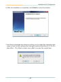
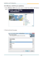
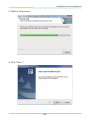
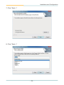
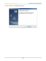
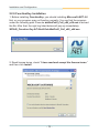
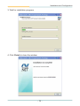
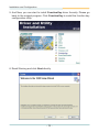
1
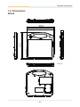
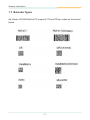
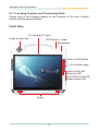
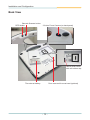
M1040
10.4" Intel® AtomTM N450
Mobile Clinical Assistant
User's Manual
Version 1.1
P/N: 4012104000110P
2011.10
This page is intentionally left blank.
Index
Contents
Copyright Notice.............................................................................................. i
Declaration of Conformity.............................................................................. i
About This User's Manual............................................................................ iii
Technical Support......................................................................................... iii
Important Safety Instructions....................................................................... iv
Classification.................................................................................................. v
Disposing of Your Old Product..................................................................... v
General Cleaning Tips................................................................................... vi
Introducing the Rechargeable Battery Pack.............................................. vii
Symbols Description................................................................................... viii
Warranty......................................................................................................... ix
Chapter 1 - General Information.................................................................... 1
1.1 Introduction........................................................................2
1.2 Packing List........................................................................3
1.3 Ordering Information.........................................................3
1.4 Specifications.....................................................................4
1.5 Power Information..............................................................5
1.6 Dimensions.........................................................................6
1.7 Barcode Types....................................................................7
Chapter 2 - Installation and Configuration................................................... 9
2.1 Getting Started.................................................................10
2.1.1 Locating Controls and Connecting Ports........... 11
2.1.2 Replacing the External Battery............................15
2.1.3 Installation.............................................................17
2.1.4 Introducing the M1040 Docking Station.............22
2.1.5 Installing the M1040 on the Docking Station.....26
2.1.6 Removing the M1040 from the Docking Station.28
2.1.7 Charging via the Docking Station.......................29
2.1.8 Connecting with the Peripheral Devices............30
2.1.9 VESA Wall-mounting (75 x 75).............................34
2.1.10 Install Hand Strap...............................................35
2.1.11 Introducing the M1040 Desktop Cradle............37
2.1.12 Installing the M1040 on the Desktop Cradle....41
2.1.13 Charging via the Desktop Cradle......................43
2.1.14 Connecting with the Peripheral Devices..........44
-I-
Index
2.1.15 Periodic Cleaning & Disinfection......................48
2.1.16 Periodic Maintenance.........................................49
2.2 Driver Installation.............................................................50
2.2.1 Chipset Driver Installation...................................50
2.2.2 VGA Graphics Driver Installation........................53
2.2.3 Audio Driver Installation......................................56
2.2.4 LAN Driver Installation.........................................58
2.2.5 RFID Driver Installation........................................61
2.2.6 COM Driver Installation........................................63
2.2.7 Bluetooth Driver Installation................................64
2.2.8 Wireless LAN Driver Installation.........................67
2.2.9 FunctionKey Installation......................................73
2.2.10 Smart Card Reader Driver Installation..............78
2.2.11 Resistive (Touchscreen) Driver Installation.....79
2.2.12 Digitizer Driver Installation................................82
2.3 Touch Screen Calibration................................................83
2.4 Tablet Properties..............................................................86
2.5 Function Key Configuration............................................89
2.6 Gesture Setting................................................................92
2.7 RFID...................................................................................94
Chapter 3 - BIOS........................................................................................... 98
3.1 BIOS Main Setup..............................................................99
3.2 Advanced Settings.........................................................101
3.2.1 CPU Configuration.............................................102
3.2.2 IDE Configuration..............................................103
3.2.3 ACPI Settings.....................................................104
3.2.4 PCI Express Configuration...............................108
3.2.5 Trusted Computing............................................109
3.2.6 USB Configuration............................................. 110
3.3 Boot Settings.................................................................. 112
3.3.1 Boot Settings Configuration.............................. 113
3.3.2 Boot Device Priority.......................................... 114
3.4 Security........................................................................... 116
3.5 Chipset Settings............................................................. 117
3.5.1 North Bridge Chipset Configuration................ 118
3.5.2 South Bridge Chipset Configuration............... 119
3.6 Exit Options....................................................................121
- II -
Copyright Notice
All Rights Reserved.
The information in this document is subject to change without prior notice in
order to improve the reliability, design and function. It does not represent a
commitment on the part of the manufacturer.
Under no circumstances will the manufacturer be liable for any direct, indirect,
special, incidental, or consequential damages arising from the use or inability
to use the product or documentation, even if advised of the possibility of such
damages.
This document contains proprietary information protected by copyright.
All rights are reserved. No part of this manual may be reproduced by any
mechanical, electronic, or other means in any form without prior written
permission of the manufacturer.
Declaration of Conformity
CE
The CE symbol on your product indicates that it is in compliance with the
directives of the Union European (EU). A Certificate of Compliance is available
by contacting Technical Support.
This product has passed the CE test for environmental specifications when
shielded cables are used for external wiring. We recommend the use of
shielded cables. This kind of cable is available from ARBOR. Please contact
your local supplier for ordering information.
FCC Class B
This device complies with Part 15 of the FCC Rules. Operation is subject to
the following two conditions:
(1)This device may not cause harmful interference, and
(2)This device must accept any interference received, including interference
that may cause undesired operation.
NOTE:
This equipment has been tested and found to comply with the limits for a
Class B digital device, pursuant to Part 15 of the FCC Rules. These limits
are designed to provide reasonable protection against harmful interference
in a residential installation. This equipment generates, uses and can radiate
radio frequency energy and, if not installed and used in accordance with
the instructions, may cause harmful interference to radio communications.
However, there is no guarantee that interference will not occur in a particular
installation. If this equipment does cause harmful interference to radio or
television reception, which can be determined by turning the equipment off
-i-
and on, the user is encouraged to try to correct the interference by one or
more of the following measures:
-- Reorient or relocate the receiving antenna.
-- Increase the separation between the equipment and receiver.
-- Connect the equipment into an outlet on a circuit different from that to
which the receiver is connected.
-- Consult the dealer or an experienced radio/TV technician for help.
IEC 60601-1/EN60601-1/EN60601-1-2
This product complies with the system standard IEC 60601-1 Medical
Electrical Equipment Part 1: General Requirements for Safety. And therefore,
the product is exclusively interconnected with IEC 60601-1 certified equipment
in the patient environment.
Equipment connected to the analog or digital interfaces of the unit must comply
with the respective IEC standards (e.g. IEC 60601-1 for medical equipment).
Furthermore all configurations shall comply with the current version of the
standard for SYSTEMS IEC 60601-1-1. Everybody who connects additional
equipment to the signal input part or signal output part configures a medical
system, and is therefore responsible that the system complies with current
version of the requirements of the system standard IEC 60601-1-1. If in doubt,
consult the technical service department or your local representative.
RoHS
ARBOR Technology Corp. certifies that all components in its products are
in compliance and conform to the European Union’s Restriction of Use of
Hazardous Substances in Electrical and Electronic Equipment (RoHS)
Directive 2002/95/EC.
The above mentioned directive was published on 2/13/2003. The main
purpose of the directive is to prohibit the use of lead, mercury, cadmium,
hexavalent chromium, polybrominated biphenyls (PBB), and polybrominated
diphenyl ethers (PBDE) in electrical and electronic products. Member states
of the EU are to enforce by 7/1/2006.
ARBOR Technology Corp. hereby states that the listed products do not
contain unintentional additions of lead, mercury, hex chrome, PBB or PBDB
that exceed a maximum concentration value of 0.1% by weight or for cadmium
exceed 0.01% by weight, per homogenous material. Homogenous material is
defined as a substance or mixture of substances with uniform composition
(such as solders, resins, plating, etc.). Lead-free solder is used for all
terminations (Sn(96-96.5%), Ag(3.0-3.5%) and Cu(0.5%)).
- ii -
SVHC / REACH
To minimize the environmental impact and take more responsibility to the earth
we live, Arbor hereby confirms all products comply with the restriction of SVHC
(Substances of Very High Concern) in (EC) 1907/2006 (REACH --Registration,
Evaluation, Authorization, and Restriction of Chemicals) regulated by the European Union. All substances listed in SVHC < 0.1 % by weight (1000 ppm).
About This User's Manual
This user's manual provides general information and installation instructions
about the product. This User’s Manual is intended for experienced users and
integrators with hardware knowledge of personal computers. If you are not
sure about any description in this booklet. Please consult your vendor before
further handling.
Technical Support
All ARBOR products are built to the most accurate specifications to ensure
reliable performance in the harsh and demanding conditions typical of industrial environments. Whether your new equipment is destined for the laboratory or the factory floor, you can be assured that your product will provide
the reliability and ease of operation. Your satisfaction is our primary concern.
We want you to get the maximum performance from your products. So if you
run into technical difficulties, we are here to help. For the most frequently
asked questions, you can easily find answers in your product documentation.
These answers are normally a lot more detailed than the ones we can give
over the phone. So please consult this manual first. If you still cannot find the
answer, gather all the information or questions that apply to your problem,
and with the product close at hand, call your dealer. Our dealers are well
trained and ready to give you the support you need to get the most from your
products. In fact, most problems reported are minor and are able to be easily
solved over the phone. We are always ready to give advice on application
requirements or specific information on the installation and operation of any
of our products. Please do not hesitate to call or e-mail us at:
http://www.arbor.com.tw
E-mail: [email protected]
Contact Information
Add: 10F., No.700, Zhongzheng Rd., Zhonghe Dist., New Taipei City
235, Taiwan
TEL: 886-2-8226-9396
- iii -
Important Safety Instructions
Read these safety instructions carefully:
1. Read all cautions and warnings on the equipment.
2. Place this equipment on a reliable surface when installing. Dropping it or
letting it fall may cause damage
3. Make sure the correct voltage is connected to the equipment.
4. For pluggable equipment, the socket outlet should be near the equipment
and should be easily accessible.
5. Keep this equipment away from humidity.
6. Disconnect this equipment from the A/C outlet before cleaning it. Use a moist
cloth. Do not use liquid or sprayed detergent for cleaning.
7. To fully disengage the power to the unit, please disconnect the power from the AC outlet.
8. Do not scratch or rub the screen with a hard object.
9. Never use any of the solvents, such as Thinner Spray-type cleaner, Wax,
Benzene, Abrasive cleaner, Acid or Alkaline solvent, on the Medical Display.
Harsh chemicals may cause damage to the cabinet and the touch sensor.
10. Remove dirt with a lightly moistened cloth and a mild solvent detergent.
Then wipe the cabinet with a soft dry cloth.
11. The openings on the enclosure are for air convection and protect the equipment
from overheating. DO NOT COVER THE OPENINGS.
12. Position the power cord so that people cannot step on it. Do not place
anything over the power cord.
13. If the equipment will not be used for a long time, disconnect it from the power
source to avoid damage by transient overvoltage.
14. Never pour any liquid into openings. This may cause fire or electrical
shock.
15. Never open the equipment. For safety reasons, the equipment should be
opened only by qualified service personnel.
16. If one of the following situations arises, get the equipment checked by
service personnel:
a. The power cord or plug is damaged.
b. Liquid has penetrated into the equipment.
c. The equipment has been exposed to moisture.
d. The equipment does not work well, or you cannot get it to work according
to the user’s manual.
e. The equipment has been dropped or damaged.
f. The equipment has obvious signs of breakage.
- iv -
17. The sound pressure level at the operator’s position, according to
IEC 704-1:1982, is no more than 70dB(A).
18. Keep this User’s Manual for later reference.
19. DO NOT LEAVE THIS EQUIPMENT IN AN UNCONTROLLED
ENVIRONMENT WHERE THE STORAGE TEMPERATURE IS BELOW
-20° C (-4° F) OR ABOVE 60° C (140° F). THIS MAY DAMAGE THE
EQUIPMENT.
UL Class II Classification: With respect to electric shock, fire
and mechanical hazards only, in accordance with UL-60601-1
and CAN/CSA C22.2 No. 601.1.
Classification
• Powered by Class II power supply
• No applied part
• Degree of protection against the ingress of water: IPX0
• Mode of operation: Continuous
• The equipment is not suitable for use in the presence of a flammable
anesthetic mixture with air or nitrous oxide: Not AP or APG Category.
Disposing of Your Old Product
• Within the European Union
EU-wide legislation, as implemented in each Member State,
requires that waste electrical and electronic products carrying the
mark (left) must be disposed of separately from normal household
waste.
This includes monitors and electrical accessories, such as signal cables or
power cords. When you need to dispose of your display products, please
follow the guidance of your local authority, or ask the shop where you
purchased the product, or if applicable, follow any agreements made between
yourself. The mark on electrical and electronic products only applies to the
current European Union Member States.
• Outside the European Union
If you wish to dispose of used electrical and electronic products outside the
European Union, please contact your local authority so as to comply with the
correct disposal method.
-v-
General Cleaning Tips
You may need the following precautions before you begin to clean the device.
When you clean any single part or component for the device, please
thoroughly read and understand the details below.
1. We strongly recommended that you should shut down the system before
you start to clean any single components.
2. When you need to clean the device, please rub it with a piece of dry cloth.
3. Be cautious of the tiny removable components when you use a vacuum
cleaner to absorb the dirt on the floor.
4. Never drop the components inside the device or get circuit board damp or
wet.
5. Be cautious of all kinds of cleaning solvents or chemicals when you use it
for the sake of cleaning. Some individuals may be allergic to the ingredients.
6. Try not to put any food, drink or cigarette around the device.
Cleaning Tools:
Although many companies have created products to help improve the process
of cleaning your devices and peripherals, users can also use household items
to clean their devices and peripherals. Below is a listing of items you may
need or want to use while cleaning your devices or peripherals. Keep in mind
that some components in your device may only be able to be cleaned using
a product designed for cleaning that component, if this is the case it will be
mentioned in the cleaning.
• Cloth: A piece of cloth is the best tool to use when rubbing up a component. Although paper towels or tissues can be used on most hardware as well,
we still recommend you to rub it with a piece of cloth.
• Water or rubbing alcohol: You may moisten a piece of cloth a bit with some
water or rubbing alcohol and rub it on the device. Unknown solvents may be
harmful to the plastics parts.
• Vacuum cleaner: Absorb the dust, dirt, hair, cigarette particles, and other
particles out of the device can be one of the best cleaning methods. Over time,
these items can restrict the airflow in a device and cause circuitry to corrode.
• Cotton swabs: Cotton swaps moistened with rubbing alcohol or water are
excellent tools for wiping hard to reach areas in your keyboard, mouse, and
other locations.
- vi -
• Foam swabs: Whenever possible, it is better to use lint-free swabs such
as foam swabs.
We recommend you to follow the cleaning steps:
1. Close all application programs
2. Close operating software
3. Turn off power switch
4. Remove all peripherals
5. Pull out power cable
Introducing the Rechargeable Battery Pack
With very little care, you can maximize the life and lifespan of your M1040’s
battery. Most importantly, only use your M1040 in its ideal operating temperature (See “M1040 Specifications”) – do not leave it in a hot trunk during
the summer.
• Important Terms to Understand
“Battery life” means the time your M1040 will run before it must be recharged
(sometimes this is also called “playtime” or “runtime”).
“Battery lifespan” means the total amount of time your battery will last before
it must be replaced.
• Using Your M1040 for the First Time
Be sure to fully charge (approx. 4 hours) your M1040 when you plug it in for
the first time.
• Long-Term Storage & Maintenance
If you do not plan to use your M1040 battery for more than three months, it is
recommended that you store the battery separately, fully charged, and then
recharge it every three month. If you store an uncharged battery it could fall
into a deep worn-out state which would render it incapable of holding any
charge. Be sure to store your M1040 and battery at the proper temperature.
(See “M1040 Specifications.”)
• Battery Lifespan
The removable batteries for M1040 are designed to retain up to 80% of their
original capacity after 300 charging and recharging cycles when properly
maintained. You may choose to replace your battery when it no longer holds
sufficient charge to meet your needs.
- vii -
Symbols Description
This symbol of "CAUTION" indicates that there is a danger
of injury to the user or a risk of damage to the product, should
warning notices be disregarded.
Battery Recycle
UL Classified certification
Power on/off
UL Class II safety symbol
Indoor Use Only
This symbol indicates electrical warning.
Change of electric current:
Internal: positive current
External: negative current
- viii -
Warranty
This product is warranted to be in good working order for a period of one year
from the date of purchase. Should this product fail to be in good working order
at any time during this period, we will, at our option, replace or repair it at no
additional charge except as set forth in the following terms. This warranty
does not apply to products damaged by misuse, modifications, accident or
disaster.
Vendor assumes no liability for any damages, lost profits, lost savings or any
other incidental or consequential damage resulting from the use, misuse of,
or inability to use this product. Vendor will not be liable for any claim made by
any other related party.
Vendors disclaim all other warranties, either expressed or implied, including but
not limited to implied warranties of merchantability and fitness for a particular
purpose, with respect to the hardware, the accompanying product’s manual(s)
and written materials, and any accompanying hardware. This limited warranty
gives you specific legal rights.
Return authorization must be obtained from the vendor before returned
merchandise will be accepted. Authorization can be obtained by calling or
faxing the vendor and requesting a Return Merchandise Authorization (RMA)
number. Returned goods should always be accompanied by a clear problem
description.
- ix -
This page is intentionally left blank.
-x-
General Information
1
Chapter 1
General Information
Chapter 1 - General Information
-1-
General Information
1.1 Introduction
This ultra light and ultra thin medical tablet, M1040, powered by soldered
onboard Intel® Atom™ N450 Processor, comes with a projected capacitive multitouch screen that comes with a highly protective layer for the touch and compatible
with Windows 7 operating system. The slip-free grip at the handle is designed for
safe carriage. As an ideal clinical-convenient tablet, the M1040 features dual batteries; one internal battery and one hot-swappable external rechargeable battery
that can stand long operating time at approximately 5.5 hours. Regarding mobile
communication, the M1040 can easily connect to Bluetooth, WLAN and HSUPA,
which gives it great accessibility for eHealthcare or portable medical care. Other
integrated vertical application functions include 2D Barcode Scanner, 2.0 Megapixel
Camera, RFID Reader and Smart Card Reader (the Smart Card Reader is optional).
•
•
•
•
•
•
•
•
•
•
eHealthcare and Clinical Assistant Application
Soldered Onboard Intel® Atom™ N450 Processor
Electromagnetic Digitizer with Resistive Touch
EN60601-1, EN60601-1-2 certified, UL60601-1 compliant
Dual batteries (1 x internal battery + 1 x hot-swappable external battery)
w/ long battery operating time (approx. 5.5 hours)
Slim Appearance -- Ultra-light weight (1.3Kg) and ultra thin (26 mm)
Slip-free grip for Easy Handling
Multiple Network Connectivity: Bluetooth, WLAN, and HSUPA3 .75G
Integrated Applications: 2D Barcode Scanner, 2 x 2.0 Megapixels Camera,
RFID Reader, and SmartCard Reader (the SmartCard Reader is optional)
Multiple I/O ports: 1 x RS-232, 1 x USB, 1 x LAN, 1 x VGA, 1 x SmartCard Reader, 1 x Charging Bay (via the docking station)
-2-
General Information
1.2 Packing List
After opening the package, carefully inspect the contents. If any of the items is
missing or appears damaged, please contact with your local dealer or distributor.
The package should contain the following items:
Standard:
1 x M1040
1 x VMC-1040
1 x Hand Strap, Hand Strap L/R cover, Screws
Driver CD
User’s Manual
Medical AC/DC Adapter Kit
(1 x 65W IT-standard DC power adapter)
1.3 Ordering Information
M1040
10.4" portable medical PC with vehicle-mount cradle
DTC-1040
Desktop cradle for M1040
BAT-1040
External 1880mAH 4-cell Li-battery
-3-
General Information
1.4 Specifications
System
CPU
Intel® Atom™ N450 1.6GHz CPU w/ 667MHz FSB
Chipset
Intel® Atom™ N450 + ICH8M
Graphics
Gen3.5 + GFX Core
Memory
2GB DDR2-667 SO-DIMM memory module
installed
Audio
Azalia HD IDT 92HD81 Audio
Storage
120GB 1.8" SATA HDD or 32GB 1.8" SATA SSD
Ethernet Controller
1 x Realtek 8111 PCIe Gigabit Ethernet controller
Peripherals and Devices
USB Port
1 x USB 2.0 ports
Camera
1 x 2.0 Megapixels CMOS camera (at the front)
1 x 2.0 Megapixels CMOS camera w/ auto-focus
(at the rear)
RFID
13.56MHz RFID reader with ISO
15693/14443A/14443B certifications
Wi-Fi
1 x 802.11 b/g/n Mini PCIe Wireless LAN card
GSM/UMTS
1 x Gobi 3000 HSUPA (3.75G) Module (optional)
Bluetooth
1 x Bluetooth module
Barcode Scanner
1 x 2D Barcode Scanner
Smart Card Reader
1 x Smart Card Reader (Optional)
Safety
Regulatory
CE, FCC Class B, EN60601-1, EN60601-1-2
certified, UL60601-1 compliant
Button & Indicator
1 x 5-way function key
1 x RFID on/off button
Function Key
1 x Barcode Scan trigger button
4 x Programmable function keys (F1~F4)
Default setting referring to User’s Manual
LED Indicator
1 x Battery status LED
-4-
General Information
1 x Bluetooth LED
LED Indicator
1 x WLAN/RFID on/off LED
1 x Power on/off LED
Power Button
1 x Power on/off button
LCD Display
Size/Type
10.4" TFT Active Metrix Panel
Max. Resolution
1024 x 768 (XGA) w/ 262, 144 colors
Luminance
340 cd/m² (typ.)
Viewing Angle
178º (H), 178º (V)
Backlight Type
LED
Touch Screen
Type
Digitizer with Resistive Touch
Touch Pen
Battery-free pen
Mechanical & Environment
Operating Temperature
0 ~ 40ºC (32 ~ 104ºF)
Storage Temperature
-20 ~ 60ºC (-4 ~ 140ºF)
Dimensions (W x H x D)
256 x 267 x 26.6 mm (10.16" x 10.51" x 1.05")
(without I/O door)
Weight (Net)
1.3 kg (2.8 lb) w/ batteries (internal + external)
IP Rating
IP54
Vibration
5 to 500Hz, 3G random operation (SSD)
Shock
30G peak (11m sec.)
Transit Drop
Under 3 feet (90cm)
1.5 Power Information
Power Supply
Adapter Input
100 ~ 240 VAC (full range)
Adapter Output
20VDC, 3.25A, 65W
Battery Type
Li-battery pack
Battery Capacity
Internal 1880mAh 3-cell; External 1880mAh 4-cell
Battery Operating Time
5.5 hours (typical, w/ new battery)
-5-
General Information
1.6 Dimensions
M1040
266.79
26.60
264.93
260.00
257.72
256.00
Unit: mm
-6-
General Information
1.7 Barcode Types
As follows, M1040 Medical PC supports 1D and 2D bar codes as the format
below.
-7-
This page is intentionally left blank.
-8-
Installation and Configuration
2
Chapter 2
Installation and
Configuration
Chapter 2 - Installation and Configuration
-9-
Installation and Configuration
2.1 Getting Started
This chapter is intended to give users the information about how to utilize the
various function of the medical PC. To be familiar with using the computer,
please take a few minutes to read this manual.
Before installing the operating system and driver utilities, you should prepare
your own USB CD-ROM drive and the power adapter included in the accessory
box. When the operating system on your computer is ready, please use the
accompanying Driver CD to install the drivers and utilities for the respective
devices. The following sections will guide you through the drivers and utilities
installation step by step.
- 10 -
Installation and Configuration
2.1.1 Locating Controls and Connecting Ports
Please refer to the following images for the locations of I/O ports, function
buttons and the external battery.
Front View
2.0 Camera (F.F type)
5-way function key
RFID sensor + area
Microphone
Power On/Off Button
F1~F4 Function keys
Power on/off LED
Bluetooth LED
Wi-Fi/RFID on/off LED
Battery status LED
Audio
- 11 -
Installation and Configuration
Side View
Barcode trigger / RFID on/off Switch
An USB port concealed
under the protective cover
35-Pin POGO Barcode Scanner
connector
Reset hole
A DC IN power input concealed
under the protective cover
Note:
If you need to turn off the computer and cannot use the operating
system shutdown procedure, use the reset switch. Insert a paper
clip to press the switch. Use this method only if you have tried
pressing Ctrl+Alt+Delete or holding down the power button for
four to five seconds first.
- 12 -
Installation and Configuration
Back View
Barcode Scanner button
RFID button
2.0 Auto Focus Camera (on back panel)
Sealed SIM socket
with soft rubber cap
The external battery
Door reserved for smart card (optional)
- 13 -
Installation and Configuration
Left double click
Right click
Stylus
Note:
If you want to close the stylus
resistive touch function. Please
refer to section 2.4 Function
Key Configuration.
Electromagnetic digitizer with resistive touch
On-screen Keyboard
Press to bring up or close the on-screen keyboard.
Note: The on-screen keyboard is only available after you have logged in
to the system. If users want to enter the login password via the on-screen
keyboard when logging in, please install the operating system with Windows
XP Tablet PC Edition, or else, users must connect a USB type keyboard to
enter password.
- 14 -
Installation and Configuration
2.1.2 Replacing the External Battery
1. Turn off the medical tablet PC and disconnect the power adapter.
2. Unplug and remove all the peripheral devices that are connected to the
medical PC.
3. Position your finger at the clip of the battery.
The clip of the battery
4. Use your finger to remove the battery.
- 15 -
Installation and Configuration
5. When installing the battery back into the slot, make sure it totally fits into the
slot (you may hear a light "click" sound).
Note: the safety caution and model information are listed on the label of the
battery.
- 16 -
Installation and Configuration
2.1.3 Installation
1. Connect the Power Adapter: it is strongly recommended that you use
the provided power adapter to connect between the tablet PC and the power
outlet, especially when you are using it for the first time, in order to ensure the
power supply.
- 17 -
Installation and Configuration
2. Connecting to USB Interfaced Devices
USB 2.0 port on the
side of the tablet
Use USB cables to connect this tablet PC
with external devices, such as CD-ROM,
hard disk drives, camera, card reader and
WLAN cards.
Note:
You may need a USB hub in order to connect with multiple USB devices as this
tablet comes with only one USB port.
3. SIM Card Installation
Step 1: Make sure your medical PC is turned off and then remove the battery at the back of the tablet.
- 18 -
Installation and Configuration
Step 2: there is a SIM card slot hidden under a soft rubber cap.
Step 3: use a finger to open it as the picture below.
Step 4: aim the SIM card slot and insert the SIM card.
- 19 -
Installation and Configuration
Attention: please insert the SIM card in the correct direction.
Step 5: push the SIM card all the way to the end until you hear a "click"
sound.
Step 6: put the soft rubber cap back on.
- 20 -
Installation and Configuration
Removing the SIM Card:
Make sure your medical PC is turned off first of all. Use your finger to
push the inserted SIM card until you hear a "click" sound and then the
SIM card will be removable.
- 21 -
Installation and Configuration
2.1.4 Introducing the M1040 Docking Station
The docking station comes in as an accessory option for M1040. The M1040
tablet PC can be installed on a docking station that can be wall-mounted for
more secured operation. The docking station provides extra I/O ports for the
tablet PC so that it can connect to additional peripherals. Please go through
this chapter to find out more about this docking station.
Front View
35-Pin POGO
connector
Card Swiping slot
MSR LED
Power LED
Smart Card Reader LED
Battery LED
Smart Card
Reader (Optional)
Swipe a card through the reader
either left to right or right to left,
with the magnetic stripe face
down.
Inserted the smart card into
the reader face-up.
- 22 -
Installation and Configuration
LED Indicators Description
Battery LED
Color
Status
Description
Green
(70% or above
charged)
On
The external battery has been full charged
or stops charging temporarily because the
batteries installed in the computer are
charging with higher priority
Blinking
The external battery is charging
On
The external battery stops charging
temporarily because the batteries installed
in the computer are being charged
Blinking
The external battery is charging
On
The external battery stops charging
temporarily because the batteries installed
in the computer are charging
Blinking
No power
Amber
(20 to 70%
charged)
Red
(20% or below
charged)
SmartCard Reader LED
Color
Status
Description
Green
On
Card data detected
Off
No activity
Color
Status
Description
Green
On
Card data detected
Off
No activity
Color
Status
Description
Green
On
The tablet is placed on the cradle and the
adapter is connected
Off
No power input
MSR LED
Power LED
- 23 -
Installation and Configuration
Top View
35-Pin POGO
connector
Side View
USB ports
Card swiping slot
- 24 -
Installation and Configuration
Bottom View
USB 2.0
LAN
COM (Serial Port)
VGA
DC IN
Rear View
VESA Compliant screw
holes for wall-mounting
The battery for the docking station
- 25 -
Installation and Configuration
2.1.5 Installing the M1040 on the Docking Station
Please follow the guide in this section to install the M1040 tablet PC on the
docking station.
1. When placing the M1040 tablet PC onto the docking station, please do it
from a slanted direction.
2. Make sure you align the 35-pin POGO connectors from both the tablet and
the docking station.
- 26 -
Installation and Configuration
Note: you may notice that there are two small hollows beside the POGO
connector on the tablet, and two small bulging poles near the POGO connector
on the docking station. These will help you fit the tablet onto the docking
station.
3. Once the tablet has been positioned on the docking station, insert some
force to the hinge until you hear a light “click” sound, which means the hinge
has successfully secured the tablet PC.
Close up view
Insert force
from this
direction
Insert force
from this
direction
Use your
hand to hold
the tablet
from this
direction
Note:
When you place the M1040 tablet with dual batteries worn out onto the docking station, you can’t start the M1040 with the battery on docking station. Use
the same adapter for the tablet M1040 and insert to the DC power input on the
bottom then you can start the Tablet M1040.
- 27 -
Installation and Configuration
2.1.6 Removing the M1040 from the Docking Station
To remove the M1040 tablet PC from the docking station, use your finger to
push the hinge upward and lift the tablet up.
- 28 -
Installation and Configuration
2.1.7 Charging via the Docking Station
When placing the M1040 tablet PC onto the docking station, to charge the
docking station, simply use the same adapter for the tablet M1040 and
insert to the DC power input on the bottom.
Bottom
Note:
When placing the M1040 tablet
PC onto the docking station, if you
insert the DC power input in the
M1040 power jack, battery can’t be
charged.
- 29 -
Installation and Configuration
2.1.8 Connecting with the Peripheral Devices
This tablet PC M1040 highly relies on its docking station to establish connection
with peripherals, because the only I/O port on the tablet is an USB 2.0 port.
Connecting to USB Interfaced Devices
USB 2.0 port on the
side of the tablet
• Use USB cables to connect this tablet PC
with external devices, such as CD-ROM,
hard disk drives, camera, card reader and
WLAN cards.
Side
2 x USB 2.0
ports
Bottom
2 x USB 2.0 ports
- 30 -
Installation and Configuration
Connecting with Serial Devices
This tablet PC relies on the docking station to connect with serial devices,
through the COM port, which is in the form of DB-9 male connector (D-Sub).
Thus, in order to connect with serial devices, such as modem, console devices,
or data gateway, users need a COM cable with DB-9 female connector.
Bottom
• Use a DB-9 female connector
to plug into the COM port to
connect with serial devices.
- 31 -
Installation and Configuration
Connecting with VGA Display Devices
Users can connect this tablet PC to additional VGA display devices through
the VGA port on the bottom of the docking station. Most of the CRT and LCD
display devices in the current market adopts VGA interface.
Bottom
• Plug a VGA male cable to the
VGA port for additional display
device.
- 32 -
Installation and Configuration
Connecting with Network Devices
Users also can connect this tablet PC to network through the port on the bottom of the docking station.
Bottom
• Plug a LAN cable (in RJ-45 type) to
the LAN port for connecting with net
work devices, such as ADSL modem.
- 33 -
Installation and Configuration
2.1.9 VESA Wall-mounting (75 x 75)
The docking station can be wall-mounted via the VESA 75 x 75 compliant
screwholes at the back. Please take the images below as a reference for how
to align the screwholes.
Recommended screw size: M4
- 34 -
Installation and Configuration
2.1.10 Install Hand Strap
M1040 comes with a hand strap you can attach to the back of the panel to
make using M1040 easier. When you want to install the hand strap, locate the
six holes and fasten the screws onto the unit. After you install the hand strap
onto the unit, you can insert the L/R hand strap cover back to the hand strap.
Hand Strap
Hand Strap
L/R Cover
- 35 -
Installation and Configuration
- 36 -
Installation and Configuration
2.1.11 Introducing the M1040 Desktop Cradle
The desktop cradle comes in as an accessory option for M1040. The desktop
cradle provides extra I/O ports for the tablet PC so that it can connect to
additional peripherals. Please go through this chapter to find out more about
this docking station.
Front View
Swipe a card through the reader
either left to right or right to left,
with the magnetic stripe face
down.
Inserted the smart card into
the reader face-up.
1 x Card Swiping Slot
2 x Smart Card Reader
Smart Card
Reader LED
Power LED
Battery LED
MSR LED
- 37 -
Installation and Configuration
Top View
35-Pin POGO
connector
LED Indicators Description
Battery LED
Color
Status
Description
Green
(70% or above
charged)
On
The external battery has been full charged
or stops charging temporarily because the
batteries installed in the computer are
charging with higher priority
Blinking
The external battery is charging
On
The external battery stops charging
temporarily because the batteries installed
in the computer are being charged
Blinking
The external battery is charging
On
The external battery stops charging
temporarily because the batteries installed
in the computer are charging
Blinking
No power
Amber
(20 to 70%
charged)
Red
(20% or below
charged)
- 38 -
Installation and Configuration
SmartCard Reader LED
Color
Status
Description
Green
On
Card data detected
Off
No activity
Color
Status
Description
Green
On
Card data detected
Off
No activity
Color
Status
Description
Green
On
The tablet is placed on the cradle and the
adapter is connected
Off
No power input
MSR LED
Power LED
- 39 -
Installation and Configuration
Rear View
Battery Charging
Bay
2 x USB ports LAN
COM (Serial Port)
Side View
2 x USB ports
- 40 -
VGA
DC IN
Installation and Configuration
2.1.12 Installing the M1040 on the Desktop Cradle
Please follow the guide in this section to install the M1040 tablet PC on the
desktop cradle.
1. When placing the M1040 tablet PC onto the desktop cradle, please do it
from a slanted direction.
2. Make sure you align the 35-pin POGO connectors from both the tablet and
the desktop cradle.
- 41 -
Installation and Configuration
Note:
You may notice that there are two small hollows beside the POGO
connector on the tablet, and two small bulging poles near the POGO
connector on the desktop cradle. These will help you fit the tablet onto the
desktop cradle.
Note:
When you place the M1040 tablet with dual batteries worn out onto the desktop cradle, you can’t start the M1040 with the battery on desktop cradle. Use
the same adapter for the tablet M1040 and insert to the DC power input on the
back then you can start the Tablet M1040.
- 42 -
Installation and Configuration
2.1.13 Charging via the Desktop Cradle
When placing the M1040 tablet PC onto the desktop cradle, to charge the
desktop cradle, simply use the same adapter for the tablet M1040 and
insert to the DC power input on the back.
Back
Note:
When placing the M1040 tablet PC
onto the desktop cradle, if you insert
the DC power input in the M1040
power jack, battery can’t be charged.
- 43 -
Installation and Configuration
2.1.14 Connecting with the Peripheral Devices
This tablet PC M1040 highly relies on its desktop cradle to establish connection
with peripherals, because the only I/O port on the tablet is an USB 2.0 port.
Connecting to USB Interfaced Devices
USB 2.0 port on the
side of the tablet
• Use USB cables to connect this tablet PC
with external devices, such as CD-ROM,
hard disk drives, camera, card reader and
WLAN cards.
Side
Back
2 x USB 2.0 ports
2 x USB 2.0
ports
- 44 -
Installation and Configuration
Connecting with Serial Devices
This tablet PC relies on the desktop cradle to connect with serial devices,
through the COM port, which is in the form of DB-9 male connector (D-Sub).
Thus, in order to connect with serial devices, such as modem, console
devices, or data gateway, users need a COM cable with DB-9 female
connector.
Back
• Use a DB-9 female connector
to plug into the COM port to
connect with serial devices.
- 45 -
Installation and Configuration
Connecting with VGA Display Devices
Users can connect this tablet PC to additional VGA display devices through
the VGA port on the back of the desktop cradle. Most of the CRT and LCD
display devices in the current market adopts VGA interface.
Bottom
• Plug a VGA male cable to the
VGA port for additional display
device.
- 46 -
Installation and Configuration
Connecting with Network Devices
Users also can connect this tablet PC to network through the port on the back
of the desktop cradle.
Bottom
• Plug a LAN cable (in RJ-45 type) to
the LAN port for connecting with net
work devices, such as ADSL modem.
- 47 -
Installation and Configuration
2.1.15 Periodic Cleaning & Disinfection
This panel PC is generally employed in medical environment, for example,
hospitals, as bedside infotainment (information plus entertainment). It is
strongly recommended that users follow the cleaning and disinfection
instructions described below to ensure proper maintenance activities.
1. Always power off your unit first, when you clean or disinfect it.
2. To wipe the outer case, use lint-free cloth, lightly moistened with warm
water and a mild, non-abrasive cleaning solution made of either:
• 70% isopropyl alcohol
• 10% bleach solution
• Dimethyl ethylbenzyl ammonium chlorides 0.125%, dimethyl benzyl
ammonium chlorides 0.125%, Isopropyl alcohol 14.850% (Sani-Cloth®)
• Isopropanol 17.2%; Diisobutylphenoxyethyl dimethyl bezyl ammonium
chlorides 0.28% (CaviCide®)
3. The touch screen can be wiped down (e.g. to remove fingerprints) during
operation while powered on using standard computer screen solution.
4. Use dry cloth to clean the rear panel and bottom, especially the areas
around the connectors.
Caution:
•
•
•
•
•
•
•
•
•
Do not spill liquids on or around the Medical PC.
Do not use other solutions than the ones mentioned above.
Do not touch, press or rub the display panel with abrasive cleaning
compounds, instruments, brushes, or rough-surface materials.
Never spray cleaning liquids or foam onto the Medical PC or soak it for
cleaning.
Do not use solvents to clean the unit.
Do not clean, disinfect, or sterilize any part of the system by autoclaving or
with the use of ethylene oxide gas; doing so may damage the unit.
Never spray or squirt any type of liquid onto the Medical PC; if a spray, gel
or foam is needed, spray the liquid onto a cloth and then use the cloth to
wipe or rub down the component.
Always avoid contamination to minimize the need for disinfectants.
Do not spill, spray, or squirt liquids to the power block and the power
cable.
- 48 -
Installation and Configuration
2.1.16 Periodic Maintenance
Power Inspection
Inspect the power cable and power block each year for any kind of damage,
overheating or corrosion. Damaged power cable or the power block could
negatively affect the normal operation of the tablet PC, and thus should be
replaced with a new one.
Note:
Turn off the unit before inspecting the power cable or power block.
Battery Inspection
Please keep in mind that “Battery life” means the time the tablet PC will run
before it must be recharged, while “Battery lifespan” means the total amount
of time the battery will last before it must be replaced.
Please refer to the “LED Indicators Description” for more details on how to
check the battery status.
First Time Usage
Fully charge the unit when you use it for the first time to ensure proper operation.
Long Term Storage and Maintenance
The unit contains a lithium ion battery that has a shelf life of 2 months when
installed in the unit and 1 year when removed from the unit. If the battery fully
discharges during storage, then the battery will have to be replaced. If the unit
will not be used for an extended period of time, then the battery should be fully
charged and removed from the unit. For long term storage, always store the
battery separate from the unit.
You can maximize the lifespan of the unit by ensuring that it is used or stored
within its ideal operating temperature and always avoid closed, hot locations.
Note:
The lithium ion battery has a shelf life of 1 year from the date of manufacture.
The battery must be installed in the unit and fully charged within 1 year.
- 49 -
Installation and Configuration
2.2 Driver Installation
Before you install the drivers, you must make sure the OS (Operating System,
in this case, Windows XP) is installed first.
2.2.1 Chipset Driver Installation
1. After you put the CD ROM into the CD-ROM drive, the driver and utility
installation main menu appears. Click Chipset of the main menu to install
the chipset device driver.
- 50 -
Installation and Configuration
2. Make sure you have closed all programs running and then click Next to
continue.
3. Please read the license agreement first, and click Yes to continue.
- 51 -
Installation and Configuration
4. Please read the Readme file for system requirements and installation
information, and click Next to continue.
5. The installation is complete. Click Finish to go back to main menu.
- 52 -
Installation and Configuration
2.2.2 VGA Graphics Driver Installation
1. Click VGA of the main menu to install the audio device driver.
2. Make sure you have closed all programs running and then click Next to
continue.
- 53 -
Installation and Configuration
3. Please read the license agreement first, and click Yes to continue.
4. Please read the Readme file for system requirements and installation
information, and click Next to continue.
- 54 -
Installation and Configuration
5. Please wait for a while for the data extracting and file copying, , and click
Next to continue.
6. After installing the graphics device driver, click Finish with Yes radio button
selected to restart your computer to have the changes take effect, or with
No to restart this computer later.
- 55 -
Installation and Configuration
2.2.3 Audio Driver Installation
1. Click Audio of the main menu to install the audio device driver.
2. Make sure you have closed all programs running and then click Next to
continue.
- 56 -
Installation and Configuration
3. Please wait for a short while to initiate the installation.
4. After installing the audio device driver, you will be asked if you would like
to restart the computer. It is required to select “Yes, I want to restart my
computer now” in order to make sure the program will run properly. Then,
click “Finish” to proceed.
- 57 -
Installation and Configuration
2.2.4 LAN Driver Installation
1. Click LAN on the main menu to install the device driver.
2. Wait for the process.
- 58 -
Installation and Configuration
3. Select Modify to install new programs.
4. Click Next without doing any change.
- 59 -
Installation and Configuration
5. Wait for the process.
6. Click Finish to close the window.
- 60 -
Installation and Configuration
2.2.5 RFID Driver Installation
1. Click RFID of the main menu to install the RFID and USB devices driver.
2. Read the driver information and then click Next to continue.
- 61 -
Installation and Configuration
3. The driver is being installed, please wait for a while.
4. Click Finish to complete the installation.
- 62 -
Installation and Configuration
2.2.6 COM Driver Installation
1. Click COM of the main menu to install the COM devices driver.
2. The driver is being installed, please wait for a while. Select the language
and then click OK to continue.
- 63 -
Installation and Configuration
2.2.7 Bluetooth Driver Installation
1. Click Bluetooth of the main menu to install the Bluetooth device driver.
2. Select your preferred language for installation.
3. Check the driver information and click Next to continue.
- 64 -
Installation and Configuration
4. Please read the license agreement first; select I accept the terms in the
license agreement and then click Next to continue.
5. Click Install to start installation, or click Back to go back to the previous
step.
- 65 -
Installation and Configuration
6. After the installation is completed, click Finish to close the window.
7. And then a message box shows up asking you to restart the computer right
away or later for the configuration changes made to BlueSoleil 5.4.314.2 to
take effect. Click Yes to restart now or No if you plan the restart later
- 66 -
Installation and Configuration
2.2.8 Wireless LAN Driver Installation
1. Click Wireless LAN of the main menu to install the wireless LAN device
driver.
2. Select preferred language.
- 67 -
Installation and Configuration
3. Wait for the process.
4. Click “Next >”.
- 68 -
Installation and Configuration
5. Choose “I accept the terms of the license agreement” and click “Next >”.
6. Select preferred type and Click “Next >”.
- 69 -
Installation and Configuration
7. Click “Next >”.
8. Click “Next >”.
- 70 -
Installation and Configuration
9. Click “Next >” to create shortcuts.
10. Wait for the process.
- 71 -
Installation and Configuration
11. Click “Finish” to complete all process.
- 72 -
Installation and Configuration
2.2.9 FunctionKey Installation
1. Before installing FunctionKey, you should installing Microsoft .NET 4.0
first, or your program may not function normally. You can find the program
under the following path. Execute dotNetFx40_Full_x86_x64.exe to extract
the file. After that, the right log listed below will pop up immediately.
\M1040_Function Key AP\.Net4.0\dotNetFx40_Full_x86_x64.exe
2. Read license terms, check “I have read and accept the license terms.”
and then click Install.
- 73 -
Installation and Configuration
3. Wait for installation progress.
4. Click Finish to close the window.
- 74 -
Installation and Configuration
5. And Now, you can start to install FunctionKey driver formally. Please go
back to the original program. Click FunctionKey to install the function key
configuration utility.
6. Read Warning and click Next direclty.
- 75 -
Installation and Configuration
7. Click Browse to select another installation folder or maintain the same
setting. Set the access to Everyone or Just me. Then, click Next.
8. Click Next to confirm the installation.
- 76 -
Installation and Configuration
9. Wait for the process.
10. Click Close to finish installation.
- 77 -
Installation and Configuration
2.2.10 Smart Card Reader Driver Installation
1. Click Smart Card Reader of the main menu to install the device driver.
2. After the setup is completed, click Finish to close this window.
- 78 -
Installation and Configuration
2.2.11 Resistive (Touchscreen) Driver Installation
1. Click Resistive of the main menu to install the Resistive driver.
2. Click Next to continue.
- 79 -
Installation and Configuration
3. Read License Agreement and then click I Agree to continue.
4. Click Browse to choose installation location, or maintain the same setting
by clicking Install directly.
- 80 -
Installation and Configuration
5. Wait for the process.
6. After the setup is completed, click Finish to close this window.
- 81 -
Installation and Configuration
2.2.12 Digitizer Driver Installation
1. Click Digitizer of the main menu to install the Digitizer driver.
2. Click OK to continue.
3. The USB Tablet Manager was successfully installed. Click OK to close the
window
- 82 -
Installation and Configuration
2.3 Touch Screen Calibration
After installing the Resistive (touch screen) driver, a shortcut will be generated
and shown on the desktop as well as a set of shortcuts on the All Programs
(or Programs in some cases) menu.
Touch Screen Utilities on the All Programs Menu
How to Do Standard/Advanced Calibration
Before the touchscreen can work accurately, the calibration is needed. Whenever users feel the lost in accuracy, they can do calibration again to adjust the
accuracy for proper functioning.
Step 1: double-click on the “PenMount Monitor” --> “Tools” tab.
Shortcut Icon of Configuration Utility on Desktop Tray
- 83 -
Installation and Configuration
Step 2: press the Configure button and then choose Standard Calibration
or Advanced Calibration. The whole screen will appear in white and a red
square rounded by a blue circle with arrows shows up. Meanwhile, the countdown starts from Second 12 right away.
- 84 -
Installation and Configuration
Touch the Red Square
Hold
The Calibration of Individual Point Finished
Step 3: Please use your stylus to touch the red square and rest on it until a
line “Lift off to proceed” shows up.
Step 4: Repeat Step 3 until you finish the Standard/Advanced Calibration.
If there is no action taken within 12 seconds, the calibration task will abort
automatically. Please keep in mind that the utility may always repeat the
countdown from the beginning if users make an ineffective touch-and-hold
action.
- 85 -
Installation and Configuration
2.4 Tablet Properties
1. After installing the Digitizer driver, a shortcut will be generated on desktop
tray. Double click the icon to start calibration.
2. The window below instantly pops up. Table Properties is a program
allowing you to calibrate stylus or change further settings. Firstly, you can set
up or change default functions respectivley for buttons located on two ends
of the narrow rod bulging out from your stylus by selecting from dropdown
menus.
- 86 -
Installation and Configuration
- 87 -
Installation and Configuration
3. In addition, you can also calibrate your stylus for better accuracy. When
you feel your stylus is out of control, you may calibrate again to enhance
its accuracy. Please click Calibration button in the picture.
4. Use stylus to click the bull’s eye. You need to click 5 point in a row. If you
miss any bull’s eye, right click your mouse or stylus’ (default) lower button
or “Esc” on keyboard to abort the calibration .
Note: If the calibration is aborted, then the calibration data will disappear.
If you want to clear all calibration data, click the “Default” button.
- 88 -
Installation and Configuration
2.5 Function Key Configuration
Double click on BTN setting exe. located under M1040 on the All Programs
menu to launch the Function Key Configuration.
Programmable Control Buttons
Button
Default
5-way function key
Up/Down/Left/Right/Enter
F1~F4
F1~F4 function on Keyboard
Note: You should install .NET Framework 4 before configuring Function Key.
The program is located under the path below:
\M1040_Function Key AP\.Net4.0\dotNetFx40_Full_x86_x64.exe
Please turn to Section 2.2.9 for installation details.
- 89 -
Installation and Configuration
1. Users can re-define the 9 function keys on the front panel, including F1~F4
Button, Up/Down/Left/Right/Enter Button.
2. Choose Set Hot Key to reveal function selection list.
- 90 -
Installation and Configuration
3. After you set one programmable function key, press Setting to save the
configuration. When you finish all 9 function keys’ configuration, press
Confirm and then reset the computer, the redefined values will come into
effect when you restart the system.
- 91 -
Installation and Configuration
2.6 Gesture Setting
1. Due to the touchscreen function of this medical tablet, you can take
advantage of that to set hot key or do other settings. Open up the program
named PenMount Gesture under Programs, or click the little icon in red
circle shown in system tray.
2. The Gesture Setting window will jump out right away. Click the upward
arrow in red square.
- 92 -
Installation and Configuration
3. And then another Gesture Select window will pop up. Each mark in this
menu represents your gesture on screen. For example, the upward arrow
indicates tha you move your finger from bottom to top across the touch
screen. The rest are similar. You may use your gesture applied on the
touchscren to do further configuration. Select a gesture you would like to
define.
4. Then again, choose Hot Key, Action or Application to set each gesture’s
corresponding function. You may diable it, too.
- 93 -
Installation and Configuration
2.7 RFID
1. Once you've installed RFID driver properly, a software called DemoAP
will appear in your Programs. This is a test program. You may install your
own RFID-related program. But now, we want to introduce how to test your
RFID fuction, so please open up this software from Programs or shortcut on
desktop.
2. In the beginning, the Status column shows Disconnected.
- 94 -
Installation and Configuration
3. Turn on RFID switch, select USB_HID as below, and then, Status will
become Connected, meaning your RFID is activated.
4. To demo test the RFID, please go to “Mode” --> “Reader.”
- 95 -
Installation and Configuration
5. Reader Mode.
6. Select “Inventory” on the top menu bar.
- 96 -
Installation and Configuration
7. You may use a RFID tag to do the demo test.
8. Then, click “Start.” Information, like UID No, Read Count, Protol will be
listed in the inventory, plus second number on the right side.
- 97 -
BIOS
3
Chapter 3
BIOS
Chapter 3 - BIOS
- 98 -
BIOS
3.1 BIOS Main Setup
The AMI BIOS provides a Setup utility program for specifying the system
configurations and settings. The BIOS RAM of the system stores the Setup
utility and configurations.
When you turn on the computer, the AMI BIOS is immediately activated.
To enter the BIOS SETUP UTILITY, press “Delete” once the power is turned
on.
When the computer is shut down, the battery on the motherboard supplies the
power for BIOS RAM.
The Main Setup screen lists the following information
System Overview
BIOS Version: displays the current version information of the BIOS
Build Date: the date that the BIOS version was made/updated
Processor (auto-detected if installed)
Speed: displays the processor speed
System Memory (auto-detected if installed)
Size: lists the memory size information
- 99 -
BIOS
Key Commands
BIOS Setup Utility is mainly a key-based navigation interface. Please refer to
the following key command instructions for navigation process.
“←”“→”
Move to highlight a particular configuration screen from
the top menu bar / Move to highlight items on the screen
“↓” “↑”
Move to highlight previous/next item
Enter
Select and access a setup item/field
Esc:
On the Main Menu – Quit the setup and not save
changes into CMOS (a message screen will display
and ask you to select “OK” or “Cancel” for exiting and
discarding changes. Use “←” and “→” to select and press
“Enter” to confirm)
On the Sub Menu – Exit current page and return to main
menu
Page Up / +
Increase the numeric value on a selected setup item /
make change
Page Down -:
Decrease the numeric value on a selected setup item /
make change
F1
Activate “General Help” screen
F10:
Save the changes that have been made in the setup and
exit. (a message screen will display and ask you to select
“OK” or “Cancel” for exiting and saving changes. Use “←”
and “→” to select and press “Enter” to confirm)
System Time
Set the system time.
The time format is:
Hour : 00 to 23
Minute : 00 to 59
Second : 00 to 59
System Date
Set the system date. Note that the ‘Day’ automatically changes when you set
the date.
The date format is:
Day : Sun to Sat
Month : 1 to 12
Date : 1 to 31
Year : 1999 to 2099
- 100 -
BIOS
3.2 Advanced Settings
The “Advanced” setting page provides you the options to configure the details
of your hardware, such as CPU, IDE, ACPI, PCI Express, Trusted Computing
and USB.
Note: please pay attention to the “WARNING” part at the left frame before you
decide to configure any setting of an item.
- 101 -
BIOS
3.2.1 CPU Configuration
CPU Details
Manufacturer: shows the name of the CPU manufacturer
Frequency: indicates the processor speed
FSB Speed: the data flow speed of FSB (Front Side Bus)
Cache L1: shows the Cache L1 size for the CPU
Cache L2: shows the Cache L2 size for the CPU
Ratio Actual Value: actual value of clock ratio for the CPU
Hyper-Threading Technology
Enabled: activates the Hyper-Threading Technology for higher CPU threading
speed. (Recommended)
Disabled: Deactivates the Hyper-Threading Technology.
Intel® SpeedStep™ Tech
Enabled: Enable GV3.
Disabled: Disable GV3.
- 102 -
BIOS
3.2.2 IDE Configuration
Primary IDE Master
Select the item to configure it. Press <Enter> to access its the sub menu.
Note: When entering the setup, BIOS automatically detects the presence of
IDE devices. This page shows the status of auto-detected IDE devices.
Primary/Secondary IDE Master/Slave
The BIOS Setup displays all the available, connected IDE devices as well
as the IDE status. You may enter a specific IDE device to do particular
configurations. Press “Enter” to access the submenu of an IDE device on the
list.
- 103 -
BIOS
3.2.3 ACPI Settings
- 104 -
BIOS
General ACPI Configuration
Suspend Mode
Select the ACPI state used for System Suspend.
Repost Video on S3 Resume
This item is used to set whether to Repost Video on S3 Resume.
- 105 -
BIOS
Advanced ACPI Configuration
Enable ACPI Auto Configuration
This item allows you to enable/disable ACPI (Advanced Configuration and
Power Interface) Auto Configuration. Setting: Disabled (Default), Enabled.
ACPI Version Features
Enable RSDP pointers to 64-bit Fixed System Description Tables. Different
ACPI version has some addition.
ACPI APIC Support
Enable/Disable ACPI APIC Support.
AMI OEMB Table
Enable/Disable OEMB Table. Set this value to allow the ACPI BIOS to
add a pointer to an OEMB table in the RSDT (Root System Description
Table) table.
Headless Mode
Enable/Disable Headless Mode.
- 106 -
BIOS
South Bridge ACPI Configuration
Energy Lake Feature
Allow you to configure Intel’s. Energy Lake Power Management Technology.
APIC ACPI SCI IRQ
Enable/Disable APIC ACPI SCI IRQ.
USB Device Wakeup From S3/S1
Enable/Disable USB Device Wakeup From S3/1 Function.
High Performance Event Timer
Enable/Disable High Performance Event Timer.
HPET Memory Address
HPET (High Precision Event Timer) Memory Address.
- 107 -
BIOS
3.2.4 PCI Express Configuration
Relaxed Ordering
Enable/Disable PCI Express Device Relaxed Ordering.
Maximum Payload Size
Choose PCI Express Packet Payload Size.
Extended Tag Field
Enable/Disable PCI Express Device Extended Tag Field.
No Snoop
Enable/Disable PCI Express Device No Snoop.
- 108 -
BIOS
Maximum Read Request Size
Set Maximum Read Request Size.
Active State Power Management
Enable/Disable PCI Express ASPM (Device Active State Power Management).
Extended Synch
Enable/Disable Extended Synch.
3.2.5 Trusted Computing
TCG/TPM Support
TCG (Trusted Computing Group)
Enable/Disable TPM TCG (TPM 1.1/1.2) Support in BIOS.
Clearing the TPM
Clearing the Trusted Platform Module (TPM) resets the TPM to an
unowned state. This is used to remove the user information stored in
TPM.
- 109 -
BIOS
3.2.6 USB Configuration
Legacy USB Support
Enables support for legacy USB. AUTO option disables legacy support
if no USB devices are connected.
USB 2.0 Controller Mode
Configures the USB 2.0 controller in High Speed (480Mbps) or Full
Speed(12MBPS).
BIOS EHCI Hand-Off
Allows you to enable the support for OS without an EHCI hand-off
feature. Configuration options: [Disabled] [Enabled]
Do not disable the BIOS EHCI Hand-O
Hotplug USB FDD Support
Allows you to enable or disable the support for a USB floppy disk
drive.
- 110 -
BIOS
USB Mass Storage Device Configuration
USB Mass Storage Reset Delay
Number of seconds POST waits for the USB mass storage device after
start unit command.
Emulation Type
This item determines if the USB flash drive should be treated as a
floppy disk drive or a hard drive. When set to Auto, USB flash drives
that are less than 530 MB in size are automatically emulated as floppy
disk drives. USB flash drives larger than 530 MB in size will be treated
like hard disk drives.
- 111 -
BIOS
3.3 Boot Settings
Set your device booting preferences.
- 112 -
BIOS
3.3.1 Boot Settings Configuration
Quiet Boot
This setting determines if the BIOS should hide the normal POST messages
with the motherboard or system manufacture’s full-screen logo. When it is
enabled, the BIOS will display the full-screen logo during the boot-up
sequence, hiding normal POST messages. When it is disabled, the BIOS will
display the normal POST messages instead of the full-screen logo.
Bootup Num-Lock
This setting determines whether the Num Lock key should be activated at
boot up.
Wait For “F1” If Error
This BIOS feature controls the system’s response when an error is detected
during the boot sequence.
LAN Boot Function
Enable/Disable LAN Boot Function.
- 113 -
BIOS
3.3.2 Boot Device Priority
This setting determines the sequence that the BIOS uses to look for a boot
device from which to load the operating system during the DOS boot
process.
- 114 -
BIOS
USB Drives
This function displays the information of USB Drives detected. This setting
determines the boot sequence from the available devices.
- 115 -
BIOS
3.4 Security
Supervisor Password
Set Change Supervisor Password to enter and change the options of
the setup menus. When you select this function, the following message will
appear at the center of the screen to assist you in creating a password.
Enter New Password:
Type the password, up to six characters in length, and press <Enter>. The
password typed now will clear any previously entered password from CMOS
memory. You will be asked to confirm the password. Type the password again
and press <Enter>. You may also press <ESC> to abort the selection and not
enter a password.
- 116 -
BIOS
With a password created, a Password Check item appears. Set this item to
Setup, you will be prompted to enter the password every time you try to enter
the BIOS Setup utility. This prevents an unauthorized person from changing
any part of your system configuration.
You can also have the BIOS to request a password every time your system
is rebooted by setting it to Always. This would prevent unauthorized use of
your computer.
To clear the password, just leave the field blank and press <Enter> when you
are prompted to enter a new password. Once the password is cleared, the
following message will appear at the center of the screen.
Password Uninstalled.
3.5 Chipset Settings
On the “Chipset” screen, you can use the Up and Down buttons to select
“North Bridge Configuration” or “South Bridge Configuration.”
- 117 -
BIOS
3.5.1 North Bridge Chipset Configuration
Memory, DRAM, and internal graphics can be configured on the “North Bridge
Chipset Configuration” screen.
DRAM Frequency
Press “Enter” on it to select “Auto,” “400 MHz” or “500 MHz” for your DRAM
frequency. The default is “Auto.”
Configure DRAM Timing by SPD
Press “Enter” on this option and then select “Enabled” or “Disabled.”
The default is “Enabled.”
*SPD = Serial Presence Detect.
Initiate Graphic Adapter
This item allows you to select which graphics controller to use as the primary
boot device.
- 118 -
BIOS
Internal Graphics Mode-Select
Select “Disabled,” “Enabled, 1MB” or “Enabled, 8MB” to allocate the amount
of memory for the internal graphic processor.
PEG Port Configuration
DVMT Mode Select
Options: “Fixed Mode,” “DVMT Mode” or “Combo Mode.”
DVMT/Fixed Memory
Allocates “64MB,” “128MB,” “256MB” or Maximum DVMT for DVMT/Fixed
Memory.
3.5.2 South Bridge Chipset Configuration
USB, audio, or PCI-E settings can be configured on the “South Bridge Chipset
Configuration” screen.
- 119 -
BIOS
USB Functions
selects the number of USB ports to be enabled.
Options: “Disabled,” “2 USB ports,” “4 USB ports,” “6 USB ports” and “8 USB
ports.”
USB 2.0 Controller
if your computer has USB 2.0 ports, please choose “Enabled” to activate the
USB 2.0 ports. The default is “Enabled.”
HDA Controller
Enable/Disable HDA Controller.
SMBUS Controller
Enable/Disable SMBus Controller help.
Clock Spread Spectrum Controller
Enable/Disable Clock Spread Spectrum Controller.
PCIE Port Configuration
Select options for PCI-E ports: “Auto,” “Enabled,” “Disabled.” The default is
“Auto.”
- 120 -
BIOS
3.6 Exit Options
Save Changes and Exit
Pressing <Enter> on this item and it asks for confirmation:
Save configuration changes and exit setup?
Pressing <OK> stores the selection made in the menus in CMOS - a special
section of memory that stays on after you turn your system off. The next
time you boot your computer, the BIOS configures your system according to
the Setup selections stored in CMOS. After saving the values the system is
restarted again.
- 121 -
BIOS
Discard Changes and Exit
Exit system setup without saving any changes.
<ESC> key can be used for this operation.
Load Optimal Defaults
When you press <Enter> on this item, you get a confirmation dialog box with
a message:
Load Optimal Defaults?
[OK]
[Cancel]
Pressing [OK] loads the BIOS Optimal Default values for all the setup
configurations.
<F9> key can be used for this operation.
- 122 -
This page is intentionally left blank.
- 123 -