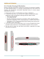
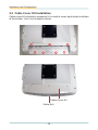
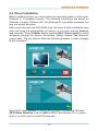
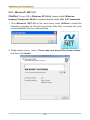
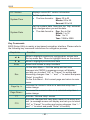
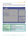
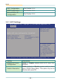
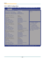
1
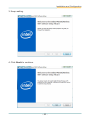
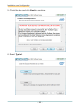
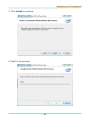
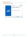
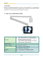
M1920
19" Fanless Intel® Medical Station
User's Manual
Version 1.1
P/N: 4012192000110P
2013.12
-1-
This page is intentionally left blank.
Revision History
Version
Release Time
Description
1.0
November 2012
Initial release
1.1
December 2013
Add Windows 8.X Driver support
Revise Driver Installation illustration
in
1.4 Specifications P.4
2.1 Getting Started P.10
2.4 Driver Installation P.17 P.25
-i-
Contents
Revision History.............................................................i
Preface........................................................................vi
Copyright Notice..................................................................vi
Declaration of Conformity...................................................vi
About This User's Manual.................................................viii
Technical Support..............................................................viii
Important Safety Instructions.............................................ix
Classification.........................................................................x
Disposing of Your Old Product............................................x
Symbols Description............................................................xi
Warranty...............................................................................xii
Chapter 1 General Introduction......................................1
1.1 Introduction....................................................................2
1.2 Packing List....................................................................2
1.3 Ordering Information.....................................................3
1.4 Specifications.................................................................4
1.5 Overview.........................................................................7
1.6 Dimensions.....................................................................8
Chapter 2 Installation and Configuration.........................9
2.1 Getting Started.............................................................10
2.1.1 Locating Controls and Connecting Ports.................. 11
2.1.2 Periodic Cleaning & Disinfection................................ 14
2.2 Cable Cover Kit Installation.........................................16
2.4 Driver Installation.........................................................17
2.4.1
2.4.2
2.4.3
2.4.4
2.4.5
2.4.6
2.4.7
2.4.8
2.4.9
Microsoft .NET 4.0........................................................ 18
DirectX 9.0c................................................................... 20
Camera Codec.............................................................. 22
Chipset Driver Installation........................................... 25
Management Engine Installation................................. 28
Audio Driver Installation.............................................. 31
Graphics Driver Installation......................................... 35
LAN Driver Installation................................................. 38
WiFi Driver Installation................................................. 42
- ii -
Contents
2.4.10
2.4.11
2.4.12
2.4.13
2.4.14
Bluetooth Driver Installation..................................... 47
RFID Driver Installation (optional)............................. 51
Function Keys Installation......................................... 53
Smart Card Reader Driver Installation...................... 56
Touch Screen Driver Installation............................... 58
2.5 How to use ...................................................................60
2.5.1
2.5.2
2.5.3
2.5.4
2.5.5
Function Keys............................................................... 60
Touch Screen Calibration............................................ 64
PenMount Gesture........................................................ 69
Bluetooth....................................................................... 73
Smart Card Reader....................................................... 74
3.2.1
3.2.2
3.2.3
3.2.4
3.2.5
3.2.6
ACPI Settings................................................................ 82
CPU Configuration....................................................... 83
SATA Configuration...................................................... 84
AMT Configuration....................................................... 87
USB Configuration....................................................... 88
F81216 Secondary Super IO Configuration............... 89
Chapter 3 BIOS...........................................................78
3.1 BIOS Main Setup..........................................................79
3.2 Advanced Settings.......................................................81
3.3 Chipset Settings...........................................................91
3.3.1 System Agent (SA) Configuration............................... 92
3.3.2 PCH-IO Configuration.................................................. 96
3.4 Boot Settings..............................................................101
3.5 Security.......................................................................102
3.6 Save & Exit Options...................................................104
Appendix..................................................................105
1. Arm Kit............................................................................106
1.1 Wall-mount ARM (ARM-1552M).................................... 106
1.2 Wall-mount ARM w/ Power Box (ARM-1682M)............ 107
1.3 Ceiling-mount ARM (ARM-1752M)................................ 108
2. RF Keyboard.................................................................. 110
2.1 Specifications................................................................ 110
2.2 Overview......................................................................... 110
2.3 Function Key.................................................................. 111
- iii -
Contents
3. Medical Arm Mounting.................................................. 113
4. How to use RFID............................................................ 114
5. How to use Camera....................................................... 117
- iv -
This page is intentionally left blank.
-v-
Preface
Copyright Notice
All Rights Reserved.
The information in this document is subject to change without prior notice in
order to improve the reliability, design and function. It does not represent a
commitment on the part of the manufacturer.
Under no circumstances will the manufacturer be liable for any direct, indirect,
special, incidental, or consequential damages arising from the use or inability
to use the product or documentation, even if advised of the possibility of such
damages.
This document contains proprietary information protected by copyright. All rights
are reserved. No part of this manual may be reproduced by any mechanical,
electronic, or other means in any form without prior written permission of the
manufacturer.
Declaration of Conformity
CE
The CE symbol on your product indicates that it is in compliance with the
directives of the Union European (EU). A Certificate of Compliance is
available by contacting Technical Support.
This product has passed the CE test for environmental specifications when
shielded cables are used for external wiring. We recommend the use of shielded
cables. This kind of cable is available from ARBOR. Please contact your local
supplier for ordering information.
FCC Class B
This device complies with Part 18 of the FCC Rules. Operation is subject to
the following two conditions:
(1)This device may not cause harmful interference, and
(2)This device must accept any interference received, including interference
that may cause undesired operation.
NOTE:
This equipment has been tested and found to comply with the limits for a
Class B digital device, pursuant to Part 18 of the FCC Rules. These limits
are designed to provide reasonable protection against harmful interference
in a residential installation. This equipment generates, uses and can radiate
radio frequency energy and, if not installed and used in accordance with
the instructions, may cause harmful interference to radio communications.
However, there is no guarantee that interference will not occur in a particular
installation. If this equipment does cause harmful interference to radio or
television reception, which can be determined by turning the equipment off and
- vi -
Preface
on, the user is encouraged to try to correct the interference by one or more of the
following measures:
-- Reorient or relocate the receiving antenna.
-- Increase the separation between the equipment and receiver.
-- Connect the equipment into an outlet on a circuit different from that to which
the receiver is connected.
-- Consult the dealer or an experienced radio/TV technician for help.
IEC 60601-1/EN60601-1/EN60601-1-2
This product complies with the system standard IEC 60601-1 Medical Electrical
Equipment Part 1: General Requirements for Safety. And therefore, the product
is exclusively interconnected with IEC 60601-1 certified equipment in the patient
environment.
Equipment connected to the analog or digital interfaces of the unit must comply
with the respective IEC standards (e.g. IEC 60601-1 for medical equipment).
Furthermore all configurations shall comply with the current version of the
standard for SYSTEMS IEC 60601-1-1. Everybody who connects additional
equipment to the signal input part or signal output part configures a medical
system, and is therefore responsible that the system complies with current
version of the requirements of the system standard IEC 60601-1-1. If in doubt,
consult the technical service department or your local representative.
RoHS
ARBOR Technology Corp. certifies that all components in its products are
in compliance and conform to the European Union’s Restriction of Use of
Hazardous Substances in Electrical and Electronic Equipment (RoHS) Directive
2002/95/EC.
The above mentioned directive was published on 2/13/2003. The main purpose
of the directive is to prohibit the use of lead, mercury, cadmium, hexavalent
chromium, polybrominated biphenyls (PBB), and polybrominated diphenyl
ethers (PBDE) in electrical and electronic products. Member states of the EU
are to enforce by 7/1/2006.
ARBOR Technology Corp. hereby states that the listed products do not
contain unintentional additions of lead, mercury, hex chrome, PBB or PBDB that
exceed a maximum concentration value of 0.1% by weight or for cadmium
exceed 0.01% by weight, per homogenous material. Homogenous material
is defined as a substance or mixture of substances with uniform composition
(such as solders, resins, plating, etc.). Lead-free solder is used for all terminations
(Sn(96-96.5%), Ag(3.0-3.5%) and Cu(0.5%)).
- vii -
Preface
SVHC / REACH
To minimize the environmental impact and take more responsibility to the earth
we live, Arbor hereby confirms all products comply with the restriction of SVHC
(Substances of Very High Concern) in (EC) 1907/2006 (REACH --Registration,
Evaluation, Authorization, and Restriction of Chemicals) regulated by the European Union. All substances listed in SVHC < 0.1 % by weight (1000 ppm).
About This User's Manual
This user's manual provides general information and installation instructions
about the product. This User’s Manual is intended for experienced users and
integrators with hardware knowledge of personal computers. If you are not
sure about any description in this booklet. Please consult your vendor before
further handling.
Technical Support
All ARBOR products are built to the most accurate specifications to ensure
reliable performance in the harsh and demanding conditions typical of
industrial environments. Whether your new equipment is destined for the
laboratory or the factory floor, you can be assured that your product will
provide the reliability and ease of operation. Your satisfaction is our primary
concern. We want you to get the maximum performance from your products.
So if you run into technical difficulties, we are here to help. For the most
frequently asked questions, you can easily find answers in your product
documentation. These answers are normally a lot more detailed than the ones
we can give over the phone. So please consult this manual first. If you still
cannot find the answer, gather all the information or questions that apply to
your problem, and with the product close at hand, call your dealer. Our dealers
are well trained and ready to give you the support you need to get the most
from your products. In fact, most problems reported are minor and are able
to be easily solved over the phone. We are always ready to give advice on
application requirements or specific information on the installation and
operation of any of our products. Please do not hesitate to call or e-mail us at:
http://www.arbor.com.tw
E-mail: [email protected]
Contact Information
Add: 10F., No.700, Zhongzheng Rd., Zhonghe Dist., New Taipei City
235, Taiwan
TEL: 886-2-8226-9396
- viii -
Preface
Important Safety Instructions
Read these safety instructions carefully:
1. Read all cautions and warnings on the equipment.
2. Place this equipment on a reliable surface when installing. Dropping it or
letting it fall may cause damage
3. Make sure the correct voltage is connected to the equipment.
4. For pluggable equipment, the socket outlet should be near the equipment
and should be easily accessible.
5. Keep this equipment away from humidity.
6. Disconnect this equipment from the A/C outlet before cleaning it. Use a
moist cloth. Do not use liquid or sprayed detergent for cleaning.
7. To fully disengage the power to the unit, please disconnect the power from
the AC outlet.
8. Do not scratch or rub the screen with a hard object.
9. Never use any of the solvents, such as Thinner Spray-type cleaner, Wax,
Benzene, Abrasive cleaner, Acid or Alkaline solvent, on the Medical Display.
Harsh chemicals may cause damage to the cabinet and the touch sensor.
10. Remove dirt with a lightly moistened cloth and a mild solvent detergent.
Then wipe the cabinet with a soft dry cloth.
11. The openings on the enclosure are for air convection and protect the
equipment from overheating. DO NOT COVER THE OPENINGS.
12. Position the power cord so that people cannot step on it. Do not place
anything over the power cord.
13. If the equipment will not be used for a long time, disconnect it from the
power source to avoid damage by transient overvoltage.
14. Never pour any liquid into openings. This may cause fire or electrical
shock.
15. Never open the equipment. For safety reasons, the equipment should be
opened only by qualified service personnel.
16. If one of the following situations arises, get the equipment checked by
service personnel:
a. The power cord or plug is damaged.
b. Liquid has penetrated into the equipment.
c. The equipment has been exposed to moisture.
d. The equipment does not work well, or you cannot get it to work according
to the user’s manual.
e. The equipment has been dropped or damaged.
f. The equipment has obvious signs of breakage.
17. The sound pressure level at the operator’s position, according to IEC
- ix -
Preface
704-1:1982, is no more than 70dB(A).
18. Keep this User’s Manual for later reference.
19. DO NOT LEAVE THIS EQUIPMENT IN AN UNCONTROLLED
ENVIRONMENT WHERE THE STORAGE TEMPERATURE IS BELOW
-20° C (-4° F) OR ABOVE 60° C (140° F). THIS MAY DAMAGE THE
EQUIPMENT.
UL Class II Classification: With respect to electric shock, fire
and mechanical hazards only, in accordance with UL-60601-1
and CAN/CSA C22.2 No. 601.1.
E322565
Classification
• Powered by Class II power supply
• No applied part
• Degree of protection against the ingress of water: IPX0
• Mode of operation: Continuous
• The equipment is not suitable for use in the presence of a flammable
anesthetic mixture with air or nitrous oxide: Not AP or APG Category.
Disposing of Your Old Product
• Within the European Union
EU-wide legislation, as implemented in each Member State,
requires that waste electrical and electronic products carrying the
mark (left) must be disposed of separately from normal household
waste.
This includes monitors and electrical accessories, such as signal cables or
power cords. When you need to dispose of your display products, please
follow the guidance of your local authority, or ask the shop where you
purchased the product, or if applicable, follow any agreements made between
yourself. The mark on electrical and electronic products only applies to the
current European Union Member States.
• Outside the European Union
If you wish to dispose of used electrical and electronic products outside the
European Union, please contact your local authority so as to comply with the
correct disposal method.
-x-
Preface
Symbols Description
This symbol of “CAUTION” indicates that there is a danger of
injury to the user or a risk of damage to the product, should
warning notices be disregarded.
Battery Recycle
E322565
37GC
UL Classified Certification
Compliant with ISO 13485
MEDICAL DEVICES
Safety Requirements for Medical Electrical System
UL/EN-60601
CANCSA C22.2
NO. 601.1
Power on/off
UL Class II safety symbol
Indoor Use Only
This symbol indicates electrical warning.
Change of electric current:
Internal: positive current
External: negative current
Refer to the operating instructions.
- xi -
Preface
Activate the menu
MENU
MENU
Activate the phone
Volume up/down
Brightness up/down
MENU
Warranty
This product is warranted to be in good working order for a period of one year
from the date of purchase. Should this product fail to be in good working order
at any time during this period, we will, at our option, replace or repair it at no
additional charge except as set forth in the following terms. This warranty
does not apply to products damaged by misuse, modifications, accident or
disaster.
Vendor assumes no liability for any damages, lost profits, lost savings or any
other incidental or consequential damage resulting from the use, misuse of,
or inability to use this product. Vendor will not be liable for any claim made by
any other related party.
Vendors disclaim all other warranties, either expressed or implied, including but
not limited to implied warranties of merchantability and fitness for a particular
purpose, with respect to the hardware, the accompanying product’s manual(s)
and written materials, and any accompanying hardware. This limited warranty
gives you specific legal rights.
Return authorization must be obtained from the vendor before returned
merchandise will be accepted. Authorization can be obtained by calling or
faxing the vendor and requesting a Return Merchandise Authorization (RMA)
number. Returned goods should always be accompanied by a clear problem
description.
- xii -
This page is intentionally left blank.
- xiii -
This page is intentionally left blank.
- xiv -
General Information
1
Chapter 1
General Information
Chapter 1 General Introduction
-1-
General Information
1.1 Introduction
The medical station, M1920, focuses on patient care application. With
built-in low power consumption Intel® Core™ i7-2610UE or Celeron® 827E
Processor, fanless and streamline design, which makes it suitable for using
in hospitals and clinics. Moreover, M1920, as the expert medical station, is a
terminal of excellent graphic computing to support quality image preocessing
for diagnosis, PACS, ultrasound and endoscopy. The 19" touch screen, selfdefined function key and abundant expansions make clinicians and patients
operate more conveniently. Regarding mobile communication, the M1920
can connect to WLAN, which gives it accessibility for eHealthcare medical
care. Other integrated vertical application functions include 5.0 Megapixel
Camera, RFID Reader, SD/SDHC slot, Dual-slot Smart Card Reader and
optional Slim DVD-RW.
•
•
•
•
•
•
•
•
•
•
•
Fanless Design
Applicable for Clinical Station, Vital Sign, PACS
Soldered Onboard Intel® Core™ i7-2610UE or Celeron® 827E Processor
19 inch LCD with Resistive Touch
EN60601-1, EN60601-1-2, UL60601-1 Certified
Streamline Appearance - 59mm in Thickness
Multi-connectivity (Bluetooth, WLAN)
RFID Reader, 5.0 Megapixel Camera, Smartcard Reader, RF Keyboard
and Slim DVD-RW
Isolated Serial Ports, USB and LAN Ports
Multi-expansion (3 x RS-232, 4 x USB, 2 x LAN, 1 x Displayport and 1 x
SD Card)
Intel® SSD Compatible
1.2 Packing List
1 x M1920
Accessory Package:
1 x User’s Manual
1 x Driver DVD
-2-
General Information
1 x Power Cord (Left, French standard cordset)
1 x Power Cord (Right, American standard
cordset)
1 x 90W Power Adapter
Before up and running, please make sure the package contains all of above accessories. If any of the above items is damaged or missing, contact your vendor
immediately.
1.3 Ordering Information
M1920-2610UE
19” Fanless Intel® Core™ i7-2610UE Medical Station
with WiFi and Bluetooth
M1920-827E
19” Fanless Intel® Celeron® 827E Medical Station with
WiFi and Bluetooth
The following items are normally optional, but some vendors may include
them as a standard package, or some vendors may not carry all the items.
Optional Accessories
ARM Kit
Hospital Arm (refer to Appendix)
Optional Configuration (Configure to Order Service) (Not Sold Separately)
*RFKB-185x
RF Keyboard remoter (refer to Appendix) and module
RFID-1920
RFID module kit
*To activate RF keyboard, you must long-press “pairing key” the first time you
use it in the process of booting up for pairing keyboard and computer.
-3-
General Information
CAM-1920
5.0MP CMOS camera module kit
DVDRW-1920
Slim DVD-RW Drive module kit
HDD-1920
2.5” 320GB SATAII HDD kit
80GB SSD
Intel® 2.5” 80GB SATAIII SSD kit
1.4 Specifications
System
CPU
Intel® Core™ i7-2610UE 1.5 GHz processor
Intel® Celeron® 827E 1.4 GHz processor
Graphics Controller
Intel® HD Graphics 3000 for i7-2610UE
Intel® HD Graphics for 827E
Memory
4GB DDR3 SO-DIMM memory module installed
Chipset
Intel® QM67 for i7-2610UE; Intel® HM65 for
827E
Storage
32GB mSATA SSD; 2.5” 320GB SATA HDD
(optional); Intel® 40GB SSD (optional)
OS Support
Windows 8 Embedded / Windows 8 Professional
Windows Embedded 7 / Windows 7 Professional
Windows XP Embedded / Windows XP
Professional
Ubuntu and Fedora Linux compliant
Peripherals & Devices
Camera
1 x 5.0 megapixel CMOS camera with autofocus (optional)
-4-
General Information
RFID
13.56MHz RFID reader with ISO 14443A/
14443B/15693 support (optional)
WLAN
1 x Intel® Centrino® Advanced-N 6205 802.11
a/b/g/n Mini PCIe Wireless LAN card installed
Bluetooth
1 x Bluetooth 2.1 + EDR
RF Keyboard
1 x RF Keyboard (optional)
DVD-RW
1 x Slim DVD-RW (optional)
Docking Bay
For the alternative of External Battery or PCIe
x16 Expansion box (optional)
SD Card
1 x SD/SDHC slot
Smart Card Reader
Dual slots Smart Card Readers
I/O interface
Audio I/O
1 x Integrated microphone, 2 x Integrated 3W
speakers, 1 x Mic-in, 1 x Line-out
Video output
1 x DisplayPort
Video input
1 x SDI connector (optional)
LAN
2 x RJ45 connectors for GbE LAN with 4KV
isolation
Serial Port
2 x RS-232 port with 4KV isolation, 1 x RS232/422/485 with 4KV isolation
USB Port
4 x USB 2.0 ports
1 x USB 2.0 port with 4KV isolation (on the top)
Button & Indicator
Function Key
1 x Menu button
1 x Touch and LCD on/off button
1 x Brightness up button
1 x Brightness down buton
1 x Voice up button
1 x Voice down button
1 x Programmable button
1 x Power on/off button
LCD Display
Size/Type
19" TFT Active Matrix Panel
Max. Resolution
1280 x 1024 (SXGA) with 16.2M colors
Luminance
350 cd/m² (typ.)
-5-
General Information
Contrast Ratio
1000:1 (typ.)
Viewing Angle
+85° ~ -85° (H), +80° ~ -80°(V)
Backlight Type
LED
Touch Screen
Type
5 wire Analog Resistive Touch
Controller Interface
USB interface
Mechanical & Environmental
Operating Temp.
0 ~ 40ºC (32 ~ 104ºF)
Storage &
Transportation Temp.
-20 ~ 60ºC (-4 ~ 140ºF)
Humidity
10 ~ 95% RH @ 40ºC, non-condensing
Dimensions (W x D x H) 399.4 x 459.5 x 59 mm (15.72" x 18.09" x 2.32")
Gross Weight
7.5 Kg (16.53 lb)
Regulatory
CE, FCC Class B, EN60601-1, EN60601-1-2,
UL60601-1 certified
Vibration
5 ~ 500Hz, 1G random operation (SSD only)
Shock
10G peak (11m/sec)
Operational Altitude
below 2000m
Power Requirement
Adapter Input
100 ~ 240 VAC (Full Range)
Adapter Output
DC 18V, 5A, 90W with medical certificate
-6-
General Information
1.5 Overview
-7-
General Information
1.6 Dimensions
Unit: mm
-8-
Installation and Configuration
2
Chapter 2
Installation and
Configuration
Chapter 2 Installation and Configuration
-9-
Installation and Configuration
2.1 Getting Started
This chapter is intended to give users the information about how to utilize a
variety of M1920’s functions. To get familiar with the medical PC, take a few
minutes to read this chapter.
Before installing the operating system and driver utilities, you should prepare
your own USB keyboard, USB mouse, USB DVD-ROM drive, and the power
adapter included in the accessory box. When the operating system on your
computer is ready, use accompanying Driver DVD to install drivers and utilities
for respective devices. M1920 supports Win7, Win XP and Window 8.X. The
following sections will guide you through drivers and utilities installation step
by step.
Before installing the drivers (and utilities), prepare the following:
1. a USB keyboard
2. a USB DVD-ROM drive
3. a USB Mouse
- 10 -
Installation and Configuration
2.1.1 Locating Controls and Connecting Ports
Refer to below illustration for locations of I/O ports, function buttons and the
external battery.
Front View
5.0 Megapixel Camera (optional)
Dual Smart
Card Reader
Slots
Microphone
RFID (optional)
Power On/Off
Menu
Brightness Up/Down
Programmable Button
Volume Up/Down
Screen On/Off
Function Keys (default) Description:
Programmable Button: set self-defined function
Volume Up/Down: adjusts the volume up or down
Brightness Up/Down: adjust the brightness of the screen up or down
Menu: access to the Menu
Power On/Off: the power button to turn on/off the PC (must hold the
button for about 2 seconds)
Screen On/Off: used to turn on/off screen but the system itself is not
influenced
- 11 -
Installation and Configuration
Rear Side
The rear side contains one power jack, one LAN port and one USB port.
3W Speaker
3W Speaker
PCIe x16 Expansion Slot (optional)
/ External Battery
(optional)
Warning:
The aluminum plate on the rear panel is highly heated when the medical PC
is operating. DO NOT touch it during operating.
*The temperature will reach up to 60°C.
Bottom Side
Mic-in Line-out
RS-232 Ports
SDI Connector
LAN RS-232/422/485 Port
USB
(optional)
Displayport
DC-IN Power Jack
- 12 -
Installation and Configuration
Top Side
USB
Left Side
Right Side
Slim DVD-RW
(optional)
Dual Smart Card
Reader Slots
SD/SDHC Slot
- 13 -
Installation and Configuration
2.1.2 Periodic Cleaning & Disinfection
M1920 is generally employed in medical environment, for example, hospitals,
as expert medical station. It is strongly recommended that users follow the
cleaning and disinfection instructions described below to ensure proper
maintenance activities.
1. Always power off your unit first when you clean or disinfect it.
2. To wipe the outer case, use lint-free cloth, lightly moistened with warm
water and a mild, non-abrasive cleaning solution made of either:
• 70% isopropyl alcohol
• 10% bleach solution
• Dimethyl ethylbenzyl ammonium chlorides 0.125%, dimethyl benzyl
ammonium chlorides 0.125%, Isopropyl alcohol 14.850% (Sani-Cloth®)
• Isopropanol 17.2%; Diisobutylphenoxyethyl dimethyl bezyl ammonium
chlorides 0.28% (CaviCide®)
3. The touch screen can be wiped down (e.g. to remove fingerprints) during
operation while powered on using standard computer screen solution.
4. Use dry cloth to clean the rear panel and bottom, especially the areas
around the connectors.
- 14 -
Installation and Configuration
Caution:
•
•
•
•
•
•
•
•
•
Do not spill liquids on or around the medical PC.
Do not use other solutions than the ones mentioned above.
Do not touch, press or rub the display panel with abrasive cleaning
compounds, instruments, brushes, or rough-surface materials.
Never spray cleaning liquids or foam onto the medical PC or soak it for
cleaning.
Do not use solvents to clean the unit.
Do not clean, disinfect, or sterilize any part of the system by autoclaving or
with the use of ethylene oxide gas; doing so may damage the unit.
Never spray or squirt any type of liquid onto the medical PC; if a spray, gel
or foam is needed, spray the liquid onto a cloth and then use the cloth to
wipe or rub down the component.
Always avoid contamination to minimize the need for disinfectants.
Do not spill, spray, or squirt liquids to the power block and the power
cable.
- 15 -
Installation and Configuration
2.2 Cable Cover Kit Installation
Cable cover kit included in accessory kit is used to cover input/output interface
at the bottom, lock it as illustration below.
Cable Cover Kit
Cable Exit
- 16 -
Installation and Configuration
2.4 Driver Installation
Before installing drivers, you must make sure operating system (in this case,
Windows 7) is installed correctly. The following instructions are based on
Windows 7 system. Different OS, like Windows XP, may differ somewhat, but
they are almost the same.
After you put the disk into DVD-ROM drive, the driver & utility installation main
menu will jump out automatically as follows, or you may execute autorun.
exe manually. Select Utilities before entering Win7 Driver Install to install
necessary program for drivers. Remember, always choose Yes whenever
system asks, “Do you want to allow the following program to make changes
to this computer?”
Note: AHCI under Utilities is used in the process of reinstalling OS while
SATA Mode Selection is set as AHCI in BIOS (See Section 3.2.3). Ignore
them if you don’t want to install OS manually.
- 17 -
Installation and Configuration
2.4.1 Microsoft .NET 4.0
Caution: If your OS is Windows XP 64 bit, please install Windows
Imaging Component 64-bit in advance before install .Net 4.0 Framework.
1. Click Microsoft .NET 4.0 on the main menu under Utilities to install the
necessary program for function keys driver. After that, a window will jump
out immediately. Wait for extracting files.
2. Read license terms, check “I have read and accept the license terms.”
and then click Install.
- 18 -
Installation and Configuration
3. Wait for installation progress.
4. Click Finish to close the window.
- 19 -
Installation and Configuration
2.4.2 DirectX 9.0c
1. Click DirectX 9.0c on the main menu under Utilities to install the necessary
program for function VGA & chipset. After that, a window will jump out
immediately. Choose “I accept the agreement” and click Next>.
2. Read the information, and click Next>.
- 20 -
Installation and Configuration
3. Wait for a while.
4. Click Finish to close the window.
- 21 -
Installation and Configuration
2.4.3 Camera Codec
1. Click Camera Codec on the main menu under Utilities to install the
necessary program for ccd. After that, a window will jump out immediately.
Wait for seconds.
2. Read the information, and click Next>.
- 22 -
Installation and Configuration
3. Choose destination folder and click Next>.
4. Wait for a while.
- 23 -
Installation and Configuration
5. Click Finish to close the window.
- 24 -
Installation and Configuration
2.4.4 Chipset Driver Installation
Now, back to upper level and select Win7 Driver Install. Still, always choose
Yes whenever system asks, “Do you want to allow the following program to
make changes to this computer?” Click Chipset.
- 25 -
Installation and Configuration
1. Click Next> to continue.
2. Read License Agreement and click Yes to continue.
- 26 -
Installation and Configuration
3. Read Readme File Information and click Next> to continue.
4. Click Finish to close the window.
Tips:
After chipset driver is installed, USB2.0 can be correctly recognized and SDHC/
SD card slot is activated, too. However, when SDHC/SD card is removed from
its slot, you have to reboot the system to reuse the device again.
- 27 -
Installation and Configuration
2.4.5 Management Engine Installation
1. Click Management Engine of the main menu to install the driver for chipset,
too. Wait for the process.
2. Check the little box and click Next> to continue.
- 28 -
Installation and Configuration
3. Read License Agreement and click Yes to continue.
4. Check the little box and click Install.
- 29 -
Installation and Configuration
5. Click Next> to continue.
6. Choose Yes to reboot computer.
- 30 -
Installation and Configuration
2.4.6 Audio Driver Installation
1. Click Audio of the main menu to install the audio device’s driver. Please
wait for a short while to initiate the installation.
2. Wait.
- 31 -
Installation and Configuration
3. Click Next to continue.
4. Click Next to continue.
- 32 -
Installation and Configuration
5. Wait for the process.
6. After installing the audio device driver, you will be asked if you would like
to restart the computer. It is required to select “Yes, I want to restart
my computer now.” in order to make sure the program will run properly.
Then, click Finish to proceed.
- 33 -
Installation and Configuration
Tips:
While using the medical PC to record, make sure Listen to this device this
option is not checked to avoid echo in recording file.
- 34 -
Installation and Configuration
2.4.7 Graphics Driver Installation
1. Click Graphic (32bit) (for Win7-32bit or 64bit for 64bit) of the main menu
to install the device driver. Check the box and then click Next to continue.
2. Please read the license agreement and click Yes to continue.
- 35 -
Installation and Configuration
3. Please read the Readme File for system requirements and installation
information, and click Next> to continue.
4. Wait for the process.
- 36 -
Installation and Configuration
5. Click Next> to continue.
6. After installing the graphics device’s driver, click Finish with Yes radio
button selected to restart your computer to have the changes take effect, or
with No to restart this computer later.
- 37 -
Installation and Configuration
2.4.8 LAN Driver Installation
1. Click LAN (32bit) (for Win7-32bit or 64bit for 64bit) of the main menu to
install LAN device’s driver. Wait for extracting.
2. Click Next> to continue.
- 38 -
Installation and Configuration
3. Accept the terms and click Next> to continue.
4. Click Next> to continue.
- 39 -
Installation and Configuration
5. Click Install.
6. Wait for the process.
- 40 -
Installation and Configuration
7. Click Finish to close the window.
- 41 -
Installation and Configuration
2.4.9 WiFi Driver Installation
1. Click WiFi (32bit) (for Win7-32bit or 64bit for 64bit) of the main menu to
install the driver for WiFi. Click Next> to continue.
2. Wait for the process.
- 42 -
Installation and Configuration
3. Keep waiting.
4. Click Next> to continue.
- 43 -
Installation and Configuration
5. Check the box and click Next> to continue.
6. Select Typical.
- 44 -
Installation and Configuration
7. Click Install to continue.
8. Wait for the process.
- 45 -
Installation and Configuration
9. Click Finish to close the window.
- 46 -
Installation and Configuration
2.4.10 Bluetooth Driver Installation
1. Click Bluetooth of the main menu to install the driver for WiFi. Set language.
2. Wait for the process.
3. Click Next> to continue.
- 47 -
Installation and Configuration
4. Please read the license agreement first; select I accept the terms in the
license agreement and then click Next> to continue.
5. Click Next> to install to this folder, or click Change to install to a different
folder.
- 48 -
Installation and Configuration
6. Click Install to start installation, or click Back to go back to the previous
step.
7. Wait for the process.
- 49 -
Installation and Configuration
8. Click Finish to complete installation.
9. Decide whether you want to reboot right now.
- 50 -
Installation and Configuration
2.4.11 RFID Driver Installation (optional)
1. Click RFID of the main menu to install the driver for RFID. Read the
information and then click Next> to continue.
2. Click Next> to install in this folder, or click Browse to install in a different
folder.
- 51 -
Installation and Configuration
3. The application is being installed, please wait for a while.
4. Click Finish to complete the installation.
- 52 -
Installation and Configuration
2.4.12 Function Keys Installation
1. Click Function Keys of the main menu to install the function key utility.
Select components to install and click Next>.
2. Set destination folder and click Next>.
- 53 -
Installation and Configuration
3. Click Install to continue.
4. Wait for the process.
- 54 -
Installation and Configuration
5. Click Close to finish installation.
- 55 -
Installation and Configuration
2.4.13 Smart Card Reader Driver Installation
1. Click Smart Card of the main menu to install the driver for smart card. Wait
for the process.
2. Click Next> to continue.
- 56 -
Installation and Configuration
3. Wait for the process.
4. Click Finish to close the window.
- 57 -
Installation and Configuration
2.4.14 Touch Screen Driver Installation
1. Click Touch Screen of the main menu to install the driver for touch screen.
Click Next to continue.
2. Read License Agreement and click I Accept to continue.
- 58 -
Installation and Configuration
3. Set destination and click Install.
4. Wait for the process.
- 59 -
Installation and Configuration
5. Choose reboot and click Finish.
2.5 How to use
Once you have installed all drivers, you have right to use few useful applications. The following sections provide a brief instruction of how to use them..
2.5.1 Function Keys
1. Press Menu button on front panel (refer to Section 2.1.1 for its position)
to activate the program, or activate it from All Programs. Click
ArborTabletui.
- 60 -
Installation and Configuration
2. An icon will appear in system tray immediately. Right-click the icon and
select Show to call function key’s program. Each symbol’s function is listed
below:
7
1
2
5
6
- 61 -
3
4
Installation and Configuration
1
volume down
2
volume up
3
brightness down
4
brightness up
5
self-define program or function
6
restore defaults
7
close the window
3. To be more precise, pressing Program on previous illustration allows you
to change function key’s default setting or designate specific program for P
button on front panel. You may also choose Set Function Keys to display
the same window as below.
Correspond
to the P
button on
front panel.
- 62 -
Installation and Configuration
4. Click inverted triangle to extend drop-down menu and choose new function.
5. Alternatively, click Program to set Function Keys as any program’s hot key.
- 63 -
Installation and Configuration
2.5.2 Touch Screen Calibration
1. After installing the touch screen driver, a set of shortcuts will be generated
in All Programs. Please click PenMount Control Panel.
2. The program consists of 3 tabs. The left one is Device, in it, you can find
how many devices are detected in your system. Select one device icon and
tap Configure, or double tap the device icon for touch screen calibration.
- 64 -
Installation and Configuration
3. And then another window with Calibrate tab will jump out.
Device Calibration Dialog
A. The Calibrate Tab
This function offers two ways to calibrate your touch screen. ‘Standard
Calibration’ adjusts most touch screens while ‘Advanced Calibration’
adjusts aging touch screens.
a. Standard Calibration
The Standard Calibration function lets you match the touch screen to your
display so that the point you touch is accurately tracked on screen. Standard
Calibration only requires four points for calibration and one point for confirmation. Under normal circumstance, Standard Calibration is all you need to
perform an accurate calibration.
1) Please tap the Standard Calibration button to start calibration procedures.
2) After that, the 1st crosshair will appear on white screen. Use your finger
or stylus to touch the red center and hold down until the screen shows the
message - “Lift off to proceed”.
3) The 2nd crosshair follows immediately. Do the process again. After the
fifth red point calibration is complete, the program will jump out automatically, or you may press ESC key to quit it during calibration process. Alternatively, doing nothing for a while equates to pressing ESC.
- 65 -
Installation and Configuration
1st crosshair
b. Advanced Calibration
The Advanced Calibration function improves the accuracy of calibration by
using more involved engineering calculations. Use this function only if you
have tried the Standard Calibration and there is still a discrepancy in the way
the touch screen maps to the display. You can choose 9, 16 or 25 points to
calibrate, though we suggest that you first try 9 points, if it is still not tracking well then try 16 or 25 points. The more points you use for calibration, the
greater the accuracy is. Errors in calibration may occur due to viewing angle,
or individual skill, and there may be little difference in using 16 or 25 points.
Note that a stylus is recommended for most accurate results.
Plot Calibration Data
Check this function to have touch panel linearity comparison graph appear
when you finish Advanced Calibration. The black lines reflect the ideal linearity assumed by PenMount’s application program while the blue lines show the
approximate linearity calculated by PenMount’s application program as the
result of user’s execution of Advance Calibration.
Turn off EEPROM storage
Tick this function to disable the write-in of calibration data in Controller.
Please tap the Advanced Calibration button to start calibration procedures
and do the rest as explained in Standard Calibration.
- 66 -
Installation and Configuration
Turn off
EEPROM
storage
Plot Calibration
Data
B. The Edge Compensation Tab
Under the same level where you calibrate your screen, you may find the tab.
This tab is the edge compensation settings for the advanced calibration. You
can adjust the settings from 0 to 30 for accommodating the difference of each
touch panel.
- 67 -
Installation and Configuration
3. Press OK to close former window and back to upper level. As mentioned
before, the program consists of 3 tabs and the central one is Tool, switch to
it and click Draw to test PenMount touch screen operation.
- 68 -
Installation and Configuration
2.5.3 PenMount Gesture
1. Now that this medical PC supports touchscreen function, you may take
advantage of that to set hotkey or do other settings. Single-click a small
icon like a monitor in system tray. If it's absent, you can recall it from All
Programs. The default setting is inactive, so you need to click Gesture
Setting to start the program.
- 69 -
Installation and Configuration
2. Check “Enable” and click the upward arrow in red square. You may also
disable gesture function by canceling “Enable” box.
3. And then another Gesture Select window will pop up. Each mark in this
menu represents your gesture on screen. For example, the upward arrow
indicates that you move your finger across the touch screen from bottom
to top. The rest are similar. You may use your gesture applied on the
touchscreen to do further configuration. Select a gesture you would like to
define.
- 70 -
Installation and Configuration
4. Then again, choose Hot Key, Action or Application to set each gesture’s
corresponding function. You may disable respective gesture, too. And
remember to press Apply after all.
- 71 -
Installation and Configuration
- 72 -
Installation and Configuration
2.5.4 Bluetooth
1. In addition to the above, the medical PC supports Bluetooth as well. Once
everything is installed, click the program icon named Bluetooth Places on
desktop to turn on its application.
2. Double-click the central golden ball to start/stop searching for surrounding
Bluetooth devices. Wait for seconds. If any device around this PC is
detected, its icon will appear around the central ball. Drag scrollbar to
show more Bluetooth devices. Click any detected item and upper icons to
execute further operation.
- 73 -
Installation and Configuration
2.5.5 Smart Card Reader
1. You may install your own Smart Card Reader application; however, our
driver DVD incorporates a program to test this device. Please execute
DEMO4.exe from the following path: disk drive\Smart Card Reader\Tool
2. Insert a smart card into upper reader (Refer to Section 2.1.1 Right Side).
Make sure the chip facing towards you.
- 74 -
Installation and Configuration
3. Click Select reader. A sub-window will jump out to ask which reader you
want to test. Select Reader 1. Reader 0 represents the upper reader. Click
OK to close the sub-window. Then, click Connect. If Reader 1 successfully
detects smart card, its information will be shown in box below.
- 75 -
Installation and Configuration
3. Press Set Format to set further video format.
4. Press Record Film or Take Picture icon to execute these works. Files are
saved under ccd folder in Documents.
- 76 -
This page is intentionally left blank.
- 77 -
BIOS
3
Chapter 3
BIOS
Chapter 3 BIOS
- 78 -
BIOS
3.1 BIOS Main Setup
The AMI BIOS provides a Setup utility program for specifying the system
configurations and settings. The BIOS RAM of the system stores the Setup
utility and configurations. When you turn on the computer, the AMI BIOS is
immediately activated. To enter the BIOS SETUP UTILITY, press “Delete”
once the power is turned on. When the computer is shut down, the battery on
the motherboard supplies the power for BIOS RAM.
The Main Setup screen lists the following information:
Aptio Setup Utility - Copyright (C) 2010 American Megatrends, Inc.
Main Advanced Chipset Boot Security Save & Exit
BIOS Information
BIOS Vendor
Core Version
Compliency
BIOS version
Build Date and Time
American Megatrends
4.6.4.0
UEFI 2.1
M1920 0.14
08/09/2012 19:09:36
EC Version
0.09
System Date
System Time
[Tue 09/25/2012]
[17:38:10]
Access Level
Administrator
Set the Date. Use Tab
to switch between
Date elements.
→←: Select Screen
↓↑: Select Item
Enter: Select
+/-: Change Opt.
F1: General Help
F2: Previous Values
F9: Optimized Defaults
F10: Save and Exit
ESC: Exit
Version 2.10.1208. Copyright (c) 2010 American Megatrendes, Inc.
Setting
Description
BIOS Information
BIOS Vendor
displays vendor name
Core Version
displays current core version information
Compliency
displays compliant format
BIOS Version
displays current BIOS version information
Build Date and Time
the date that the BIOS version was made/updated
- 79 -
BIOS
EC Version
displays current EC version information
Set the system time.
System Time
System Date
► ► The time format is: Hour: 00 to 23
Minute: 00 to 59
Second: 00 to 59
Set the system date. Note that the ‘Day’ automatically changes when you set the date.
► ► The date format is: Day: Sun to Sat
Month: 1 to 12
Date: 1 to 31
Year: 1998 to 2099
Key Commands
BIOS Setup Utility is mainly a key-based navigation interface. Please refer to
the following key command instructions for navigation process.
Keystroke
Function
◄ ►
Move to highlight a particular configuration screen from
the top menu bar / Move to highlight items on the screen
▼ ▲
Move to highlight previous/next item
Enter
Select and access a setup item/field
Esc
On the Main Menu – Quit the setup and not save
changes into CMOS (a message screen will display
and ask you to select “OK” or “Cancel” for exiting and
discarding changes. Use “←” and “→” to select and press
“Enter” to confirm)
On the Sub Menu – Exit current page and return to main
menu
Page Up / +
Increase the numeric value on a selected setup item /
make change
Page Down -
Decrease the numeric value on a selected setup item /
make change
F1
Activate “General Help” screen
F10
Save the changes that have been made in the setup and
exit. (a message screen will display and ask you to select
“OK” or “Cancel” for exiting and saving changes. Use “←”
and “→” to select and press “Enter” to confirm)
- 80 -
BIOS
3.2 Advanced Settings
The “Advanced” setting page provides you the options to configure the details
of your hardware, such as ACPI, CPU, SATA, AMT, USB and Secondary Super IO.
Aptio Setup Utility - Copyright (C) 2010 American Megatrends, Inc.
Advanced
Legacy OpROM Support
Launch PXE OpROM
Launch Storage OpROM
►
►
►
►
►
►
[Disabled]
[Enabled]
ACPI Settings
CPU Configuration
SATA Configuration
AMT Configuration
USB Configuration
F81216 Secondary Super IO Configuration
Enable or Disable Boot
Option for Legacy
Network Devices.
→←: Select Screen
↓↑: Select Item
Enter: Select
+/-: Change Opt.
F1: General Help
F2: Previous Values
F9: Optimized Defaults
F10: Save and Exit
ESC: Exit
Version 2.10.1208. Copyright (c) 2010 American Megatrendes, Inc.
Setting
Description
Launch PXE OpROM
Enable or Disable (default) boot option for legacy
network devices.
Launch Storage
OpROM
Enable (default) or Disable boot option for legacy
mass storage devices with Option ROM.
ACPI Settings
See Section 3.2.1
CPU Configuration
See Section 3.2.2
SATA Configuration
See Section 3.2.3
- 81 -
BIOS
AMT Configuration
See Section 3.2.4
USB Configuration
See Section 3.2.5
Second Super IO
Configuration
See Section 3.2.6
3.2.1 ACPI Settings
Aptio Setup Utility - Copyright (C) 2010 American Megatrends, Inc.
Advanced
ACPI Settings
Enables or Disables
BIOS ACPI Auto
Configuration.
Enable ACPI Auto Configuration [Disabled]
Enable Hibernation
ACPI Sleep State
Lock Legacy Resources
[Enabled]
[S3 (Suspend to RAM)]
[Disabled]
→←: Select Screen
↓↑: Select Item
Enter: Select
+/-: Change Opt.
F1: General Help
F2: Previous Values
F9: Optimized Defaults
F10: Save and Exit
ESC: Exit
Version 2.10.1208. Copyright (c) 2010 American Megatrendes, Inc.
Setting
Description
Enable ACPI Auto
Configuration
Enable or Disable (default) BIOS ACPI Auto Configuration.
Enable Hibernation
Enable (default) or Disable system ability to hibernation (OS/S4 Sleep State). This option may be not
effective with some OS.
- 82 -
BIOS
ACPI Sleep State
Select the highest ACPI sleep state the system will
enter when the SUSPEND button is pressed.
► ► Options: S1 (CPU Stop Clock), S3 (Suspend to
RAM) (default) and Suspend Disabled.
Lock Legacy Resources
Enable or Disable (default) Lock of Legacy Resources
3.2.2 CPU Configuration
Aptio Setup Utility - Copyright (C) 2010 American Megatrends, Inc.
Advanced
CPU Configuration
Intel(R) Core(TM) i7-2610UE CPU @ 1.50GHz
Processor Stepping
206a7
Microcode Revision
15
Max Processor Speed
1500 MHz
Min Processor Speed
800 MHz
Processor Speed
1500 MHz
Processor Cores
2
Intel HT Technology
Supported
EMT64
Supported
→←: Select Screen
↓↑: Select Item
Enter: Select
+/-: Change Opt.
F1: General Help
F2: Previous Values
F9: Optimized Defaults
F10: Save and Exit
ESC: Exit
Version 2.10.1208. Copyright (c) 2010 American Megatrendes, Inc.
- 83 -
BIOS
3.2.3 SATA Configuration
Aptio Setup Utility - Copyright (C) 2010 American Megatrends, Inc.
Advanced
[Enabled]
SATA Controller(s)
[AHCI]
SATA Mode Selection
[Enabled]
Aggressive LPM Support
► Software Feature Mask Configuration
Serial ATA Port 1
Software Preserve
Port 1
Hot Plug
External SATA
SATA Device Type
Spin Up Device
Serial ATA Port 2
Software Preserve
Port 2
Hot Plug
External SATA
SATA Device Type
Spin Up Device
Serial ATA Port 3
Software Preserve
Port 3
Hot Plug
External SATA
SATA Device Type
Spin Up Device
Serial ATA Port 4
Software Preserve
Port 4
Hot Plug
External SATA
SATA Device Type
Spin Up Device
Empty
Unknown
[Enabled]
[Disabled]
[Disabled]
[Hard Disk Driver]
[Disabled]
Empty
Unknown
[Enabled]
[Disabled]
[Disabled]
[Hard Disk Driver]
[Disabled]
UGBA24IA32HOT1 (32.3G
NOT SUPPORTED
[Enabled]
[Disabled]
[Disabled]
[Hard Disk Driver]
[Disabled]
Empty
Unknown
[Enabled]
[Disabled]
[Disabled]
[Hard Disk Driver]
[Disabled]
Enable or Disable SATA
Device.
→←: Select Screen
↓↑: Select Item
Enter: Select
+/-: Change Opt.
F1: General Help
F2: Previous Values
F9: Optimized Defaults
F10: Save and Exit
ESC: Exit
Version 2.10.1208. Copyright (c) 2010 American Megatrendes, Inc.
- 84 -
BIOS
Setting
Description
SATA Controller(s)
Enable (default) or Disable SATA device.
SATA Mode Selection
► ► Options: IDE and AHCI (default).
Aggressive LPM
Support
Enable (default) or Disable PCH to aggressively enter link power state.
Software Feature
Mask Configuration
See Software Feature Mask Configuration tab
Port 1-4
Enable (default) or Disable SATA Port
Hot Plug
Determines how SATA controller(s) operate.
Designates this port as Hot Pluggable.
► ► Options: Enabled and Disabled (default).
External SATA
Enable or Disable (default) external SATA support.
SATA Device Type
Identify the SATA port is connected to Solid State
Drive or Hard Dish Drive (default).
Spin Up Device
On an edge detect from 0 to 1, the PCH starts a
COMRESET initialization sequence to the device.
► ► Options: Enabled and Disabled (default).
- 85 -
BIOS
Software Feature Mask Configuration
Aptio Setup Utility - Copyright (C) 2010 American Megatrends, Inc.
Advanced
RAID0
RAID1
RAID10
RAID5
Intel Rapid Recovery Technology
OROM UI and BANNER
HDD Unlock
LED Locate
IRRT Only on eSATA
[Enabled]
[Enabled]
[Enabled]
[Enabled]
[Enabled]
[Enabled]
[Enabled]
[Enabled]
[Enabled]
Enable or disable
RAID0 feature.
→←: Select Screen
↓↑: Select Item
Enter: Select
+/-: Change Opt.
F1: General Help
F2: Previous Values
F9: Optimized Defaults
F10: Save and Exit
ESC: Exit
Version 2.10.1208. Copyright (c) 2010 American Megatrendes, Inc.
Setting
RAID0/1/10/5
Description
Enable (default) or Disable RAID0/1/10/5 feature.
Intel Rapid Recovery Enable (default) or Disable Intel Rapid Recovery
Technology
Technology.
OROM UI and BANNER
If enabled, then the OROM UI is shown. Otherwise,
no OROM banner or information will be displayed if
all disks and RAID volumes are Normal.
► ► Options: Enabled (default) and Disabled.
HDD Unlock
If enabled, indicates that the HDD password unlock
in the OS is enabled.
► ► Options: Enabled (default) and Disabled.
LED Locate
If enabled, indicates that the LED/SGPIO hardware
is attached and ping to locate feature is enabled on
the OS.
► ► Options: Enabled (default) and Disabled.
- 86 -
BIOS
If enabled, then only IRRT volumes can span internal
and eSATA drives. If disabled, then any RAID volume
IRRT Only on eSATA
can span internal and eSATA drives.
► ► Options: Enabled (default) and Disabled.
3.2.4 AMT Configuration
The tab displays Active Management Technology Parameters.
Aptio Setup Utility - Copyright (C) 2010 American Megatrends, Inc.
Advanced
Active Remote Assistance Process
[Disabled]
Trigger CIRA boot.
→←: Select Screen
↓↑: Select Item
Enter: Select
+/-: Change Opt.
F1: General Help
F2: Previous Values
F9: Optimized Defaults
F10: Save and Exit
ESC: Exit
Version 2.10.1208. Copyright (c) 2010 American Megatrendes, Inc.
Setting
Active Remote Assistance Process
Description
Trigger CIRA boot.
► ► Options: Enabled and Disabled (default).
- 87 -
BIOS
3.2.5 USB Configuration
Aptio Setup Utility - Copyright (C) 2010 American Megatrends, Inc.
Advanced
USB Configuration
USB Devices:
1 Drive, 1 Keyboard, 2 Mice, 6 Hubs
Legacy USB Support
EHCI Hand-off
USB Beep Switch
[Enabled]
[Disabled]
[Enabled]
Mass Storage Devices:
Generic STORAGE DEVICE 9454
[Auto]
Enables Legacy USB
support. AUTO option
disables legacy
support if no USB
devices are connected.
DISABLE option will
keep USB devices
available only for EFI
applications.
→←: Select Screen
↓↑: Select Item
Enter: Select
+/-: Change Opt.
F1: General Help
F2: Previous Values
F9: Optimized Defaults
F10: Save and Exit
ESC: Exit
Version 2.10.1208. Copyright (c) 2010 American Megatrendes, Inc.
Setting
Description
Enables (default) support for Legacy USB. AUTO
option disables legacy support if no USB devices are
Legacy USB Support
connected. DISABLE option will keep USB devices
available only for EFI applications.
EHCI Hand-off
This is a workaround for OSes without EHCI handoff support. The EHCI ownership change should be
claimed by EHCI driver.
► ► Options: Enabled and Disabled (default).
USB Beep Switch
Enable (default) or Disable USB Beep sound.
- 88 -
BIOS
Mass storage device emulation type. AUTO enumerates devices according to their media format. Optical
drives are emulated as CDROM, drives with no media will be emulated according to a drive type.
► ► Options: Auto (default), Floppy, Forced FDD,
Hard Disk, CD-ROM
Generic STORAGE
DEVICE 9454
3.2.6 F81216 Secondary Super IO Configuration
Aptio Setup Utility - Copyright (C) 2010 American Megatrends, Inc.
Advanced
F81216 Secondary Super IO Configuration
Super IO
► F81216
► F81216
► F81216
► F81216
Chip
Serial
Serial
Serial
Serial
Port
Port
Port
Port
0
1
2
3
Set Parameters of
Serial Port 0 (COMA)
Fintek F81216
Configuration
Configuration
Configuration
Configuration
→←: Select Screen
↓↑: Select Item
Enter: Select
+/-: Change Opt.
F1: General Help
F2: Previous Values
F9: Optimized Defaults
F10: Save and Exit
ESC: Exit
Version 2.10.1208. Copyright (c) 2010 American Megatrendes, Inc.
- 89 -
BIOS
Aptio Setup Utility - Copyright (C) 2010 American Megatrends, Inc.
Advanced
Enable or Disable
Serial Port (COM)
F81216 Serial Port 0 Configuration
Serial Port
Device Settings
[Enabled]
IO=2E0h; IRQ=4;
Change Settings
Device Mode
[IO=2E0h; IRQ=4;]
[Serial Port Functi...]
→←: Select Screen
↓↑: Select Item
Enter: Select
+/-: Change Opt.
F1: General Help
F2: Previous Values
F9: Optimized Defaults
F10: Save and Exit
ESC: Exit
Version 2.10.1208. Copyright (c) 2010 American Megatrendes, Inc.
Setting
Serial Port
Description
Enable (default) or Disable Serial Port (COM).
Select an optimal setting for Super IO device.
► ► Options: Auto
IO=2E0h; IRQ=4;
IO=2E0h; IRQ=3, 4, 5, 6, 7, 10, 11, 12;
IO=2F8h; IRQ=3, 4, 5, 6, 7, 10, 11, 12;
IO=3E8h; IRQ=3, 4, 5, 6, 7, 10, 11, 12;
IO=2E8h; IRQ=3, 4, 5, 6, 7, 10, 11, 12;
Change Settings
Change the Serial Port mode.
► ► Options:
Device Mode (only
for Serial Port 0)
Serial Port Function Mode
IR Mode, Pulse 1.6us, Full Duplex
IR Mode, Pulse 1.6us, Half Duplex
IR Mode, Pulse 3/16 Bit Time, Full Duplex
IR Mode, Pulse 3/16 Bit Time, Half Duplex
- 90 -
BIOS
3.3 Chipset Settings
Aptio Setup Utility - Copyright (C) 2010 American Megatrends, Inc.
Main Advanced Chipset Boot Security Save & Exit
System Agent (SA)
Parameters
► System Agent (SA) Configuration
► PCH-IO Configuration
→←: Select Screen
↓↑: Select Item
Enter: Select
+/-: Change Opt.
F1: General Help
F2: Previous Values
F9: Optimized Defaults
F10: Save and Exit
ESC: Exit
Version 2.10.1208. Copyright (c) 2010 American Megatrendes, Inc.
Setting
Description
System Agent (SA) Configuration
See Section 3.3.1
PCH-IO Configuration
See Section 3.3.2
- 91 -
BIOS
3.3.1 System Agent (SA) Configuration
Aptio Setup Utility - Copyright (C) 2010 American Megatrends, Inc.
Chipset
System Agent RC version
VT-d Capability
1.2.0.0
Supported
Config Graphics
Settings.
► Graphics Configuration
► Memory Configuration
→←: Select Screen
↓↑: Select Item
Enter: Select
+/-: Change Opt.
F1: General Help
F2: Previous Values
F9: Optimized Defaults
F10: Save and Exit
ESC: Exit
Version 2.10.1208. Copyright (c) 2010 American Megatrendes, Inc.
Setting
Description
Graphics Configuration
See Graphics Configuration tab
Memory Configuration
See Memory Configuration tab
- 92 -
BIOS
Graphics Configuration
Aptio Setup Utility - Copyright (C) 2010 American Megatrends, Inc.
Chipset
Graphics Configuration
IGFX VBIOS Version
IGfx Frequency
Primary Display
► LCD Control
2120
350 MHz
[Auto]
Select which of IGFX/
PEG/PCI Graphics
device should be
Primary Display Or
Select SG for
switchable Gfx.
→←: Select Screen
↓↑: Select Item
Enter: Select
+/-: Change Opt.
F1: General Help
F2: Previous Values
F9: Optimized Defaults
F10: Save and Exit
ESC: Exit
Version 2.10.1208. Copyright (c) 2010 American Megatrendes, Inc.
Setting
Description
Primary Display
Select which of IGFX/PEG/PCI Graphics device
should be Primary Display Or Select SG for switchable Gfx.
► ► Options: Auto (default), IGFX, PEG, PCI
LCD Control
See LCD Control tab
- 93 -
BIOS
LCD Control
Aptio Setup Utility - Copyright (C) 2010 American Megatrends, Inc.
Chipset
LCD Control
Primary IGFX Boot Display
[DP + LVDS]
Select the Video Device
which will be activated
during POST. This has no
effect if external
graphics present.
Secondary boot display
selection will appear
based on your selection.
VGA modes will be
supported only on
primary display
→←: Select Screen
↓↑: Select Item
Enter: Select
+/-: Change Opt.
F1: General Help
F2: Previous Values
F9: Optimized Defaults
F10: Save and Exit
ESC: Exit
Version 2.10.1208. Copyright (c) 2010 American Megatrendes, Inc.
Setting
Primary IGFX Boot
Display
Description
Select the Video Device which will be activated
during POST. This has no effect if external graphics
present. Secondary boot display selection will appear based on your selection. VGA modes will be
supported only on primary display.
► ► Options: VBIOS Default, CRT, Display Port,
LVDS, CRT + LVDS, DP + LVDS (default)
- 94 -
BIOS
Memory Configuration
Aptio Setup Utility - Copyright (C) 2010 American Megatrends, Inc.
Chipset
Memory Information
Memory RC Version
Memory Frequency
Total Memory
DIMM#0
DIMM#1
DIMM#2
DIMM#3
CAS Latency (tCL)
Minimum delay time
CAS to RAS (tRCDmin)
Row Precharge (tRPmin)
Active to Precharge (tRASmin)
1.2.0.0
1333 MHz
4096 MB (DDR3)
Not Present
Not Present
4096 MB (DDR3)
Not Present
9
9
9
24
→←: Select Screen
↓↑: Select Item
Enter: Select
+/-: Change Opt.
F1: General Help
F2: Previous Values
F9: Optimized Defaults
F10: Save and Exit
ESC: Exit
Version 2.10.1208. Copyright (c) 2010 American Megatrendes, Inc.
- 95 -
BIOS
3.3.2 PCH-IO Configuration
Aptio Setup Utility - Copyright (C) 2010 American Megatrends, Inc.
Chipset
Intel PCH RC Version
Intel PCH SKU Name
Intel PCH Rev ID
1.1.4.0
QM67
05/B3
PCH LAN Controller
Wake on LAN
Azalia
[Enabled]
[Disabled]
[Auto]
SLP_S4 Assertion Width
[4-5 Seconds]
► USB Configuration
► PCI Express Configuration
Enable or disable
onboard NIC.
→←: Select Screen
↓↑: Select Item
Enter: Select
+/-: Change Opt.
F1: General Help
F2: Previous Values
F9: Optimized Defaults
F10: Save and Exit
ESC: Exit
Version 2.10.1208. Copyright (c) 2010 American Megatrendes, Inc.
Setting
Description
PCH LAN Controller
Enable (default) or Disable onboard NIC.
Wake on LAN
Enable or Disable (default) integrated LAN to wake
the system.
Azalia
Control Detection of the Azalia device.
Disabled = Azalia will be unconditionally disabled
Enabled = Azalia will be unconditionally enabled
Auto (default) = Azalia will be enabled if present,
disabled otherwise
SLP_S4 Assertion
Width
Select a minimum assertion width of the SLP_S4#
signal
► ► Options: 1-2 Seconds, 2-3 Seconds, 3-4 Seconds, 4-5 Seconds (default)
USB Configuration
See USB Configuration tab
- 96 -
BIOS
PCI Express Configuration
See PCI Express Configuration tab
USB Configuration
Aptio Setup Utility - Copyright (C) 2010 American Megatrends, Inc.
Chipset
EHCI1
EHCI2
[Enabled]
[Enabled]
USB Ports Per-Port Disable Control [Disabled]
Control the USB EHCI
(USB 2.0) functions.
One EHCI controller
must always be enabled
→←: Select Screen
↓↑: Select Item
Enter: Select
+/-: Change Opt.
F1: General Help
F2: Previous Values
F9: Optimized Defaults
F10: Save and Exit
ESC: Exit
Version 2.10.1208. Copyright (c) 2010 American Megatrendes, Inc.
Setting
Description
EHCI1/2
Control the USB EHCI (USB 2.0) functions. One
EHCI controller must always be enabled.
► ► Options: Enabled (default) and Disabled.
USB Ports Per-Port
Disable Control
Control each of the USB ports (0~9) disabling.
► ► Options: Enabled and Disabled (default).
- 97 -
BIOS
PCI Express Configuration
Aptio Setup Utility - Copyright (C) 2010 American Megatrends, Inc.
Chipset
Subtractive Decode
[Disabled]
PCI Express Root Port
1 Settings.
► PCI Express Root Port 1
► PCI Express Root Port 2
► PCI Express Root Port 3
PCIE Port 4 is assigned to LAN
► PCI Express Root Port 5
→←: Select Screen
↓↑: Select Item
Enter: Select
+/-: Change Opt.
F1: General Help
F2: Previous Values
F9: Optimized Defaults
F10: Save and Exit
ESC: Exit
Version 2.10.1208. Copyright (c) 2010 American Megatrendes, Inc.
- 98 -
BIOS
Aptio Setup Utility - Copyright (C) 2010 American Megatrends, Inc.
Chipset
PCI Express Root Port 1
PEG1 - Gen X
ASPM Support
URR
FER
NFER
CER
CTO
SEFE
SENFE
SECE
PME SCI
Hot Plug
Extra Bus Reserved
Reserved Memory
Reserved I/O
[Enabled]
[Gen1]
[Auto]
[Disabled]
[Disabled]
[Disabled]
[Disabled]
[Disabled]
[Disabled]
[Disabled]
[Disabled]
[Enabled]
[Disabled]
0
10
4
Control the PCI
Express Root Port.
→←: Select Screen
↓↑: Select Item
Enter: Select
+/-: Change Opt.
F1: General Help
F2: Previous Values
F9: Optimized Defaults
F10: Save and Exit
ESC: Exit
Version 2.10.1208. Copyright (c) 2010 American Megatrendes, Inc.
Setting
Description
PCI Express Root
Port 1/2/3/5
Control the PCI Express Root Port.
► ► Options: Enabled (default) and Disabled.
PEG1 - Gen X
Configure PEG1/2/3/5 B0 :D28 :F0/1/2/4 Gen1Gen2
► ► Options: Auto, Gen1 (default), Gen2
ASPM Support
Set the ASPM Level:
Force L0 - Force all links to L0 State;
AUTO - BIOS auto configure;
DISABLE - Disable ASPM
► ► Options: Disabled, L0s, L1, L0sL1, Auto
(default)
URR
Enable or Disable (default) PCI Express Unsupported Request Reporting.
FER
Enable or Disable (default) PCI Express Device
Fatal Error Reporting.
- 99 -
BIOS
NFER
Enable or Disable (default) PCI Express Device
Non-Fatal Error Reporting.
CER
Enable or Disable (default) PCI Express Device
Correctable Error Reporting.
CTO
Enable or Disable (default) PCI Express Completion Timer TO.
SEFE
Enable or Disable (default) Root PCI Express System Error on Fatal Error.
SENFE
Enable or Disable (default) Root PCI Express System Error on Non-Fatal Error.
SECE
Enable or Disable (default) Root PCI Express System Error on Correctable Error.
PME SCI
Enable or Disable (default) PCI Express PME SCI.
Hot Plug
Enable or Disable (default) PCI Express Hot Plug.
Extra Bus Reserved
Extra Bus Reserved (0-7) for bridges behind this
Root Bridge.
Reserved Memory
Reserved Memory and Prefetchable Memory (120MB) Range for this Root
Bridge.
Reserved I/O
Reserved I/O (4k/8k/12k/16k/20k) Range for this
Root Bridge.
- 100 -
BIOS
3.4 Boot Settings
Aptio Setup Utility - Copyright (C) 2010 American Megatrends, Inc.
Main Advanced Chipset Boot Security Save & Exit
Select the Keyboard
NumLock state
Boot Configuration
Setup Prompt Timeout
Bootup NumLock State
1
[On]
Quiet Boot
[Disabled]
CSM16 Module Version
07.64
GateA20 Active
Option ROM Messages
Interrupt 19 Capture
[Upon Request]
[Force BIOS]
[Disabled]
→←: Select Screen
↓↑: Select Item
[P2: UGBA24IA32HOT1..] Enter: Select
[Generic STORAGE DE..] +/-: Change Opt.
F1: General Help
F2: Previous Values
Hard Drive BBS Priorities
F9: Optimized Defaults
Floppy Drive BBS Priorities
F10: Save and Exit
ESC: Exit
Boot Option Priorities
Boot Option #1
Boot Option #2
Version 2.10.1208. Copyright (c) 2010 American Megatrendes, Inc.
Setting
Description
Setup Prompt Timeout
Number of seconds to wait for setup activation key.
65535 (0xFFFF) means indefinite waiting.
Bootup NumLock
State
This setting determines whether the Num Lock key
should be activated at boot up.
► ► Options: On (default), Off
Quiet Boot
This setting determines if the BIOS should hide the
normal POST messages with the motherboard or
system manufacture’s full-screen logo. When it is
Enabled, the BIOS will display the full-screen logo
during the boot-up sequence, hiding normal POST
messages. When it is Disabled (default), the BIOS
will display the normal POST messages instead of
the full-screen logo.
- 101 -
BIOS
GateA20 Active
UPON REQUEST (default) – GA20 can be disabled
using BIOS services.
ALWAYS – do not allow disabling GA20; this option is useful when any RT code is executed above
1MB.
Option ROM Messages
► ► Options: Force BIOS (default) and Keep Cur-
Interrupt 19 Capture
Set display mode for Option ROM.
rent.
Allows Option ROMs to trap Int 19.
► ► Options: Enabled and Disabled (default).
Boot Option
Set the system boot order.
Hard Drive BBS
Priorities
Set the order of the legacy devices in this group.
Floppy Drive BBS
Priorities
Set the order of the legacy devices in this group.
3.5 Security
Aptio Setup Utility - Copyright (C) 2010 American Megatrends, Inc.
Main Advanced Chipset Boot Security Save & Exit
Set Setup
Administrator Password
Password Description
If ONLY the Administrator’s password is set,
then this only limits access to Setup and is
only asked for when entering Setup.
If ONLY the User’s password is set, then this
is a power on password and must be entered to
boot or enter Setup. In Setup the User will
have Administrator rights.
The password must be 3 to 20 characters long.
→←: Select Screen
↓↑: Select Item
Enter: Select
+/-: Change Opt.
F1: General Help
F2: Previous Values
F9: Optimized Defaults
F10: Save and Exit
ESC: Exit
Administrator Password
Version 2.10.1208. Copyright (c) 2010 American Megatrendes, Inc.
- 102 -
BIOS
Administrator Password
Set Change Administrator Password to enter and change the options of
the setup menus. When you select this function, the following message will
appear at the center of the screen to assist you in creating a password.
Enter New Password:
Type the password, up to six characters in length, and press <Enter>. The
password typed now will clear any previously entered password from CMOS
memory. You will be asked to confirm the password. Type the password again
and press <Enter>. You may also press <ESC> to abort the selection and not
enter a password.
With a password created, a Password Check item appears. Set this item to
Setup, you will be prompted to enter the password every time you try to enter
the BIOS Setup utility. This prevents an unauthorized person from changing
any part of your system configuration.
You can also have the BIOS to request a password every time your system
is rebooted by setting it to Always. This would prevent unauthorized use of
your computer.
To clear the password, just leave the field blank and press <Enter> when you
are prompted to enter a new password. Once the password is cleared, the
following message will appear at the center of the screen.
Password Uninstalled.
- 103 -
BIOS
3.6 Save & Exit Options
Aptio Setup Utility - Copyright (C) 2010 American Megatrends, Inc.
Main Advanced Chipset Boot Security Save & Exit
Reset the system after
saving the changes.
Save Changes and Reset
Restore Defaults
Boot Override
P2: UGBA24IA32HOT1X
Generic Storage DEVICE 9454
→←: Select Screen
↓↑: Select Item
Enter: Select
+/-: Change Opt.
F1: General Help
F2: Previous Values
F9: Optimized Defaults
F10: Save and Exit
ESC: Exit
Version 2.10.1208. Copyright (c) 2010 American Megatrendes, Inc.
Save Changes and Exit
Pressing <Enter> on this item and it asks for confirmation:
Save configuration changes and exit setup?
Pressing <OK> stores the selection made in the menus in CMOS - a special
section of memory that stays on after you turn your system off. The next
time you boot your computer, the BIOS configures your system according to
the Setup selections stored in CMOS. After saving the values the system is
restarted again.
Restore Defaults
Restore system to factory default.
Pressing <Enter> on this item and it asks for confirmation prior to executing
this command.
- 104 -
Appendix
Appendix
Appendix
- 105 -
Appendix
1. Arm Kit
Below are dedicated optional arm kits for this medical PC. You need the
conversion bracket included in accessories kit to lock arm kit on M1920. Refer
to Section 2.3 for how conversion bracket is mounted.
1.1 Wall-mount ARM (ARM-1552M)
Features
• Gas Spring Design for Free Movement
• Special Coating and Antiseptic Process to
Meet Medical Requirements
• 100% Hidden Cable Management Makes
Performance Under Security
Specifications
Weight Capacity
Tilt
6~12 kg (13.2~26.4 lb)
20° up and 35° down (display)
20° up and 60° down (arm)
Rotation
270° for portrait or landscape viewing
Pivot
180° (wall), 370° (arm), 270° (display)
- 106 -
Appendix
Extension
1,907 mm
Color & Material
Beige, Aluminum alloy and plastic cover
Display Compatibility
Wall-mount (VESA-75/100)
Cable
1 x Power cable
1 x RJ-45 LAN cable
Ordering Information
ARM-1552M
Wall-mount hospital long arm
1.2 Wall-mount ARM w/ Power Box (ARM-1682M)
Features
• Up to 20˚ Tilting Angle at the First Arm
• Gas Spring Design for Free Movement
• Special Coating and Antiseptic Process to
Meet Medical Requirements
• Hidden Cable Management Makes
Performance Under Security
- 107 -
Appendix
Specifications
Weight Capacity
6~12 kg (13.2~26.4 lb)
20° up and 35° down (display)
Tilt
20° down (first arm)
20° up and 60° down (second arm)
Rotation
270° for portrait or landscape viewing
Pivot
180° (wall), 370° (arm), 270° (display)
Extension
1,847 mm
Color & Material
Beige, Aluminum alloy and plastic cover
Display Compatibility
Wall-mount (VESA-75/100)
Cable
1 x Power cable
1 x RJ-45 LAN cable
Ordering Information
ARM-1682M
Wall-mount hospital long arm w/ power box w/o
power adapter
1.3 Ceiling-mount ARM (ARM-1752M)
- 108 -
Appendix
Features
• Gas Spring Design for Free Movement
• Special Coating and Antiseptic Process to
Meet Medical Requirements
• Hidden Cable Management Makes
Performance Under Security
Specifications
Weight Capacity
Tilt
6~12 kg (13.2~26.4 lb)
20° up and 35° down (display)
20° up and 60° down (arm)
Rotation
270° for portrait or landscape viewing
Pivot
270° (ceiling), 370° (arm), 270° (display)
Extension
1,857 mm
Color & Material
Beige, Aluminum alloy and plastic cover
Display Compatibility
Wall-mount (VESA-75/100)
Cable
1 x Power cable
1 x RJ-45 LAN cable
Ordering Information
ARM-1752M
Ceiling-mount hospital long arm
- 109 -
Appendix
2. RF Keyboard
2.1 Specifications
Dimensions (W x D x H) 135 x 45 x 10mm (21.97” x 13.27” x 2.6”)
Weight
90g (including CR2032 battery)
Power Supply Voltage
2.5 ~ 3.6V
Operating Temp.
-15 ~ 55°C (5 ~ 131°F)
>8m in recommend voltage and clearing
Operating Range
>6m in low voltage voltage (85% recommend
voltage) and clearing
2.2 Overview
- 110 -
Appendix
2.3 Function Key
Function Key
Definition
A
*pairing key
B
function key I
C
function key II
D
case conversion
E
window switch = Alt +Tab
F
switch direction key/mouse point
G
window maximize or returned
*To activate RF keyboard, you must long-press “pairing key” the first time you
use it in the process of booting up for pairing keyboard and computer.
- 111 -
Appendix
Combination Keys
Definition
generate “8”, and so on
generate “#”, and so on
desktop
mute
close window
volume up
volume down
right-click mouse
power off
full-screen switch (Alt + Enter)
- 112 -
Appendix
3. Medical Arm Mounting
This medical PC can be mounted on a wall-mount, desktop-stand, or hospital
arm for convenient operation. To mount it on a desktop-stand, for example,
you need cross-headed screwdriver, and M4 size screws.
1. Lock VESA 75 conversion bracket included in accessories kit onto 4 screws
at the back.
2. Mount M1920 onto desktop-stand through the conversion bracket covered
in accessory kit as well.
- 113 -
Appendix
4. How to use RFID
1. To activate RFID, double click or finger-tap below icon on desktop. Set in
light of illustration and click connect. A green “Connected” in Status implies
RFID is successfully connected.
- 114 -
Appendix
2. To demo test the RFID, please go to Mode > Reader. The following window
will jump out.
3. Put a test tag in place as below.
- 115 -
Appendix
4. Select Inventory in top menu bar.
5. Click Start and test result will be shown in inventory list.
- 116 -
Appendix
5. How to use Camera
1. After installing function key driver successfully, ccdc icon will appear in All
Programs. Execute the camera program. You may also set hotkey for the
program (See Section 2.5.1).
Set Format
Mute
- 117 -
Record Film
Take Picture
Close