1
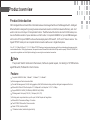
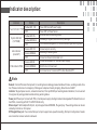
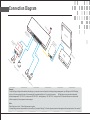
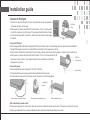
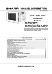
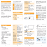
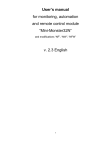
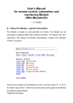
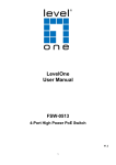
USER GUIDE
PoE & Optical Transmission
Intelligent managed PoE Switch
Statement
Copyright @ 2002-2013 Optical Network Video Technologies (Shenzhen) Co., Ltd
All Rights Reserved
This document contains proprietary information that is protected by copyright. No part of this document may be
reproduced, transmitted, transcribed, stored in a retrieval system, or translated into any language, in any form
or by any means, electronic, mechanical, magnetic, optical, chemical, manual or otherwise without the prior
written permission of Optical Network Video Technologies (Shenzhen) Co., Ltd.
®
is the registered trademark of Optical Network Video Technologies (Shenzhen) Co., Ltd. The information
and product specifications within this document are subject to change at any time, without notice and without obligation to notify any person of such change.
Packing List
Please kindly check the following items:
1 Intelligent managed PoE switch
1 Power Adapter
2 Mounting Kits
1 User Guide/Conformity Certificate/Warranty Card
!
Note
If any shortage or damage found, please contact us in time.
Product overview
Product Introduction
ONV Intelligent Ethernet Switch fills in that blank between Unmanaged Switch and Full Managed Switch. Intelligent
Ethernet Switch is designed for growing business network who needs to control their network effectively and don’t
want to cost more on full layer 2/3 complicated function. The Ethernet switch which is also built in PoE module provides an affordable solution of power and data over Cat.5 cable. It complied to IEEE802.3af, provide WEB management function of Priority and SNMP to achieve the idea deployment of Wilress AP, VoIP and IP based camera. Two
Gigabit TP/SFP combo port can complete the fast connection with server or Gigabit backplane.
24 or 16 10/100Mbps RJ45 port, 2 10/100/1000Mbps TP/SFP Combo port make growing business profits from outstanding perfermance and network extended function. The high perfermance, line-speed structure Ethernet Switch have Max 8.8Gbps switch capacity. All the 26/18 RJ45 Port
support auto- negotiation and Auto-Uplink technology for ensuring the correct network connection.
!
Note
The product ‘Switch’ mentioned in the manual, if without a special request, it is refering to 10/100M unmanaged PoE switch, PoE switch in short in below.
Feature
Complied to IEEE802.3af/at, 10Based-T, 100Based-T, 1000Based-T.
Web management function based on Web.
Provide PoE management, VLAN, Link Aggregation,QoS, MAC address binding and other intelligent management function.
Ethernet Port Rate: 24/16 self-adaptive 10/100Mbps and 2 self-adaptive 10/100/1000Mbps.
Support IEEE802.3af PoE (15.4Watts) or IEEE802.3at(30Watts)
PIN assignment: End-span(1/2+,3/6-), Mid-span (4/5+, 7/8-)
Working mode: asynchronization, point to point, full/half duplex self-negotiation.
Ethernet Port Transmission Range: 100meters
Two SFP GBIC Slot used for Fiber connection.
Cable: UTP 5E, Interface: RJ45
19’ standard cabinet, industrial high reliability.
Technical Structure and Port Description
275mm
275mm
44.5mm
44.5mm
440mm
440mm
E
A
B
D
C
POWER
B
ON
Intelligent Ethernet Switch
16 Port 10/100M+2 Port 10/100/1000M
ON
F
INPIT:100-240VAC
Freq:50/60Hz
OFF
A: Working LED indicator
B:16 Port PoE
C/D: Gigabit TP/SFP Combo Port
E: Local management port
F:100-240VAC,50/60Hz
D
C
POWER
F
INPIT:100-240VAC
Freq:50/60Hz
E
A
OFF
A: Working LED indicator
B:24 Port PoE
C/D: Gigabit TP/SFP Combo Port
E: Local management port
F:100-240VAC,50/60Hz
Intelligent Ethernet Switch
24 Port 10/100M+2 Port 10/100/1000M
Indicator description:
Indicator
Power Indicator: PWR
System Indicator
( SYSTEM)
Link indicator:
(Link/ACT)
Power ON, Normal Power Supply
OFF
Yellow LED ON
Power OFF or Power failure
Abnormal System Working Status
Yellow LED Blink
In Reading Program, Restore Factory Settings
OFF
1,Non-Network Management, 2, Abnormal WEB Program Working Status
Green LED ON
Connected port correctly
Receiving or Sending data
Green LED Blink
OFF
PoE indicator: POE
!
Description
Status
Yellow LED ON
Green LED ON
Connection failed or Abnormal Link
Connected standard PD, Normal Power Supply
Green LED Blink
Short Circuit or Over Load
OFF
No Connection or Connected PD is Non-Standard PD
Note
Remark: Internal Precision Component, for avoiding device damage please handles with case, avoiding violent vibration. Please contact us or local agency if damage or component loss by shipping, We will solve it ASAP.
Indicator: Support power source, network connection, Fiber port/RJ45 port working status indication, It is convenient
for engineer to parsing problem and monitoring working status.
Power port: Power port connect with PSU, internal power supply intelligent network management PoE switch are without PSU, connecting with AC110-245V/50Hz directly.
Ethernet port: Self-Adaption RJ45 port, all port support Auto MDIMDIX, Plug and play. The working status can be estimated by indicator on front panel.
SFP Gigabit fiber port: Two combo fiber port, all port support wire-speed forwarding, Rich port configuration. Seamless connection various network is allowed.
Detailed descriptions for the product model numbers
16-port Series POE switch
POE31016P: 16-port 10/100Mbps +2-port 10/100/1000Mbps up-link ( Combo Ethernet port & SFP slots ) switch , No. 1-16
ports support POE , IEEE802.3af, POE port output : 15.4watts , total power : 270watts
POE31016P-at: 16-port 10/100Mbps +2-port 10/100/1000Mbps up-link ( Combo Ethernet port & SFP slots ) switch , No.
1-16 ports support POE , IEEE802.3at, POE port output : 30watts , total power : 440watts
POE31016PM: 16-port 10/100Mbps +2-port 10/100/1000Mbps up-link ( Combo Ethernet port & SFP slots ) managed switch , No. 1-16 ports support POE , IEEE802.3af, POE port output : 15.4watts , total power : 270watts
POE31016PM-at: 16-port 10/100Mbps +2-port 10/100/1000Mbps up-link ( Combo Ethernet port & SFP slots ) managed
switch , No. 1-16 ports support POE , IEEE802.3at, POE port output : 30watts , total power : 440watts
24-port Series POE switch
POE31024P: 24-port 10/100Mbps +2-port 10/100/1000Mbps up-link( Combo Ethernet port & SFP slots ) switch , No. 1-24
ports support POE , IEEE802.3af, POE port output : 15.4watts , total power : 440watts
POE31024P-8at: 24-port 10/100Mbps +2-port 10/100/1000Mbps up-link ( Combo Ethernet port & SFP slots ) switch , No.
1-24 ports support POE , No. 1-8 ports support IEEE802.3at, No. 9-24 ports support IEEE802.3af , total power : 440watts
POE31024PM: 24-port 10/100Mbps +2-port 10/100/1000Mbps up-link ( Combo Ethernet port & SFP slots ) managed switch , No. 1-24 ports support POE , IEEE802.3af, POE port output : 15.4watts , total power : 440watts
POE31024PM-8at: 24-port 10/100Mbps +2-port 10/100/1000Mbps up-link ( Combo Ethernet port & SFP slots ) managed
switch , No. 1-24 ports support POE , No. 1-8 ports support IEEE802.3at, No. 9-24 ports support IEEE802.3af , total power :
440watts
Tel:+86-755-33376606 Fax:+86-755-33376608 Email:[email protected]
Address: Room 1003, Block D , Tairan building , Chegongmiao, Futian district ,Shenzhen ,China
Factory address:No 5, A building, SenYuTai S&T park, Longhua road, BaoAn district,Shenzhen, China
www.onvcom.com
Connection Diagram
AC
Po
PO E S
E 3 w it
10
c
24 h
PM
ap
te
r
M
F ib
co er
nv me
er
t e d ia
r
PoE
IN
Po
PD E Sp
3 1 li t
01 ter
Ad
IN
PoE
RUN
Ca
on
ito
r
ON
OFF
:12V
:5V
t .5
Pow
Pow
PD-
er
ove
ered
r Eth
ern
et
Spl
itte
Ethe
OUT
ice
Dev
r
rne
t out
DC
RUN
DC
T
OU
Ca
t .5
Ca
DC
IP
Ca
m
er
OU
T
t .5
NV
R
V id
eo
li n
e
a
Po
EI
PC
am
er
a
Po
EI
PC
am
er
a
Po
EI
PC
am
er
a
Remark :
Via the Web login configuration interface and web page , you can set various configuration including exchange management, port Settings and VLAN Settings,
and so on.You can use a web browser (it is recommended to use Internet Explorer 5.0 or above) to operate.
All Ethernet ports support web management ,
default management IP: 192.168.2.1, subnet mask :255.255.255.0, default gateway: 192.168.2.254. As long as the PC of the administrator can communicate
with this equipment , this equipment can be managed .
Note:
Default login user: admin Default login password: system.
Corresponding user name and password can be modified in” password Settings”. For details, please see network management software applications "user manual"
Installation guide
Connect to RJ45 port
1.Connect one end of RJ45 wire to switch, the other end to other equipment, as
shown as the figure on the right;
2.After power on, please check the LED indictor status. If it is on, it shows the
link is OK, otherwise, the link is down. Then please check the link and make
sure the other equipment is turned on, refer to the instruction on above page
for details.
Rj45 port
Plug
Connect to SFP port
Smart managed PoE switch has 2 independent SFP ports. Please refer to the following steps for optical module installation.
1.Grasp SFP module and insert it in switch SFP slot smoothly till they keep close contact;
2.Insert one end of the fiber to the Rx and Tx accordingly, and the other end to other equipment, shown as in the right figure;
3.After power on, please check the LED indictor status. If it is on, it shows the link is OK,
SFP Port
otherwise, the link is down. Then please check the link and make sure the other
Fiber module
equipment is turned on.
Connect to power
Smart managed PoE switch adopts AC 100-240V, 50/60Hz.
1.Please check the power supply specification matches with the required;
2.Connect switch power wire to AC power socket, shown as in the following figure.
Optical Fiber
L Angle Iron
Screw
Power Supply Connection Figure
Mounting Kits Installation Figure
Rack Installation Figure
After installation, please check:
If there is enough space for heat sink; if the power socket is suitable for switch specification; if the power, switch and rack are
properly grounded and if the connection between switch and other network equipments are normal.