1
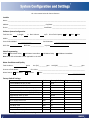
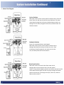
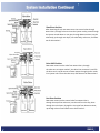
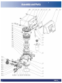
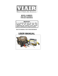
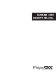
System Configuration and Settings 2 Product Features and Application 3-4 Product Dimensions and Specifications 5 Pre-Installation Check-list 6 Programming Instructions 7 Valve Installation 8 System Installation 9-15 Assembly Drawings and Parts List 16-17 Troubleshooting 18-20 Replacement Parts 21 Packing List 22-23 Warranty 24 Contact Information 25 Fill in the content below for future reference. Installer Name: _________________________________________________________________________________________________ Address: _____________________________________________ City/State: _________________________________________ Phone: ____________________________________________ Install Date: __________________________________________ Softener System Configuration Tank Size: Dia. in, Height in Resin Volume: cu/ft. Brine Tank Capacity: 80L 100L 130L Media: _________________________________________________________________________________________________ Control Valve Model: _____________ DLFC Size: Serial Number: BLFC Size: ________________ Injector: ______________________________ ______ Valve Programming Mode: A-01 Meter Delay A-02 Meter Immediate A-03 Meter Delay A-04 Meter Immediate Note: A-03 and A-04 modes are not applicable in the USA Water Conditions and Quality Total Hardness: grains Pressure of Inlet Water: Water Source: Well Water Iron (Fe): _________ppm Acid (pH): ____________ TDS: ___________ppm PSI Other: __________________________________________________________ City Water Other: _______________________________ _______________ Factory Default Settings Parameter Unit Factory Default Programmed Settings Control Mode A-01 (02, 03, 04) / A-01 Unit Mode HU01 (02, 03) / HU01 3 Water Treatment Capacity (Meter type) m 80 Operation Days (Time clock type, by days) D 03 Operation Hours (Time clock type, by hours) H 20 Regeneration Start-up Time / 02:00 Backwash Time Min. 10 Brine & Slow Rinse Time Min. 60 Brine Refill Time Min. 05 Fast Rinse Time Min. 10 Interval Regeneration Days D 30 Output Mode b-01 (02) / b-01 2.56gpm drain line flow control, .30gpm brine line flow control and blue injectors are factory installed. Primary Applications Recommended for residential applications. ● Softening System ● Iron Removal System ● Ion Exchange Equipment ● Boiler Softening Water Treatment ● RO Pre-treatment Product Characteristics ● Reliable Design The RevV2 uses hermetically sealed ceramic discs which are corrosion and abrasion resistant. Rotation of the upper disc aligns to the corresponding lower disc ports for Service, Backwash, Brine & Slow Rinse, Brine Refill and Fast Rinse modes. ● No Hard Water Bypass No hard water bypass option is available upon request. Stocked valve is a hard water bypass with exception during backwash cycle, no hard water is allowed to bypass thru the valve. ● Manual Regeneration Regeneration can be initiated manually after unlocking the keypad and pressing . You may also advance through each phase by pressing . ● Power Outage Indicator If outage exceeds 3 days, the time of day indicator “” will flash 12:12. The current time of day needs to be re-set. All other set parameters remain stored in memory. The valve will continue to process from the point of the power outage. ● Lockout Function Keypad will lock after 1 minute without use. In order to access the parameter changes press and hold and simultaneously for 3 seconds to unlock. ● LED Display Screen The strips on the screen flash from bottom to top indicating service mode is activated. ● Automatic Regeneration Interval Set maximum number of days between regenerations. ● Interval Backwashes This is an optional setting for applications requiring more than 1 backwash. ● Interlock Function The interlock function allows for one valve to be in regeneration while the other valves are in service, so multiple valves are running parallel or in series. Refer to Figure 3-9 ● Remote Handling Input This connector can receive an external signal to be used with a PLC or computer in order to control the valve. Refer to Figure 3-11 ● Pressure Relief Output The valve cuts off water to the drain line when it switches into regeneration (Same as signal output b-02) for water treatment systems where the inlet pressure rises too fast, which can damage the valve, Pressure Relief Output can be used. An application example is a deep well system where a booster pump has been installed on the inlet to increase the water feeding pressure. Refer to Figure 3-10 ● Maximum Day Regeneration When the valve reaches the maximum set days, even when maximum volume has not been reached, the valve forces a regeneration at the pre-programmed time of day. ● Regeneration Mode Options with Adjustable Phase Times Mode Name Instruction Regenerate on the day the available volume of treated water drops to zero (0). A-01 Meter Delayed Regeneration starts at the regeneration time set. Regenerate immediately when the available volume of treated water drops to A-02 Meter Immediate zero (0). Intelligent Meter Delayed The valve calculates the system capacity; set the Resin Volume, Feed Water Not Applicable for U.S. A-03 Hardness, and Regeneration Factor. Regeneration starts at the regeneration Customers time set. Intelligent Meter Immediate Set the Resin Volume, Feed Water Hardness, and Regeneration Factor; the valve Not Applicable for U.S. A-04 calculates the system capacity and regenerates when capacity is reached. Customers ● Time Clock Regeneration Option Adjust the maximum interval regeneration days to the number of days for regeneration. ● Signal Output There are two kinds of output modes: b-01 Mode: Signal turns on at start of regeneration and shuts off at end of regeneration. b-02 Mode: Signal available in intervals during regeneration cycles and during In Service. There is a signal output connector on the main control board for controlling external devices. Refer to Figure 3-1 to Figure 3-8. b-01 b-02 Model Length(max) Width(max) Height (max) Regeneration Mode RevV2 8.0” 7.0” 8.0” Down-flow The valve dimensions are for reference only. Connect Port Dimensions Product Model Inlet Port Outlet Port Drain Port Brine Port Base Riser Pipe Hard Water Bypass RevV2-HW 1” NPT 1” NPT 1/2” NPT 3/8” 2.5”-8NPSM 1.05” Yes RevV2-NHW 1” NPT 1” NPT 1/2” NPT 3/8” 2.5”-8NPSM 1.05” No Main Technical Parameters Water Capacity 10 gpm (15psi Pressure Drop) Power Input Power Output AC100~240V/50~60Hz 12VDC/1.5A Regeneration Sequence Service → Backwash → Brine & Slow Rinse → Brine Refill → Fast Rinse. Regeneration Mode A-01 Meter Delay: Regeneration happens when the capacity reaches zero and the preset time of regeneration is reached. A-02 Meter Immediate: Regeneration happens when the capacity reaches zero. A-03 Intelligent Meter Delay: The valve calculates the system capacity; set the Resin Volume, Feed Water Hardness, and Regeneration Factor. Regeneration starts at the regeneration time set. A-04 Intelligent Meter Immediate: Set the Resin Volume, Feed Water Hardness, and Regeneration Factor; the valve calculates the system capacity and regenerates when capacity is reached. Before installation, read through this manual thoroughly. Then obtain all materials and tools needed for installation. This softening system will operate at maximum efficiency when the following conditions are considered. Required Revv2 Operation Conditions: Working Conditions Working Environment Inlet Water Quality Working pressure 21psi to 120psi Water temperature 40 °F - 120 °F (5℃ - 50℃) Environment temperature 40 °F - 120 °F (5℃ - 50℃) Relative humidity ≤ 95%(When temperature is 25℃/77°F) Power source AC100~240V/50~60Hz Turbidity Down-flow regeneration<5FTU Hardness 1 grain per gallon (gpg) = 17.1 parts per million (ppm) Chlorine <0.1ppm Iron 2+ <0.3ppm ● All plumbing and electrical work should be performed by an accredited professional to ensure all local, state, and municipal guidelines are met. ● Do not use the control valve with water that is unsafe or of unknown quality. ● Do not use the brine tube, injector body, or other connectors on the RevV2 valve as a handle to carry the system. ● Ensure there is salt in the brine tank at all times when this valve is used for softening. The brine tank should contain clean water softening salts only, at least 99.5% pure. Do not use small grain salt. ● When there is moderate to high turbidity, a filter should be installed before the water softening system on the inlet side. ● If the water pressure exceeds 120psi, a pressure reducing valve must be installed before the water inlet. If the water pressure exceeds 80 psi, installing a pressure reducing valve before the water inlet is highly recommended. If the water pressure is under 21psi, a booster pump must be installed before the water inlet. ● Replacement parts for the RevV2 valve should only be purchased through Hankscraft H20 Products resellers. Electrical components such as transformers are specific to the RevV2 valve from Hankscraft. ● Regular interval monitoring of the water quality and work environment is recommended to insure proper operation of the valve and system. ***Failure to use this product within the described conditions may void the warranty*** ● Programming Key Time of Day Indicator LED, displays the time of day. LED flashes, reset the time of day after electrical service has been interrupted for 3 days or more. Button Lock Indicator LED on, indicates the buttons are locked. To unlock, press and hold both and buttons simultaneously for 5 seconds until the LED turns off. Program Mode Indicator LED on, enter program display mode. Use or buttons to view all values. LED Flashes, enter program set mode. Press or buttons to adjust values. Menu/Confirm Button Press , the LED turns on; enter program display mode, press or to view all values. In program display mode, press , the LED flashes; enter program set mode and press or to adjust the values. Press after all program features are set. Manual /Return Button Press the button in any status and the valve will proceed to the next step. (Example: Press the button while the valve is in Service status and it will start a manual regeneration. Press the button while in Backwash status and the valve will go to Brine & Slow Rinse instantly.) Press the button in program display mode and it will return to In Service. Press the button in program set mode and it will return to program display mode. Press the while adjusting the value and it will return to program display mode directly without saving value. Down and Up Buttons In program display mode press or buttons to view all values. In program set mode press or buttons to adjust values. Press and hold both and buttons simultaneously for 5 seconds to unlock the programming functions. Installation Notice Before installation, read through this manual thoroughly and obtain all materials and tools needed for installation. All plumbing and electrical work should be performed by an accredited professional to ensure all local, state, and municipal guidelines are met. Unit Location The filter or softener should be located close to a floor drain away from direct sunlight and any heat sources. Ensure the unit is installed with enough space for operation and maintenance. The installation surface should be clean and level. Install the unit in an environment which minimizes consumer impact in the event of malfunction. Brine tank should be installed close to the RevV2 control valve. Control Valve Installation 1.05” riser pipe with bottom basket is inserted into the center of the mineral tank. Install Valve Base O-ring around the neck of the valve. Lubricate the center hub O-ring of the RevV2 valve. Install the top basket with a twist and lock action to center hub of the RevV2 valve. Place RevV2 valve onto tank with the distributor tube inserted down the middle of the basket. Rotate clockwise to secure onto the tank. Figure 1-1 Bypass Installation Note: Before attaching the bypass to the valve, verify meter is installed in outlet side of the bypass with the propeller facing in. As Figure 1-2 shows; install the seals into the animated connector. Attach animated connectors to the inlet/outlet and grease the O-rings. Attach the bypass valve and insert the clips. Meter cable is installed into cable port on the outlet side during system start-up, see page 12. Figure 1-2 Plumbing Connections As Figure 1-3 shows; connect inlet pipe with inlet connector of bypass via 1” NPT female connector. Connect outlet pipe with outlet pipe of bypass via 1” NPT female connector. Figure 1-3 Drainline Installation As Figure 1-4 shows; install drain line with an air gap to the floor drain. An air gap is required between the drainline and the drain (sewer). This avoids a syphon effect and reverse contamination. Figure 1- 4 Brineline Connection As Figure 1-5 shows; slide brine nut onto the 3/8″ brine tubing. Install the filter screen into the ferrule and insert the ferrule into the end of brine tube. Insert tube into brine connector and secure brine nut to the brine connector. Figure 1-5 Brine Tank Installation Remove cap from brine well. Remove overflow nut and float. Adjust float to the proper salt line. Use a twist and pull action to slide upper rubber stopper to desired position. Note: Hold float rod securely to not pull from air check assembly. Repeat with lower rubber stopper to secure float in position. Refer to Figure 1-8. 9x48 to white tape or above 10x44 to blue tape or above 10x54 to blue tape or above 12x52 to green tape or above Secure brine well to brine tank with the overflow elbow and nut using the lower hole. Refer to Figure 1-7. Replace brine float into brine well. Insert brine line tubing through the upper hole of tank and well. Refer to Figure 1-6. Slide brine line nut onto brine line, insert line into well, and secure nut to well. Replace brine well cap. Attach a drain tube to the overflow elbow. Maintain an air gap between the tube and floor drain. Drain Overflow Elbow Figure 1-6 Figure 1-7 Figure 1-8 System Installation Chart System Start-up Before running the RevV2 for the first time, flush out the water line and bypass. Be sure the bypass is closed. Turn the water source on at the inlet to the house. Disconnect the bypass from the RevV2 valve if attached to the valve. Be sure to remove the meter impeller from the bypass before opening the bypass. Put a container under the bypass and open the bypass to allow water to flow through and remove any foreign material out of the water lines. Close the bypass. Reinstall the meter impeller in the outlet side with the impeller facing in and re-connect the bypass to the valve. Open the bypass. Check for any leaks. Insert meter cable in the outlet side of the bypass or connector, the side the impeller is installed in. Plug in the power cord for the valve. Open a water line and let water flow until water runs clear. Press and hold both and buttons simultaneously for 3 seconds to unlock the key pad. Press to advance to 2 - Backwash; this lets air out of the drain line. Verify the air check valve is closed by listening to be sure no air is being drawn into the system. Process will take 8-10 minutes to purge the system. Note: when you press the screen will display “-00-” as it positions the ceramic discs. Once “-00-” disappears and the next phase is displayed, you can press Press to advance to the next phase. to manually advance through the next phase, 3 - Brine & Slow Rinse. Verify the air check valve is closed by listening to be sure no air is being drawn into the system. Press to manually advance to the next phase, 4 - Brine Refill. This phase will fill the brine tank with the correct amount of water. Allow the brine refill phase to run, do not advance past this phase. Should take about 10 minutes for a 1 cu/ft. system. After this phase has completed, press to manually advance to 5 - Fast Rinse and again to advance to the Service position. Next add salt to the brine tank. (40lb minimum, 120lb maximum) Note: We recommend using pellet salt, NOT solar salt. Install brine tank cover. Turn a faucet on, away from the installation location, until the water from the plumbing lines has been purged. Softening system is now fully operational. Take a water sample to verify and test for hardness reduction. Sanitizing Procedure At the start up or after a period of one week the following procedure is recommended to remove the possibility of bacterial growth or contamination within the system. This procedure relates only to the original description of equipment and options described for this system. Any alterations to the configuration would require evaluation by a trained water professional. Remove the brine tank cover and locate the brine well. Remove the brine well cap. Pour 1/3 cup of unscented bleach into the brine well. Place cap back on brine well and cover back on brine tank. The system must be regenerated. Select an immediate regeneration or a delayed regeneration. a) Immediate Regeneration: At the control valve, press and and hold for 3 seconds to unlock the valve. Press to start an immediate regeneration. Allow approximately 2 hours for the valve to complete its regeneration cycle and to return to service mode. b) Delayed Regeneration: At the control valve, press and hold for 3 seconds to set a delayed regeneration that very next morning at the programmed time. (Default setting is 2:00am) Water Flow Diagram Service Position Raw water enters into the control valve from water inlet A, from the top of valve core and into the tank from top distributor. The water moves down through the resin layers, through bottom strainer, up through the riser tube, through the valve core, and then flows out of water outlet B. Backwash Position Set to 0 for standard softeners and skipped. Raw water enters into the control valve from water inlet A, through valve body from the top of valve core, then from the bottom of tank through the riser tube, into the valve core, and finally flows out of drain outlet C. Brine Draw Position Raw water enters into control valve from water inlet A, through valve core into injector inlet F, into the injector outlet E. This produces negative pressure so the brine is drawn into the valve. Water flow then goes into the riser pipe, through the bottom strainer into the tank, up through resin layer, valve core, and then flows out drain outlet C. Slow Rinse Position After absorbing all salt, raw water enters into control valve through water inlet A, through valve core into the injector nozzle, passes through the injector nozzle down to riser pipe, through bottom strainer, into the valve body, up through resin layer, into valve body, valve core, and flows out of drain outlet C. Brine Refill Position Raw water enters into the valve from water inlet A, through the valve core to injector outlet E, into brine line connector D, and fills the brine tank. A small amount of water passes through injector outlet E to injector inlet F from the valve core, and flows out of drain outlet C. Fast Rinse Position Raw water enters into the control valve from water inlet A, through the top of the valve core, into the tank from the top, down through the resin layers, through the riser pipe from bottom strainer, up through valve core and flows out to drain outlet C. Item No. 1 2 3 4 5 6 7 8 9 10 11 12 13 14 15 16 17 18 19 20 21 22 23 24 25 26 27 28 Description Valve Body O-ring 73 × 5.3 Inner D-tube O-ring 25.8 × 2.65 Valve Body (ABS + GF10) Valve Body (ABS + GF20) Screw, Cross ST 3.9 × 16 Screw, Cross M 4 × 30 Motor Small Gear Pin Wire for Power Cable Clip Screw, Cross ST2.2X6.5 Label Front Cover Display Board Wire for Display Board Control Board Wire for Locating Board Dust Cover Probe wire Screw, Cross ST2.9X16 Screw, Cross ST3.9X13 Big Gear, Driven Screw, Cross ST2.9X9.5 Locating Board Fitting Nut O-ring 73X3.55 O-ring 37.7X3.55 Anti-friction Washer Quantity 1 1 1 1 4 4 1 1 1 1 2 4 1 1 1 1 1 1 1 1 3 1 1 7 1 1 2 2 1 Item No. 29 30 31 32 33 34 35 36 37 38 39 40 41 42 43 44 45 46 47 48 49 50 51 52 53 54 55 56 Description Shaft Moving Seal Ring Moving Disk Fixed Disk Seal Ring Hexagonal Nut Tube Net O-ring 11X2 Seal Ring Plug Animated connector Connector Connector Brine Line Flow Control Drain Line Flow Control O-ring 15X1.8 Clip Screw, Cross M5X35 Injector Cover Filter net Nozzle, Injector O-ring 8X1.8 Throat, Injector O-ring 30X1.8 Injector Body O-ring 7.5X1.8 O-ring 10.82X1.78 Quantity 1 1 1 1 1 1 1 1 1 1 1 1 1 1 1 1 1 1 2 1 1 1 1 1 1 1 2 1 Control Valve Problem 1. Softener fails to regenerate 2. Regeneration time is not correct 3. Hard water 4. Softener fails to draw brine 5. Unit uses too much salt 6. Excessive water in brine tank Cause A. Electrical service to unit has been interrupted. B. Regeneration cycles set incorrectly. C. Controller is defective. D. Motor failure. A. Time of Day not set correctly. B. Power failure over 3 days. Correction A. Check for consistent electrical service. A. Bypass valve is open or leaking. B. No salt in brine tank. F. Internal valve leak. G. Regeneration cycles not correct. H. Shortage of resin. I. Bad quality of feed water or meter blocked. A. Close or repair bypass valve. B. Add salt to brine tank and maintain salt level above water level. C. Change or clean injector. D. Check brine tank refill time. E. Make sure riser pipe is not cracked. Check O-ring and tube pilot. F. Change valve body. G. Set correct regeneration cycles in the program. H. Add resin to mineral tank and check for leaks. I. Reduce the inlet turbidity, clean or replace meter. A. Line pressure is too low. B. Brine line is plugged. C. Brine line is leaking. D. Injector is plugged. E. Internal leakage. F. Drain line is plugged. G. Wrong BLFC, DLFC and injector. A. Increase line pressure. B. Clean brine line. C. Replace brine line. D. Clean or replace injector. E. Replace valve body. F. Clean drain line flow control. G. Install properly sized BLFC, DLFC & injector. A. Improper salt setting. (Brine refill time) B. Excessive water in brine tank. A. Brine refill time is too long. B. Foreign material in brine line. C. Foreign material in brine valve or plugged drain line flow control. D. Power outage during brine fill. A. Check salt usage and salt setting (brine refill time). B. See problem no.6. A. Reset correct refilling time. B. Clean brine line. C. Clean brine valve, and DLFC. C. Injector plugged. D. Insufficient water level in brine tank. E. Leak at O-ring on riser pipe. E. Safety valve in brine tank malfunction. A. Iron in the water supply pipes. B. Iron mass in the softener. 7. Pressure lost or iron in conditioned C. Fouled resin bed. water D. Too much iron in the raw water. A. Air in water system. 8. Loss of mineral through drain line B. Bottom strainer broken. C. Improperly sized drain line control (DLFC). B. Reset regeneration cycles. C. Replace controller. D. Replace motor. Check program and reset time of day. D. Put the valve in bypass. Install a safety float in brine tank. E. Repair or replace brine safety valve. A. Clean the water supply pipe. B. Clean valve and add resin cleaning chemical, increase frequency of regeneration. C. Check backwash, brine draw and brine tank refill. Increase frequency of regeneration and backwash time. D. Install Iron removal equipment before softening. A. Assure that well system has proper air eliminator control. B. Replace bottom strainer. C. Check for proper drain rate. Problem 9. Control cycles continuously 10. Drain flows continuously 11. Interrupted or irregular brine 12. Water flows from drain or brine line after regeneration 13. High concentration of brine 14. Decreased Capacity 15. Power Outage Occurs During Regeneration Cause A. Signal to the locating PCB is interrupted. B. Controller is faulty. C. Foreign material in the drive gear. D. Time of regeneration steps were set to zero. A. Internal valve leak. B. Interrupted power supply during backwash. A. Water pressure too low or not stable. B. Injector is plugged or faulty. C. Air in resin tank. Correction A. Check the connection between the main PCB to the locating PCB. B. Replace controller. C. Remove blockage in drive gear. D. Check program setting and reset. A. Check and repair valve body or replace it. B. Adjust valve to service position or turn off bypass valve and restart when power is restored. A. Increase water pressure. B. Clean or replace injector. C. Check and find the reason. A. Foreign material in the valve body. B. Hard water mixed in valve body. C. Water pressure is too high. A. Clean foreign material in valve body. B. Change valve core or sealing ring. C. Reduce water pressure or use pressure release function. A. Foreign material in injector. B. Brine valve cannot be shut-off. C. Rapid rinse time is too short. A. Regeneration is not occurring. B. Fouled resin bed. A. Clean and repair injector. B. Replace brine valve or clean it. C. Extend rapid rinse time. A. Reset regeneration parameters. B. Increase backwash flow rate and time, clean or change resin. C. Readjust brine draw time and adjust float height. C. Safety float is not at the proper height or brine time is low. D. Softener setting not proper. E. Raw water quality has altered. F. Flow meter is slow or stationary. A. System locked in current phase/cycle. D. Re-test the water and change the valve parameters. E. Regenerate unit manually then reset regeneration cycle. F. Disassemble and clean flow meter or replace. A. Close the bypass until power resumes. If power outage last over 72 hours, the time of day will need to be reset. Electronics Problem 1. Abnormal display 2. Blank display 3. E1 code 4. E2 code 5. E3 or E4 code Cause Correction A. Wiring to the front panel is loose. B. Control board is faulty. C. Transformer malfunction. D. Electrical service unstable. A. Check and replace the wiring. B. Replace control board. C. Check and replace transformer. D. Verify power source. A. Wiring to the front panel is loose. B. Front panel damaged. C. Control board damaged. D. Electricity is interrupted. A. Wiring of locating board with controller fails to work. B. Locating board damaged. C. Mechanical drive failure. D. Faulty control board. E. Wiring to the motor has a short. F. Motor damaged. A. Hall effect on locating board damaged. B. Possible short in the wiring to the locating board. C. Control board is malfunction A. Control board malfunction A. Check and replace wiring. B. Replace front panel. C. Replace control board. D. Check power source. A. Replace wiring. B. Replace locating board. C. Replace Discs or drive gear. D. Replace control board. E. Replace wiring. F. Replace motor. A. Replace locating board. B. Replace wiring. C. Replace control board. A. Replace control board. Replacement Parts Description Transformer, 12VDC Upper Distributor Basket Part Number 6379021 116044H Bypass Clips Drain Assembly Kit - #40, #42, #45, #46 DLFC Buttons, BLFC Buttons, & Injector Kit with plugs Brine Assembly Kit, 3/8” - #34, #35, #36, #37, #41 Brine Screen and Tube - #35, #36 Locating Board Kit - #17, #23, #24 Display Board Kit - #11, #14, #15 Meter Cable Assembly Kit - #10, #19 Motor - #6 O-ring, Valve Center Hub - #2 O-ring, Valve Body - #1 Injector Cover O-ring - #53 Injector Filter Screen Kit - #49, #51 Injector Body Assembly Kit - #34 - 56 8270004 REVV-216 REVV-215B REVV-217 REVV-218 REVV-228 REVV-226 REVV-232B 6158012 8378078 8378143 8378025 REVV-219 REVV-220B Quantity 1 EA 1 EA 1 EA 1 KIT 1 KIT 1 KIT 1 EA 1 KIT 1 KIT 1 KIT 1 EA 1 EA 1 EA 1 EA 1 KIT 1 KIT Valve Packing List Description Part Number Figure Control Valve F63-C3 1 12V DC Transformer 6379021 1 User Manual Quantity 1 Parts Valve Base O-ring 8378143 1 Interlock Cable 5515002 1 Washers 8371001 2 Filter Screen & Bushing 8336008 / 8457039 3/8” Brine Nut 8940001 Injector Nozzle, Throat & Plug (plugs not pictured) 1 Set 1 Injector and Button Kits – REVV215B 6301, 6302, 6303, 6304, 6305, 6306, 6307, 6308, 6309, 6310 1 Set Drain Line Flow Controls 8468042 8468044 8468060 8468062 8468043 8468045 8468061 8468063 1 Set Brine Line Flow Controls 8468052 8468054 8468056 8468053 8468055 8468057 1 Set System Packing List Description Part Number Quantity RevV2 Control Valve 1” Push Pull Bypass Pressure Tank and Media (media may be installed in tank or bulk separate) Distributor Tube and Lower Basket (installed in pressure tank) Upper Basket Brine Tank and Float Assembly 3/8” Brine Line Customer Manual F63-C3 41204B Varies with system size Varies with system size 116044H Varies with system size BL3/8 --- 1 1 1 1 1 1 4’ 1 Warranty Card --- 1 Limited Warranty As described herein, Hankscraft Inc., d/b/a H20 Products (“Hankscraft”), warrants its’ products are free from defects in material and workmanship only, when properly installed, operated, and maintained. This warranty is subject to the exceptions herein. Hankscraft warrants to the original owner that the items listed below will be free from defects in materials and workmanship for the period of time specified below from the original purchase date. Control valve and all internal valve parts and the salt storage tank – FIVE YEARS Mineral tank – TEN YEARS Any other component – ONE YEAR Mineral tank media/resin is not warrantied. Any parts used for replacement are warrantied for the remainder of the original warranty period applicable to the part from the date of manufacture. Hankscraft’s obligation by this Limited Warranty, at is option, is to repair or replace any warrantied product only. Prior to returning the product to Hankscraft, a valid return materials authorization number must be obtained from Hankscraft. Any product returned to Hankscraft without a valid return authorization number will be rejected. Any product found to be defective will, at the sole discretion of Hankscraft, be repaired or replaced. Hankscraft is not responsible for shipping cost to the repair facility. This section lists the sole remedies for any valid warranty claim. This warranty does not apply to defects reported to Hankscraft outside of the warranty period. This warranty does not apply to defects caused by installing, operating, servicing, modifying, repairing or maintaining (or lack of maintaining) the product outside of Hankscraft’s recommendations. This warranty does not apply to defects caused by damage during shipment, neglect, misuse, modification, accident, noncompliance with local codes and ordinances, hot water, frozen water, sediment, corrosive liquids, gases, chemicals, bacteria, animals, sand, salt, flood, wind, fire, outdoor installations where the product is not reasonably covered, pneumatic use, or acts of God. No other person is authorized to make any other warranty on behalf of Hankscraft either during or after the applicable warranty period. Hankscraft assumes no liability for determining the proper products and equipment or installation necessary to meet the requirements of the user of the product, and Hankscraft does not authorize others to assume such liability on its behalf. THE WARRANTIES AND REMEDIES HEREIN ARE EXCLUSIVE AND IN LIEU OF ANY AND ALL OTHER WARRANTIES OR REMEDIES EITHER EXPRESSED OR IMPLIED, HEREIN OR ELSEWHERE, INCLUDING WITHOUT LIMITATION WARRANTIES OF MERCHANTABILITY, FITNESS FOR ANY PARTICULAR PURPOSE, NON-INFRINGEMENT OR WARRANTIES RESULTING FROM COURSE OF PERFORMANCE, COURSE OF DEALING OR FROM USAGE OF TRADE. HANKSCRAFT HEREBY DISCLAIMS ALL OTHER WARRANTIES. HANKSCRAFT’S LIABILITY SHALL NOT EXCEED THE COST OF THE PRODUCT. HANKSCRAFT IS NOT RESPONSIBLE FOR INCIDENTAL OR CONSEQUENTIAL DAMAGES OR EXPENSES OF ANY KIND WHATSOEVER, INCLUDING LOSS OF PROFITS, UNDER ANY CIRCUMSTANCES AND REGARDLESS OF WHETHER HANKSCRAFT WAS AWARE OF THE POSSIBILITY OF ANY SUCH LOSS. Thank you for choosing this elements by Hankscraft water treatment system. Please contact your service professional with any questions. Updated February 2014