1
Quick Start Guide: QUBE-Servo USB Interface
STEP 1 Check Components and Details
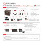
Make sure your QUBE-Servo experiment includes the following components:
1
4
3
2
1. Quanser QUBE-Servo
USB Interface
2. Inertia disc module
3. Pendulum module
5
6
4. USB 2.0 A/B cable
5. 15V 2.0 A power supply
6. Power cable
7. Instructor Workbook*
8. Student Workbook*
7
9
8
9. User Manual*
QUbE-Servo Experiment for MATLAb /Simulink Users
Qube-Servo experiment for MAtLAb /Simulink users
Student Workbook
uSer MaNuaL
Standardized for ABET * Evaluation Criteria
Standardized for ABET * Evaluation Criteria
Set Up and Configuration
Developed by:
Jacob Apkarian, Ph.D., Quanser
Michel Lévis, M.A.SC., Quanser
Developed by:
Jacob Apkarian, Ph.D., Quanser
Michel Lévis, M.A.SC., Quanser
INSTRUCTOR WORkbOOk
QUBE educational solutions
are powered by:
QUBE educational solutions
are powered by:
Course material
complies with:
Course material
complies with:
CApTIvATE. MOTIvATE. GRAdUATE.
*Provided in digital form on the Workstation Resources DVD and online at
www.quanser.com/courseware
Captivate. Motivate. Graduate.
CAptivAte. MotivAte. GrAduAte.
*ABET Inc., is the recognized accreditor for college and university programs in applied science, computing, engineering, and technology, providing leadership and quality assurance
in higher education for over 75 years.
QuBe-Servo experiment
Solutions for teaching and research. Made in Canada.
*ABET Inc., is the recognized accreditor for college and university programs in applied science, computing, engineering, and technology, providing leadership and quality assurance
in higher education for over 75 years.
STEP 2 Additional Components Required for Set Up
Ra
p
Ra
p
Use
QU
AR
CR
ea
l-T
im
e
Use
QU
AR
CR
ea
l-T
im
e
Ra
p
Use
QU
AR
CR
ea
l-T
im
e
tion.
rma
info
for
TO SET UP QUANSER
TO SET
WORKSTATIONS
UP QUANSER WORKSTATIONS
For use with
For MATLAB®/Simulink®
On this DVD:
• Quick start Guides
• Pre-designed Controllers
• User Manuals
• Instructor and Student Workbooks
or Laboratory Guides
R2011a,b and R2012a,b
For installation procedure please
For installation procedure please
refer to the Installation Guide on this DVD.
refer to the Installation Guide on this DVD.
For assistance, contact [email protected]
For assistance, contact [email protected]
©2
©2
m
om
013
013
.co
er.c
Qua
sear
nu
aQ
ans
nser
nser
w.qu
w.qu
Inc. All
Inc. All
rights reserved. ww
rights reserved. ww
RESOURCES DVD
om
r.c
se
an
qu
RESOURCES DVD
tion.
rma
info
for
For MATLAB®/Simulink®
R2011a,b and R2012a,b
control over 80 Quanse
control over 80 Quanse
r exp ftware to
r exp
are to
oftw
o
erim
gS
g Serimen
ent
pin
pin
ts.
s. C
oty
oty
Co
on
rot
rot
nta
tac
lP
lP
ct
ro
ro
t in
inf
nt
nt
fo
o@
Co
Co
@
id
id
2
om
r.c
se
an
qu
REAL-TIME RAPID
REAL-TIME
CONTROL
RAPID CONTROL
PROTOTYPING SOFTWARE
PROTOTYPING
v2.3SOFTWARE v2.3
.
tion
rma
info
for
SOFTWARE INSTALLATION
SOFTWARE
DVD INSTALLATION DVD
.
tion
rma
info
for
Use
QU
AR
CR
ea
l-T
im
e
control over 80 Quanser
control over 80 Quanser
expe ftware to
expe
are to
oftw
or
rim
gS
g S iment
ent
pin
pin
s. C
s. C
oty
oty
on
on
rot
rot
tac
tac
lP
lP
t in
t in
ro
ro
nt
nt
fo
fo
@
@
Co
Co
q
q
id
m
.co
er
ns
ua
id
m
.co
er
ns
ua
1
Ra
p
To complete the Quanser QUBE-Servo USB Interface set up, you will also need the following:
©2
013
Qua
nser I
nc. Al
For use with
On this DVD:
• Quick start Guides
• Pre-designed Controllers
• User Manuals
• Instructor and Student Workbooks
or Laboratory Guides
m
©2
om
01 er.co
er.c
an3s Quan
ans
ser Inc
w.qu
w.qu
. All rights reser ved. ww
l rights reser ved. ww
1. QUARC Real-Time Rapid Control Prototyping
Software Installation DVD*
2. Quanser Workstations Resources DVD
(includes controllers, User Manual, Quick Start
Guide, courseware and other files)
*QUARC software must be purchased separately
STEP 3 Install and Test QUARC
A. Make sure you have all required software, as listed in the QUARC Compatibility Table document located in the
QUARC DVD folder.
B. See the QUARC Installation Manual for details on how to install the software.
C. Make sure you test the system using the Sine and Scope demo. You can access this by typing qc_show_demos
in the Matlab prompt.
STEP 4 Set Up the Hardware
The steps below use the Quanser QUBE-Servo USB Interface, with a built-in data acquisition device. If you are using the QUBEServo Direct I/O interface systems, please refer to its own Quick Start Guide or the QUBE-Servo User Manual for instructions
on connecting to an external data acquisition device (enclosed with shipment).
A
Place the QUBE-Servo on a flat surface with enough space so that the modules will not be obstructed.
B
Connect the inertia disc module to the QUBE-Servo
base by aligning the inertia disc magnets with the
magnets on the QUBE-Servo module connector. The
module should snap into place.
QUBE
QUBE
ROTARY SERVO EXPERIMENT
ROTARY SERVO EXPERIMENT
WWW.QUANSER.COM
Made in Canada
WWW.QUANSER.COM
Made in Canada
Power
Power
C
USB
USB
Using the supplied USB cable, connect the cable from
the back cover of theQUBE
QUBE-Servo to an enabled USB
2.0 port or higher on your desktop PC or laptop.
QUBE
ROTARY SERVO EXPERIMENT
QUBE
ROTARY SERVO EXPERIMENT
WWW.QUANSER.COM
Made in Canada
ROTARY SERVO EXPERIMENT
WWW.QUANSER.COM
Made in Canada
WWW.QUANSER.COM
Made in Canada
Power
Power
USB
Power
USB
USB
PC/ Laptop
E
D
ROTARY SERVO EXPERIMENT
ROTARY SERVO EXPERIMENT
WWW.QUANSER.COM
Made in Canada
WWW.QUANSER.COM
Made in Canada
Power
Power
Power
USB
F
USB
The green Power
LED on the QUBE
should turn ON.
QUBE
ROTARY SERVO EXPERIMENT
G
Windows1 should automatically
detect the presence of the
QUBE-Servo and attempt to
install the driver.
WWW.QUANSER.COM
Made in Canada
Power
USB
1
Connect the power
supply to a wall outlet
using the appropriate
power cable.
Connect the power connector on
the QUBE-Servo to the QUBE
supplied
15V power supply.
QUBE
Windows is a registered trademark of Microsoft Corporation in the United States and other countries.
H
Upon completion, Windows
will notify you that the
device is ready for use.
STEP 5 Testing the QUBE-Servo
Follow the procedure below to test your QUBE-Servo experiment.
A
B
Make sure your PC
is powered ON.
On the Resources DVD (supplied with the QUARC package), locate the
Quick Start folder: Rotary\QUBE-Servo\Quick Start. Copy the Quick
Start folder to your local hard drive.
Note: Browse online for the latest QUBE-Servo resources at
www. quanser.com/courseware
C
E
G
Open the Simulink model file (.mdl) found under
the Quick Start folder on your hard drive.
F
Click on the Build Model
button on the Simulink
model toolbar.
Double-click on the HIL Initialize block and
choose the board that is installed on your
system (e.g. qube_servo_usb).
Once the model code
has been compiled,
click on the Connect
To Target button.
Click on the Run button to start the QUARC real-time model.
H
The scopes should look similar to those shown here.
Servo Angle (deg)
I
D
Motor Voltage (V)
The measured servo angle (in purple) should be
tracking the desired angle (in yellow) in the Servo
Angle (deg) scope. The motor voltage is displayed
in the Motor Voltage (V) scope. If not, consult the
Troubleshooting section at the end of this guide.
Click on the Simulink Stop button to stop the running model
TROUBLESHOOTING
Review the following recommendations before contacting Quanser’s technical support engineers.
1. Check the connections outlined in Step 4 of this guide.
2. Make sure cables are firmly connected.
Getting an error
when trying to
build or run the
Quick Start Simulink model (.mdl)
You get an ’An
operating system
specific kernellevel driver for
the specified
card could not be
found’ message.
The Motor is
not responding.
STILL NEED HELP?
LEARN
LEARN MORE
MORE
A. Type ver in the Matlab Command Window and verify that QUARC is on the list. If not,
then go through the QUARC Quick Installation Guide to install QUARC. If it is listed, run
mex -setup as described in the the QUARC Installation Guide.
A. Make sure the QUBE-Servo is connected to your PC/laptop with the supplied USB
cable to an enabled USB port.
B. Ensure the green Power LED on the QUBE-Servo is lit. If not, check that the power
supply is operational and properly connected.
C. Ensure the qube_servo_usb has been selected as the board type in the HIL Initialize
block, as outlined in Steps 5D.
D. Verify that the QUBE-SERVO-USB A and QUBE-SERVO-USB B items appear in Device
Manager under the Universal Serial Bus controllers item.
A. Ensure the green Power LED on the QUBE-Servo is lit. If not, make sure the power supply
is operational and properly connected.
For further assistance from a Quanser engineer, contact us at
[email protected] or call +1-905-940-3575.
To find
out about
full range
Quanser
Control modules,
To browse
andthe
download
theoflatest
QUBE-Servo
resources, visit
visitwww.
www.quanser.com
quanser.com/courseware
©2014 Quanser Inc. All rights reserved. MATLAB® and Simulink® are registered trademarks of The MathWorks, Inc.
V.1.2