1
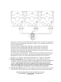
ARTESIS AMT QUICK INSTALLATION GUIDE Artesis Asset Management Toolkit
(AMT)
Before installation 1. Ensure that AMT Toolkit includes all cables (Voltage measurement cables: Fluke AC285 SureGrip™ Alligator Clips, current measurement cables, power cable, cross cable for ethernet connection), computer and its charging adapter. 2. Ensure that battery power of the computer is not low or charging cable is connected to the computer. 3. Check the Motor Control Cabinet (MCC) for installation of split‐core current transformers (CTs) which are included within AMT Toolkit. a. If it is suitable then check the motor name plate for rated current in order to use appropriate transformation ratio. b. If not, check usability of existing CTs. 4. Check the secondary output of CT which is used for measurement in order to use the appropriate Asset Management Unit (AMU). 5. Check the license status of the software to get the report of the data. Installation 1. Before setting up the AMT Toolkit, ensure that motor is not running and all switches are off. 2. Plug the power cable. 3. Connect cross cable to the computer. Current & Voltage Connections 1. Select appropriate, 1 Amp or 5 Amp, AMU for voltage and current connections. AMU for 1 Amp is provided for direct connections to the existing current transformers with 1 Amp secondary outputs of the motors with measurement units. 2. Plug voltage sockets to AMT Toolkit and connect the alligator clips to the motor terminals or other location for direct contact with the conductors. 3. Connections for Low Voltage (≤ 480V AC), Medium Voltage (> 480V AC) and Inverter Driven equipment are described. Follow the steps appropriate for the motor type. 3.1. Low Voltage Motors: For 5 Amp AMU, plug current socket to AMT Toolkit, connect current cables to multi ratio current transformers supplied with AMT Toolkit and connect multi ratio current transformers to equipment's 3 phase supply cables. Connect current cables to multi ratio current transformers as described below according to motor’s nominal current. GOSB TeknoParki Hightech Binasi Kat: 3/B 10 41480 Gebze, Kocaeli / Turkey P: +90‐262‐678‐8860 F: +90‐262‐678‐8855 [email protected] www.artesis.com Connect C1, C3, and C5 current cables to S1 terminals of CT1, CT2, and CT3, respectively. If nominal current is between 30 ‐ 100 Amps, connect C2, C4, and C6 to S2 terminals as shown in the figure above. If nominal current is between 100 ‐ 200 Amps, connect them to S3 terminals. If nominal current is between 200 ‐ 300 Amps, connect them to S4 terminals. If nominal current is between 300 ‐ 400 Amps, connect them to S5 terminals. If the MCC has existing current transformers make direct connections to those current transformers with 5 Amp secondary output. If the nominal current is between 0 – 30 Amps and current transformers do not exist at the measurement unit of the motor, use current transformers (NOT SUPPLIED) with appropriate turn ratios. Turn ratios will be selected such that current inputs are between 1.5 – 5 Amps for 5 Amp AMU and between 0.3 – 1 Amps for 1 Amp AMU. 3.2. Medium Voltage Motors: The test equipment has a limit of 480 volts for direct connection. Therefore, testing on medium to high voltage motor and driven equipment is performed by utilizing secondary circuit (low voltage) to access the currents and voltages. Lethal voltages and currents are present at the input terminals of this device. Accordingly, this unit must be used in accordance with all local and national codes for the installation and operation of low voltage electrical equipment. 3.3. Inverter Driven Motors: Make sure that voltages are measured at the output terminals of the inverter. Direct connections to the output terminals are made for low voltage GOSB TeknoParki Hightech Binasi Kat: 3/B 10 41480 Gebze, Kocaeli / Turkey P: +90‐262‐678‐8860 F: +90‐262‐678‐8855 [email protected] www.artesis.com 4.
5.
6.
7.
inverters. Voltage transformers (NOT SUPPLIED) are needed for medium voltage inverters. Turn the power switch of the AMT Toolkit and AMU unit on. Ensure that AMU’s Power led is on. Ensure that “IDLE” message appeared in the AMU’s LCD display. If the unit is not in IDLE mode, press clear button until IDLE message appears in the LCD display. Refer to section 3 in user manual for detailed information for the use of AMU unit. Configuring AES for AMT Software Configuration of AMU unit using the “set up wizard” is described below. Alternative configuration is possible from the front panel by using the buttons of the AMU unit as described in section 3 in user manual. 1. Before configuring AES Configuration Application, ensure that motor is running and voltage & current sockets are connected. 2. Select AMU model on the AES panel according to secondary amps value of current transformers (AMU 1A or AMU 5A). 3. Right click on it. 4. Select the ‘Setup Wizard’ menu item. 5. Click ‘Next’ button. 6. Enter equipment’s ‘Nominal Voltage’, ‘Nominal Current’, ‘Frequency’ and ‘Motor Speed’. 7. Choose connection type. 8. Click ‘Next’ button. 9. Enter voltage transformers’ conversion ratio (Default value is 1). If there are no voltage transformers used, leave the conversion ratio as 1. 10. Click ‘Next’ button. 11. Enter current transformers’ conversion ratio (Default value is 1). e.g. If the 100/5A is used, set the conversion ratio as 20. 12. Click ‘Next’ button. 13. Wait for 90 seconds. 14. Click physical parameters button to see the measured parameters. 15. Ensure that electrical values (currents, voltages) are same as expected and phase ordering (see section 3.4.4 in user manual for detailed information) is right. 16. Click ‘Close’ button. 17. Click ‘Next’ button. 18. Click ‘No’ button. 19. Wait for the AMU device to finish ‘Learn’ and ‘Improve’ modes, and to get into ‘Monitor’ mode. 20. Right‐click on the device and select “Waveform…” submenu. Download waveform data until ‘Save’ icon enabled and save it to a text file. Close the waveform window. 21. By clicking the ‘AMT Report’ menu, open reporting user interface. 22. If the company information was not recorded before, click on ‘Companies’ group on the left bottom on the reporting user interface or ‘Company’ menu. GOSB TeknoParki Hightech Binasi Kat: 3/B 10 41480 Gebze, Kocaeli / Turkey P: +90‐262‐678‐8860 F: +90‐262‐678‐8855 [email protected] www.artesis.com 23. Click ‘New Company’ button on the ‘Company’ ribbon bar and fill the company information on the right pane. 24. Click ‘Save’ button on the ribbon bar. 25. On the motor pane, click ‘Add New Motor’ button. 26. Fill the motor information on new motor card. 27. Click ‘Save Motors’ button. 28. A motor can be removed by clicking ‘Remove Motor’ button. 29. Motor adding, editing operations can be cancelled by clicking ‘Cancel Editing’ button. 30. Click ‘Report’ menu or ‘Reports’ group on the left bottom. The companies and their motors will be listed on the left pane. 31. Click the ‘New Report from DB’ button. The AMU devices and their data are listed on the right pane. 32. Assign waveform text file by clicking the folder icon. 33. Drag a data from that list and drop into the related company’s motor on the left so that the data can be assigned to a specific motor and a report is opened. 34. If you did not assign a waveform, you can assign it by selecting a report on the left and clicking ‘Assign Waveform File’ button. 35. A report can be viewed by double‐clicking on it. The report will appear on the right pane. 36. A report can be exported as pdf file, e‐mailed as attachment or previewed to print using the ‘Export’, ‘E‐Mail’, and ‘Preview and Print’ buttons on the ribbon bar, respectively. 37. The PSD and waveform graphs of a report can be viewed by clicking ‘PSD’ and ‘VI Waveform’ tabs, respectively. When data acquisition is done 1. Ensure that motor is not running. 2. Turn voltage, AMU, and power fuses off in order. 3. Remove current transformers. 4. Disconnect power, voltage and current cables. GOSB TeknoParki Hightech Binasi Kat: 3/B 10 41480 Gebze, Kocaeli / Turkey P: +90‐262‐678‐8860 F: +90‐262‐678‐8855 [email protected] www.artesis.com