1
VoIP 110R/200R/422R/404R/440R
User’s Guide
Trademarks
Contents are subject to revise without prior notice.
All trademarks belong to their respective owners.
FCC Warning
This equipment has been tested and found to comply with
the limits for a Class A (8xxR) or a Class B (1/2/4xxR)
digital device, pursuant to Part 15 of the FCC Rules.
These limits are designed to provide reasonable protection
against harmful interference when the equipment is
operated in a commercial environment. This equipment
generates, uses, and can radiate radio frequency energy
and, if not installed and used in accordance with the
Instruction manual, may cause harmful interference to
radio communications. Operation of this equipment in a
residential area is likely to cause radio interference in
which case the user will be required to correct the
interference at his or her own expense.
CE-mark Warning
This is a Class A (8xxR) or a Class B (1/2/4xxR) product. In
a domestic environment, this product may cause radio
interference, in which case the user may be required to
take adequate measures.
Revision
USER’S GUIDE
Part No.: 06310051011
ii
TABLE OF CONTENTS
1. ABOUT THIS GUIDE ......................................................1
1.1 Before Start up ...................................................................1
1.2 Notation Conventions (for console or telnet settings) .....2
2. START UP PREPARATION ...........................................4
3. WAN CONFIGURATION ...............................................5
3.1 Static IP Address Environment .........................................5
3.2 Dynamic IP Address Environment .................................11
3.2.1 Applying for a host name in the dynamic IP
environment ..............................................................12
3.2.2 PPPoE application set up...........................................13
3.2.3 DHCP application set up............................................18
4. LAN CONFIGURATION...............................................24
4.1 LAN Interface Configuration .........................................24
5. ADVANCED FEATURES..............................................29
5.1
5.2
5.3
5.4
5.5
5.6
Access to Advanced Features Menu ...............................29
DMZ Configuration .........................................................31
Virtual Servers Configuration ........................................34
Port Forwarding Configuration .....................................37
Special Applications Configuration ................................40
Access Control Configuration.........................................43
5.6.1 Workgroup Access Configuration.............................45
5.6.2 Packet Filter Table Configuration ............................47
5.7 Dynamic DNS Configuration ..........................................49
6. DIAL PLAN SET UP ......................................................53
6.1 Concepts............................................................................53
6.1.1 The Voice Port.............................................................53
6.1.2 The Dial Plan ..............................................................54
6.2 Web Browser Configuration ...........................................56
iii
7. CONFIGURATION EXAMPLES ...............................68
7.1
7.2
7.3
7.4
iv
The Default Dial-plans.....................................................68
ITG to ITG in the Static IP Address Environment........70
ITG to ITG in the Dynamic IP Address Environment ..75
PBX Related Issues ..........................................................78
7.4.1 CP Tone Detection ......................................................78
7.4.2 Call Security................................................................78
1.ABOUT THIS GUIDE
This Guide uses ITG-400R as a general example and contains
the following information:
Start Up Preparation: This chapter illustrates how to prepare
for the Internet Telephony Gateway (ITG) set up through
console interface or network interface.
WAN Configuration: You will learn how to set up IP address
and related configuration for your ITG-400R in the WAN side
environments such as static IP address and dynamic IP
address.
LAN Configuration: You will learn how to set up IP address
and related configuration for your ITG-400R in the LAN side
environments such as static IP address and DHCP IP address.
Advanced Features: You will learn how to set up advance
features for LAN access management and DDNS configuration
for your ITG-400R.
Dial Plan Setup: We will provide necessary procedure to guide
you step by step for a typical dial plan set up.
Configuration Example: This chapter shows you how to use
the default settings to start up your first call. Examples will be
given to show you how an ITG may be working with telephony
devices such as PBXs and phone sets.
L
Hint
Bypass the Advanced Features chapter if you do
not want to do any LAN access management.
1.1 Before Start up
Before setting up your ITG-400R the first time, you need the
following:
1
A PC that may run a web browser program such as
Netscape, Internet Explorer, etc.
A 10/100 BaseTX Cat. 5 Ethernet LAN cable with RJ-45
connector.
A console cable, where you may find it in the ITG package
(for 4/8xxR).
And later on, you are required to get familiar with your
environment, your TCP/IP network and your phone systems.
1.2 Notation Conventions (for console or telnet
settings)
This document uses the following conventions:
Examples that contain system prompts denote interactive
sessions, indicating that the user enters commands at the
prompt.
Different type styles and characters are used.
serve a variety of purposes as described below:
2
These
Convention
Description
boldface
Commands and keywords are in
boldface.
Bold Arial
User input (anything you are expected to
type in) is set in bold Arial.
italic
Arguments for which you supply values.
[ ]
Elements in square brackets are optional.
{x|y|z}
Alternative but required elements are
grouped in braces ({ }) and separated by
vertical bars ( | ).
[x|y|z]
Optional alternative keywords are
grouped in brackets ([ ]) and separated by
vertical bars ( | ).
3
“string”
A non-quoted set of characters. Do not
use quotation marks around the string or
the string will include the quotation marks.
<key>
A key on the VT-100 terminal or terminal
emulator. For example <Enter> denotes
the Enter key.
2.START UP PREPARATION
This chapter shows you how to prepare for the ITG-400R set
up for your network and/or Internet. We will focus on the web
browser usage.
Since the ITG-400R comes with two default IP addresses, one
is for LAN side that is “192.168.0.1” and the other is for WAN
side that is “172.16.0.1”. You may use any PC to connect to
the LAN port of ITG-400R, and then follow the steps below:
1) Set up the PC with an IP address in the “192.168.0.x” IP
domain, say, “192.168.0.2” with subnet mask address
“255.255.255.0” or choose “Obtain an IP address
automatically”
2) Start up the browser. In the address field, key in the
address http://192.168.0.1. The pop-up screen should
appear and prompt for user name and password. The
default values are:
User name: eitg (all lower case)
Password: 123
Now you are ready to perform the Network configuration set
up described in the next chapter.
4
3.WAN CONFIGURATION
We will show you the basic steps for a typical ITG-400R
connection in various environments. It includes static IP
address environment and dynamic IP address environment.
3.1 Static IP Address Environment
There are several typical static IP address environment where
the following procedure may apply, such as popular
broadband application with ADSL or Cable network.
Run Web Browser such as Netscape or Internet Explorer.
Set
the address field to 192.168.0.1, hit the enter key, then
ITG-400R will respond with the following page.
5
Enter eitg in “User Name” field and 123 in “Password” field,
then select “OK”, ITG-400R will show the “Main Menu” as
follows:
6
Click “NAT” for all the WAN/LAN related settings, and
ITG-400R will display the following:
7
Click “WAN” for WAN Configuration Menu, and ITG-400R will
display the following screen:
8
Click “Fixed IP” to enter all fix IP related information:
9
Fill in “IP address”, “Subnet Mask”, and “Gateway (Router) IP
address” associated with this ITG-400R.
Fill in “Primary DNS server” and/or “Secondary DNS server”
with IP address that ISP has provided.
Fill in “IP TOS” parameter for ‘Precedence’, ‘Delay’,
‘Throughput’ and ‘Reliability’ if your ISP provides. The ranges of
these parameters are:
Precedence: 0
Control(High)
to
7,
0=
Routine(Low),
Delay :0= Normal, 1= Low.
Throughput :0= Normal, 1= High
Reliability :0= Normal, 1= High
Click ‘OK’ to store all above information.
10
7=
Network
Reboot the ITG when the above information is stored
successfully.
3.2 Dynamic IP Address Environment
In this section we will show you how to obtain a valid host
name in the dynamic IP address environment first, followed by
the way to set up a typical ITG-400R connection in the
dynamic IP address environment via built-in PPPoE, DHCP,
and DDNS clients.
11
3.2.1 Applying for a host name in the dynamic IP
environment
First, it is required to apply for a DDNS host name from
http://www.dyndns.org for the ITG. (For example, the name
you may obtain is mary01.dyndns.org for the ITG.)
mary01.dyndns.org is applied for the ITG.
If you have already obtained a valid host name with your user
name and password from the dynamic DNS server such as
www.dyndns.org, you may skip the following and go to
Section 3.2.2 directly.
1) Go to the dyndns web page
www.dyndns.org
2) Click “Sign Up Now”
3) Click “Agree” on Acceptable User Policy.
4) Create NIC User Account
Example:
User Name: Mary
Email Address: [email protected]
Password: hbear
Click “Create Account”
5) Wait for DYNDNS email for confirmation of your account.
6) Go to the www.dyndns.org web page again
7) Click “login”
8) Type in your user name and password
9) Click “Dynamic DNS” and “Add New Host”
10) Type in ‘New Host Name’ and select ‘dyndns.org’
For example: mary01.dyndns.org
12
11) Click “Add Host” if another host name is needed and go to
Step 10, otherwise the host name application is done.
L
Hint
Please refers to Chapter 5.7 for details related to
the DDNS configuration.
3.2.2 PPPoE application set up
In this section we’d like to introduce steps to setup the PPPoE
application for dynamic IP address environment.
Use Browser to get into the “Main Menu”:
13
Click “NAT” for all the WAN/LAN related settings, and
ITG-400R will display as follows:
14
Click “WAN” for WAN Configuration Menu, and ITG-400R will
display the following screen:
15
Click “PPPoE” and prepare to key in all PPPoE related
information:
16
Select “ON” for PPPoE, key in “User name” and “Password”
that ISP has provided. “Service name” may be entered if your
ISP has also provided it.
Click “OK” to store all the above information.
17
Reboot the ITG when all the above settings are stored
successfully.
3.2.3 DHCP application set up
In this section we’d like to show you how to configure the DHCP
Client application for dynamic IP address environment.
Use Browser to get into the “Main Menu”:
18
Click “NAT” for all the WAN/LAN related settings, and
ITG-400R will display the following screen:
19
Click “WAN” for WAN Configuration Menu, and ITG-400R will
display the following screen:
20
Click “DHCP Client” for DHCP Client Settings, and ITG-400R
will display the following screen:
21
At “DHCP Client” field, select “on” for enable DHCP client.
Key in “Router name” and “Domain name” if ISP requires.
At “Use local MAC addr.” field, select “Yes”, if ISP requires
Local MAC addr. for link authentication, and fill in the following
“Local MAC addr. field ” with your Local MAC address.
Click “OK” to store all the above information.
22
Reboot the ITG when all the above settings are stored
successfully.
23
4.LAN CONFIGURATION
We will show you the basic steps to configure a typical
ITG-400R in the LAN environment.
4.1 LAN Interface Configuration
Run Web Browser such as Netscape or Internet Explorer.
Set
the address field to 192.168.0.1 then hit the enter key.
ITG-400R will respond with the following page.
Enter eitg in “User Name” field and 123 in “Password” field.
Then select “OK”. ITG-400R will show the “Main Menu” as
24
follows.
Click “NAT” for all the WAN/LAN related settings, and
ITG-400R will display the following screen:
25
Click “LAN” for LAN Configuration Menu
26
Specify the LAN Port IP Address, and Subnet Mask.
About DHCP Server setting, you can specify the number of
DHCP clients, the range is ‘1’ to ‘253’ and ‘0’ will disable DHCP
Server.
Fill in the “Client start address” to specify the start IP address if
DHCP Server is enable.
Click “Save The Changes” to save all input information.
27
Reboot the system if all the above settings are saved.
28
5.ADVANCED FEATURES
This chapter shows you the advanced features offered by
ITG-400R and helps you to configure your ITG step-by-step for
LAN access management.
5.1 Access to Advanced Features Menu
Use Browser to get into the “Main Menu”:
Click “NAT” for all the WAN/LAN related settings, and
ITG-400R will display the following screen:
29
Click “Advanced Features” for the Advance Features Menu,
and start the Advanced Features settings.
30
5.2 DMZ Configuration
This option allows one computer on your LAN to be exposed to
all users on the Internet.
Get into “Advanced Features”
Click “DMZ” and prepare to key in all related information:
31
Switch “DMZ” field to ‘on’.
Enter the destination device’s IP address in “NAT DMZ host”
field.
Click “OK” to store all above data.
32
Reboot the system to make these changes effective.
33
5.3 Virtual Servers Configuration
This option allows servers on your LAN to be accessible by
Internet users. The NAT router redirects the external port to the
internal port.
If a web server 192.168.0.20 (port number 80) is behind the
NAT router, and could be accessed by Internet users via TCP
port 8080, the following steps should be taken:
Get into “Advanced Features”
Click “Virtual Servers” and prepare to key in all related
information:
34
Enter 8080 in “External Port #” field.
Enter 192.168.0.20 in “Internal IP” field.
Enter 80 “Internal Port #” field.
Choose the TCP in “Protocol” field.
Tick the “Active” field to enable Virtual Server function.
Click “OK” to store all above data.
35
Reboot the system to make these changes effective.
36
5.4 Port Forwarding Configuration
This option also allows servers on your LAN to be accessible by
Internet users. The NAT router directly forwards the external
ports to the internal ports.
If a server 192.168.0.30 (port 1040 to port 1060) is behind a
NAT router, and could be accessed by Internet users via TCP
port 1040 to port 1060, the following steps should be taken:
Get into “Advanced Features”
Click “Port Forwarding” and prepare to key in all related
information:
37
Enter 192.168.0.30 in “Internal IP” field.
Enter 1040 in “Port number from” field.
Enter 1060 in “Port number to” field.
Choose TCP in “Protocol” field.
Tick “enable” field to enable Port Forwarding function.
Click “OK” to store all above data.
38
Reboot the system to make these changes effective.
39
5.5 Special Applications Configuration
This option allows certain Internet applications, which use
non-standard TCP/UDP ports to pass through the NAT router.
If a PC 192.168.0.20 is behind the NAT router, it will use TCP
port 1400 to port 1404 as source port to access an Internet
server, and the Internet server will respond to the PC with UDP
packets of port number 1300 as destination port, then the
following steps should be taken:
Get into “Advanced Features”
Click “Special Applications” and prepare to key in all related
information:
40
Enter 1300 in “In Port no. from” field.
Enter 1300 in “In Port no. to” field.
Choose UDP in “In Protocol” field.
Enter 1400 in “Out Port no. from” field.
Enter 1404 in “Out Port no. to” field.
Choose TCP in “Out Protocol” field.
Enter the description in “Description” field.
Tick the “Active” field to enable this special App. setup.
Click “OK” to store all above data.
41
Reboot the system to make these changes effective.
42
5.6 Access Control Configuration
This option allows you to cluster hosts in LAN into groups and
to define WAN access policy for each LAN group.
Each Workgroup has its own packet filter table, which specifies
how to block the PC or LAN devices.
For example a PC 192.168.0.10 belongs to Workgroup 1, and
Workgroup 1 is not allowed to access any HTTP server in the
Internet, then the following steps should be taken:
Get into “Advanced Features”
Click “Access Control” for Access Control menu.
43
Use Workgroup and Packet Filter Table settings to control the
user’s access authority.
44
5.6.1 Workgroup Access Configuration
This option allows you to cluster hosts in the LAN into
workgroups; each workgroup is associated with a unique
packet filter table.
Click “Workgroup” and prepare to define the workgroup.
45
Enter 1 in “Select a Workgroup number” field.
Enter Operation in “Description”
Choose ”add” and “IP” in “addr type” field
Enter 192.168.0.10 “Address” field.
Click “OK” to store all above data.
46
5.6.2 Packet Filter Table Configuration
This option allows you to define packet filter policies for each
workgroup.
Click “Packet Filter Table” and prepare to key in all related
information:
47
Enter 1 in “Select a Workgroup number” field.
Choose ”add” and “TCP” that you want to block.
Enter the starting block port number 80 in “Port range from”
field.
Enter the ending block port number 80 in “Port range to” field.
Click “OK” to store all above data.
A list for the packet filter setting result will be displayed.
Packet filter table 0 is the default filter table, if a PC is not
belong to any packet filter table, then the policy of packet filter
table 0 will be applied to this PC.
48
5.7 Dynamic DNS Configuration
The Dynamic Domain Name Server allows Internet Users to
connect to your Virtual Servers using a URL rather an IP
address.
Get into “Advanced Features”
Click “Dynamic DNS” and prepare to key in all DDNS related
information:
49
Choose “ON” for enable DDNS in Dyn-DNS field.
Key in “Server Name”, “Host Name”, “User Name”, and “User
Password” provided by your Dynamic DNS service provider.
Click “OK” to store all the above information.
50
Click “Store” to store information in the Flash memory.
51
Reboot the ITG when all the above settings are stored
successfully.
52
6.DIAL PLAN SET UP
This chapter shows you the basic concept and steps to help
you configure your ITG through the LAN port. It includes the
ITG-400R voice port and Dial Plan.
6.1 Concepts
6.1.1 The Voice Port
There are two types of voice port, FXO (Foreign eXchange
Office) and FXS (Foreign eXchange Station). You should locate
them at the labels of the RJ-11 ports.
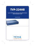
FXO port
The FXO port allows connecting to a device which is
associated with a phone number and which can generate a ring
signal; say 316, or 408-1234. So the only connection for FXO
port will be to your local PSTN Line or one of the analog
extension line associated with your PBX system.
FXO
316
408 -1234
PSTN
When
your
FXO
port
connects to a PSTN Line, the
VoIP call can be made to the
local number (408-1234). Or,
vise versa you may make a
VoIP call through the phone
number 408-1234.
The same is applied to a PBX system. You are required to know
which extension number will be assigned to the FXO port. Your
PBX users will need to know this number to make a VoIP call.
53
L
Hint
The FXO port cannot connect to a device such as
telephone or fax machine since they do not provide
any phone number / extension and cannot
generate any ring signal. If you connect those to the
FXO port, you may hear nothing once you pick up
the handset.
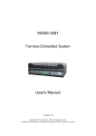
FXS port
The FXS port allows the connection to a device such as
telephone, fax machine, or trunk line of a PBX system (For
4-port and 8-port model only).
FXS
316
203
The FXS port is like your local
phone service provider that
can generate and provide ring
signal. It is easy to tell if you
have connected a device to
the FXS port and you may hear
the dial tone provided by the
FXS port once the handset is
off-hook.
The FXS port is with voltage and current. DO NOT
connect the port to any PBX extension line or
Warning PSTN line. This may result in the FXS port or your
PBX extension port malfunction.
6.1.2 The Dial Plan
Before you start setting up the dial plan for the ITG, it is required
to know the following basic concept associated with the ITG.
Phone number
Hunt Group ID
Destination ID
54
Destination
1) Phone Number
The “Phone number” associated with the ITG is a set of
digits. You may look at that as an area code associated with
your phone number. This number will only map to one Hunt
Group in this example. You may reference to Section 7 for
more details regarding configuration and Dial Plan
examples.
Hunt Group
Number
One
To
One
‘10’
‘408’
2) Hunt Group ID
The “Hunt Group ID” here is an interpreter between phone
number and Destination ID. The ITG phone table will be
based on the number you dial to find the related hunt group.
So, different numbers may map to the same hunt group. A
Hunt group consists of at least one Destination ID. It means
that when a call is placed the first available Line Destination
ID will be connected.
Destination ID
Hunt Group
One
‘10’
L
Hint
One
‘10’
In this guide, we will only set up one Hunt Group to
one Destination.
This will be convenient for you to trace the
relations.
3) Destination ID and Destination
55
To
The “Destination ID” here is an interpreter between Hunt
Group and physical Destination. Hunt Groups may map to
the same destination ID.
The destination is either a local physical port or a remote IP
address that ITG should make a call to. Each Destination ID
maps to a physical destination. There are two types of
physical destination.
A physical port on the ITG, i.e. the FXO/FXS port
A H.323 VoIP gateway with a fixed IP address or a host
name.
Destination
Destination ID
One
L
Hint
To
One
‘1’
‘0’
‘10’
‘mary01.dyndns.org’
In this guide, we will use a dial plan table as below for
illustration purpose.
Number
Hunt Group
Dest. ID
Destination
201
1
1
0
408
10
10
mary01.dyndns.org
‘201’ is a default number, ‘408’ is a new number we
will add onto the table.
6.2 Web Browser Configuration
Use Browser to get into the “Main Menu” as follows, the default
IP address of ITG-400R is 192.168.0.1.
56
Click “VOIP” for all the telephony related settings, and
ITG-400R will display as follows:
57
You are advised to set up your Dial Plan associated with the
ITG first before dialing any number and making a VoIP phone
call. Click ”Dial Plan”, it will display as follows:
58
Click “Phone/Hunt Group/Destination Settings” and prepare to
enter phone numbers, and ITG-400R prompts the following:
59
Choose “Add”, “Telephone”, and “Select”, and ITG-400R will
display the following screen:
60
Fill in the information associated with “Telephone Number”,
“Hunt Group ID”, “Min. Digits”, “Max Digits”, and “Strip Length”.
Make sure the above data is correct then click “Complete”.
Telephone Number – A set of digits. You may look at that as an
area code associated with the remote Gateway.
Hunt Group ID – An interpreter between Telephone Number
and Destination ID.
Min. Digits – The minimum number of digits need to dial for
remote Gateway, usually is the number of digits of Telephone
number above.
Max. Digits –The maximum number of digits need to dial for
remote Gateway. The difference of “Max. Digits” and “Min.
Digits” is the total phone numbers that you can assign to the
remote Gateway.
61
Strip Length – The number of digits needed to be strip off from
the beginning of the dialing digits.
Append prefix – The digits needed to be appended in front of
the dialing digits after it is stripped for the strip length.
The newly added telephone number will be displayed for
confirmation as follows:
Choose “Add” and “Hunt Group” then click “Select”, and
prepare to add Hunt Group ID. The ITG-400R will show the
following:
62
Enter the information related to “Hunt Group ID” and
“Destination ID”, then click “Complete”. The newly added Hunt
Group ID and Destination ID will be displayed for confirmation
as follows.
63
Hunt Group ID – An interpreter between a Hunt Group and a
Destination.
Destination ID – The destination is either a physical port or a
remote IP address that ITG should make a call to. Each
Destination ID maps to a physical destination. There are two
types of physical destination.
A physical port on the ITG, i.e. the FXO/FXS port
A H.323 VoIP gateway with a fixed IP address or a host
name.
64
Now choose “Add” and “Remote_Destination_IP” for setting up
the Destination IP address. Click “Select”, and the ITG-400R
prompts as follows:
65
The information associated with “Destination ID” and “IP
Address” of the remote Gateway should be filled in. Click
“Complete”. The newly added remote IP address will be
displayed for confirmation as follows:
66
Now you may test the phone connected to the remote Gateway
(211.20.86.4) with phone number “88635xxx” from your local
phone.
67
7.CONFIGURATION EXAMPLES
7.1 The Default Dial-plans
Before any configuration set up, your ITG should have the
following basic default information.
Network:
IP
: 192.168.0.1
Mask:
: 255.255.255.0
Gateway : 0.0.0.0
Dial Plan:
No.
Hunt Dest. Dest.
Group ID
201
1
1
0 (local port #1)
202
2
2
1 (local port #2)
203
3
3
2
204
4
4
3
20X
X
X
(X-1)
(X is from 1 to 8, and it varies depending on your ITG model)
FXS
202
201
L
Hint
68
Suppose two telephones are
connected to two of your ITG
FXS ports, say port 1 and port
2 respectively, you just pick
up phone 1 and dial ‘202’
directly, phone 2 should ring.
202
ITG
local port
)))
#2
You may also check the LED indicators on the ITG.
When it rings, the related LED should flash. After
you pick up the handset, it should remain on and off
when the phone is on hook.
Now let’s test your ITG that is equipped with FXO interface.
Assume you have one extension line associated with your
PBX system, say, 316 as the designated extension number,
we connect this line to ITG port 1 (FXO port), then connect a
telephone phone set to ITG port 3 for example.
FXS FXO
203
316
100
Pick up your extension handset, for example, 100 and dial
‘316’. After two rings, you should hear a dial tone. Now dial
‘203’ the telephone connected to the ITG FXS port should
ring.
L
Hint
69
If you do not hear the dial tone, please check the
line impedance of your PBX. You should find a
Guide for setting the appropriate line impedance in
your package if your ITG is equipped with FXO
port. Please set it up accordingly to adjust your
FXO port.
Now let’s make a call to your extension. Pick up the handset
connected to the FXS port and dial ‘201’, you should hear a dial
tone (This means that ITG picks up the line connected to your
PBX). Then dial ‘100’, your extension handset should ring right
away.
L
Hint
This guide only uses the default values. Once you
are familiar with the dial plan set up, you may
design your own. You may set it up with only one
digit if you wish, say ‘1’, and ‘100’ rings.
7.2 ITG to ITG in the Static IP Address
Environment
The previous section shows you how to test your ITG without
modifying any settings. This section will show you how to
connect two ITGs together and make VoIP calls.
Assume that we have another ITG, say ITG B, with the default
settings as well. Now, let’s set up the IP address of ITG B to,
e.g. ‘192.168.0.2’ and connect it to ITG A with the following
three steps.
Step 1.
ITG B:
Configure the WAN IP (Please refer to Chapter 3.1.)
Step2.
Connect ITG A and ITG B to the same Ethernet switch or
hub.
Step3.
ITG A:
Ping ITG B
Ping (192.168.0.2) 56 data byte
192.168.0.2 is alive
70
ITG B:
Ping ITG A
Ping (192.168.0.1) 56 data byte
192.168.0.1 is alive
After these three steps, both ITGs should find each other on the
same network.
Now let’s set up the remote H.323 gateway for this two ITGs.
ITG A:
Refer the following dial plan information to configure ITG
A dial plan (Please refer to Chapter 6.2.)
ITG B:
Refer the following dial plan information to configure ITG
B dial plan (Please refer to Chapter 6.2.)
The dial plan associated with these two ITGs should have the
following new record after the above commands.
ITG A:
No.
02
Hunt Group Dest. ID
10
10
Dest.
192.168.0.2
Hunt Group Dest. ID
10
10
Dest.
192.168.0.1
ITG B:
No.
01
Now, once ITG A gets a dialed number “02” it will direct the call
to ITG B. The same is true for ITG B. The dialed number ‘01’ will
be mapped to ITG A accordingly.
71
Assume both ITGs have a FXS port corresponding to port#3
ITG A (01)
203
ITG B (02)
203
each with a phone set connected to it.
ITG A:
Pick up handset and dial “02203”, where ‘02’ points to ITG B
and ‘203’ for port 3 of ITG B. The phone attached to ITG B
should ring.
ITG B:
Pick up the handset and dial “01203”, where ‘01’ points to ITG A
and ‘203’ for port 3 of ITG A. The phone attached to ITG A
should ring.
L
Hint
L
Hint
72
In this example, we assign each ITG with an unique
number. You may treat that number as an area
code. Each ITG represents a different area.
ITG A is with area code 01 and ITG B is 02. So If
you have more, you may assign to other ITGs with,
03, 04, etc.
If you can not hear the ring signal, please do make
sure of the following:
1) Both ITGs can ping each other
2) Phone sets are connected to the correct ports.
In this example, it should be the FXS port. Also
the phone number will be “20X” where X
corresponds to the location of the port.
3) Make sure you’ve stripped the number as
specified in the command “atpm aadd”
correctly.
4) The LED associate with the phone line should
turn on(pick up the phone) or flash(ringing).
We may continue to use the configuration mentioned in Section
7.1 for PBX connections.
ITG A
203
ITG B
203
201
316
100
ITG A:
The user at ext. 100 wants to make a call to ITG B, 203. What
we need to do is to pick up the handset with extension ‘100’
and dial ‘316’. After you hear the dial tone again, dial ’02-203’.
Then, the phone attached to ITG B should ring.
ITG B:
73
If users at ITG B want to make a call to ext 100 through ITG A,
one should dial, ’01-201’ where the PBX line is connected to
port 1. After hearing the dial tone, just dial the extension
number ‘100’.
L
Hint
Imagine how we use the PBX with associated
extension handsets. We pick up the handset and
dial any extension number directly to your
colleagues, and dial ‘0’ or ‘9’ to make a call to PSTN
network.
The same is with ITG B, after you dial “01-201”, you
can do the same thing because “01201” connects
you to the extension handset 316. In this scenario
the handset with extension 203 connected to ITG B
may also be looked as an extension of the PBX.
After all of the above, your ITG should perform normally. Let’s
do the following two things:
A) Modify the IP address, Mask, and Gateway to your network
so that the ITG may connect to the Internet. Do the same
thing to your second, and third ITG so they may connect to
the Internet as well.
B) Check the bandwidth, and the router. Normally, if you can
ping each other, it means that they should talk to each other
via VoIP calls.
The average bandwidth for each channel is from
12kbps to 16kbps by default. In a heavy traffic
Warning network, the available bandwidth between two
nodes may affect the voice quality.
74
7.3 ITG to ITG in the Dynamic IP Address
Environment
The previous section shows the steps regarding how to set up a
typical ITG-to-ITG connection in the static IP address
environment without modifying any settings. This section we
will show you how to connect two ITGs in a dynamic IP address
environment via built-in PPPoE, DHCP, and DDNS clients.
Assume there is another ITG, say ITG B, located at Site B with
default settings. First of all, it is required to apply for a DDNS
host name from http://www.dyndns.org for ITGs at Site A and
Site B. (Please refer Chapter 3.2.1 Applying for a host name in
the dynamic IP environment).
For example, the names are mary01.dyndns.org for ITG at Site
A, and mary02.dyndns.org for ITG at Site B.
mary01.dyndns.org is applied for ITG at Site A,
mary02.dyndns.org is applied for ITG at Site B.
Other parameters associated with this topology are:
ITG at Site A has PPPoE, and DDNS clients enabled
ITG at Site B has DHCP, and DDNS clients enabled.
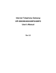
The dial plan and network topology can be shown as follows:
Site A:
No.
408
Hunt Group Dest. ID
10
10
Dest.
mary02.dyndns.org
Hunt Group Dest. ID
10
10
Dest.
mary01.dyndns.org
Site B:
No.
886
75
PPPoE
DHCP
Internet
DDNS
ADSL Modem
Area code
886
Cable Modem
Area code
408
886
Mary01.dyndns.org
61.59.73.172
#201
408
A
Mary02.dyndns.org
210.20.96.2
B
#203
ITG configuration (ADSL PPPoE connection) at Site A:
PPPoE section:
Refer the PPPoE application set up procedure to configure
Site A dynamic connection (Please refer to Chapter 3.2.2.)
DDNS client section:
Refer the Dynamic DNS configuration procedure to
configure Site A dynamic dns (Please refer to Chapter 5.7.)
76
Dial plan settings:
Refer the dial plan configuration to configure Site A dial plan
(Please refer to Chapter 6.2.)
ITG configuration (cable connection) at Site B:
DHCP section:
Refer the DHCP application set up procedure to configure
Site B DHCP connection (Please refer to Chapter 3.2.3.)
DNS server section:
Refer Chapter 3.1 page 9, WAN IP set up section to
configure Site B DNS server.
DDNS client section
Refer the Dynamic DNS configuration procedure to
configure Site B dynamic dns (Please refer to Chapter 5.7.)
Dial plan section:
Refer the dial plan configuration to configure Site B dial plan
(Please refer to Chapter 6.2.)
After these modifications, users at Site A are able to dial “408 +
telephone number” to call users at Site B and conduct VoIP
voice conversation. Users at Site B are able to perform VoIP
voice communication by dialing number “886 + telephone
number” toward users at Site A. (Please note that there is a
Max. digits (8) limitation of dial string in this case. Users may
modify this parameter to meet different needs.)
Warning
77
If calls can not be made, please check:
a. Connectivity between ITGs is valid. (This may
be checked via ping command in ITG.)
b. DDNS name is correctly updated.
7.4 PBX related issues
There are some issues related to PBX system. There are: 1)
CP (Call Progress) Tone detection, and 2) Call Security.
7.4.1 CP Tone Detection
You may encounter a problem when your call goes to PBX via
a VoIP connection, such as the caller may already hang up
the phone but the PBX port is still active.
The cause of this problem may be due to the CP tone
mismatch. The ITG cannot understand the Tone from PBX. So
it still considers the line is on and never hangs up.
Once this has happened, you may find a technical document
provided by your vendor that contains the corresponding
information and guides you to fix this problem.
7.4.2 Call Security
The ITG is a standard H.323 VoIP gateway that will allow any
standard H.323 device to make a VoIP connection to it. That
means no matter where you are, once you have a H.323
device such as another ITG, or a software package like
Microsoft NetMeeting, you may make a VoIP call to this ITG
any time once it connects to the Internet.
If the ITG is only equipped with FXS port, then it should be
very little concerns regarding the unauthorized use of the
VoIP link. But once it is connected with either a PBX or PSTN
line, you may be opening a phone line for any Internet users to
make an unauthorized phone call. For example, one may
make an International call from Hong Kong to Europe through
your ITG located in Singapore.
78
To prevent this from happening, you are advised to do the
following:
1) Restrict the right to use associated with the line. For
example, if the line goes to an extension number
associated with a PBX, ask the PBX manager to restrict
this line from dialing to certain numbers. Or ask the PSTN
service provider to limit the line usage as well.
2) Re-check the dial table. Check the dial plan table that
only allows certain numbers may make calls. That is,
remove the unnecessary numbers and restrict the
maximum digit or prefix the allowed number inside ITG so
the unauthorized phone call may not be made through the
ITG.
79
80