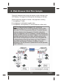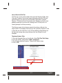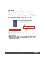
1
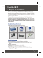
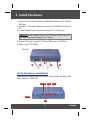
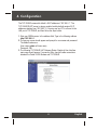
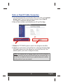
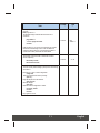
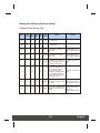
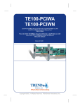
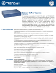
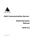
TVP-224HR
4-port VoIP Gateway with 4-port Broadband Router
Quick Installation Guide
Version 07.25.05
TRENDnet
TRENDware, USA
What's Next in Networking
Copyright ©2005. All Rights Reserved. TRENDware International, Inc.
Table of Contents
English ......................................................................................................
1. Prepare for Installation ......................................................................
2. Install Hardware ................................................................................
3. Configure the computer's TCP/IP Settings ........................................
4. Configuration .....................................................................................
5. Connection through Telnet .................................................................
6. Connection through Console .............................................................
7. Dynamic DNS (Domain Name Server) ..............................................
8. Web Browser Dial Plan Sample .........................................................
1
1
2
3
4
9
10
12
14
English QIG
1. Prepare for Installation
Thank you for purchasing the TVP-224HR. This VoIP Gateway Router will
allow you to share your broadband Internet connection with wired 10/100Mbps
Fast Ethernet computers as well as integrate your existing analog / PBX phone
system for Internet telephone.
This guide will help you setup and configure your VoIP Gateway Router.
Following the installation instructions should be quick and easy. If you run into
problems, please refer to the detailed installation procedures on the CD User's
Guide. If you need further technical support, please visit www.TRENDNET.com
or call by phone.
Verify Package Contents
Please make sure you have everything in the box:
TVP-224HR
4-port VoIP Gateway with 4-port Broadband Router
Quick Installation Guide
Version 07.25.05
TRENDnet
TRENDware, USA
What's Next in Networking
Copyright ©2005. All Rights Reserved. TRENDware International, Inc.
TVP-224HR
CD-ROM
Quick Installation Guide
AC Power Adapter
RJ45 Ethernet (LAN) Cable
RS-232 Console Cable
Verify Equipment
Before installing the VoIP Gateway Router you should have:
1. A working DSL Internet connection with Static IP or Dynamic IP with
DDNS.
2. Cable / DSL Modem
3. A computer with wired network card installed.
4. TCP/IP protocol installed on each wired computer.
5. A Web Browser such as Internet Explorer (5.0 or higher) or Netscape
Navigator (4.7 or higher).
1
English
2. Install Hardware
1. Connect a RJ-45 network cable from Cable/ADSL Modem to TVP-224HR's
WAN port.
2. Connect a RJ-45 network cable from one of the TVP-224HR's LAN ports to
PC.
3. Connect Analog Phones/ Fax machine using RJ11 to FXS port(s).
WARNING: Never connect a Trunk Line / PSTN line to a FXS Port. This
will result In permanent damage to the FXS port.
4. Connect FXO port(s) using RJ 11 Cable to PBX system or PSTN line.
5. Power on your TVP-224HR.
TVP-224HR
2
1
4
5
3
Verify Hardware Installation
Make sure the following Router LEDs are on: Power, System (blinking), WAN,
LAN (100Mb/s or 10Mb/s Off)
SYSTEM LAN
LINE
POWER
WAN
2
English
3. Configure the computer's TCP/IP Settings
To verify that your computer can communicate with your VoIP Gateway Router,
you need to configure the TCP/IP settings in your PC Operating System (OS).
Set up the PC to “Obtain an IP address automatically”. Detailed setup
procedures for Windows OS computers can be found in the User Manual on
the CD provided. If you are running any other OS please see your system
documentation for configuration information.
3
English
4. Configuration
The TVP-224HR comes with default LAN IP addresses “192.168.0.1”. The
TVP-224HR DHCP server is always enabled, and by default assigns 30 IP
addresses starting from 192.168.0.10. You may use any PC to connect to the
LAN port of TVP-224HR, and then follow the steps below:
1. Start your WEB browser. In the address field, Type in the following address
http://192.168.0.1.
2. The pop-up screen should appear and prompt for user name and password.
The default values are:
User name: admin (all lower case)
Password: 123
3. The following TVP-224HR VoIP Gateway Router Graphical User Interface
main page should appear. If connection fails, check all cable connections
between the Cable / ADSL Modem and TVP-224HR.
4
English
Internet Access
The following set-up information is designed to help you set-up your gateway to
connect to the Internet. The set-up is different depending upon the type of
Internet Connection you have with your ISP (Fixed IP, PPPoE or DHCP). If
you're not sure what type of connection you have, please contact your Internet
Service Provider and collect the required information. Below is a table that
outlines the basic data you will require from your ISP.
Connection Type
Data required
Fixed IP (Static)
Fixed IP Address, Subnet Mask, Default
Gateway and Primary DNS (Secondary
DNS is optional).
PPPoE
Login name and password (Service Name
is optional)
DHCP
Usually, none. But some ISP may require a
particular Hostname, Domain name, or MAC
(physical) address.
After setting up Internet Access you will be able to Remote Manage the
Gateway using the WAN IP. By default the Web Access and Telnet
Access management are enabled. Both of these methods provide
access over the internet so they do pose a potential security risk. It is
recommended that once configuration is complete, both Web and Telnet
access are disabled for security reasons. Turning of Web Access
disables access from the Internet; however, you will still have web
browser access from the LAN side from a computer in the same
segment. If you prefer leaving Web and / or Telnet access enabled, be
sure to change the administration password. In the event that you
should forget the password see section 6 Connection through Console.
5
English
Static or Fixed IP Cable Connection
1. From the Navigation Bar on the left side of the screen, Click on the Internet
Access Option. From the Internet Access sub-menu, Select Fixed IP.
The Fixed IP Configuration page will appear.
2. Enter all field information as provided by your ISP and Click Save.
3. Reboot the TVP-224HR system in order for the changes to take effect.
4. Launch your web browser, (Internet Explorer or Netscape Navigator) Type
http://www.trendnet.com in the address bar, and hit the Enter key. If the
website appears, your router is configured correctly.
NOTE: If the website does not appear, please verify that the information
is entered correctly. Also call your ISP and verify your connection type. If
you still can not establish Internet Access, please reference the trouble
shooting section of your user manual.
6
English
PPPoE DSL Connection
1. Click on the Internet Access option on the left-hand side of the screen and
Select PPPoE. The WAN PPPoE configuration page will appear.
2. Enter PPPoE User Name and Password as provided by your ISP.
3. Click Save.
4. Reboot the TVP-224HR system in order for the changes to take effect.
5. Launch your web browser, (Internet Explorer or Netscape Navigator) Type
http://www.trendnet.com in the address bar, and hit the Enter key. If the
website appears, your router is configured correctly.
NOTE: If the website does not appear, please verify that the information
is entered correctly. Also call your ISP and verify your connection type. If
you still can not establish Internet Access, please reference the trouble
shooting section of your user manual.
6. Setup DDNS Client (See section 7 on DDNS Client).
7
English
DHCP Connection
1. Click on the Internet Access option on the left-hand side of the screen and
Select DHCP. The WAN PPPoE configuration page will appear.
2. Enable DHCP, and enter Hostname, Domain Name and / or WAN MAC
Address (To find the WAN MAC Address, please navigate to Home / System
Status page) if required by your ISP.
3. Click Save.
4. Reboot the TVP-221H system in order for the changes to take effect.
5. Launch your web Browser, (Internet Explorer or Netscape Navigator) Type
http://www.trendnet.com in the address bar, and hit the Enter key. If the
website appears, your router is configured correctly.
6. Setup DDNS Client (See section 7 on DDNS Client).
NOTE: This quick guide covers only the most common situations.
Please refer to the User Guide (CD) for more information. For console /
telnet configuration, please reference the Advanced User Guide (CD) for
more detailed information.
8
English
5. Connection through Telnet
To use Telnet, Internet Access must have been previously setup so that the
gateway is visible on the internet (See User Guide for More Information).
Alternatively, you can use Telnet to locally access the TVP-224HR, if you are
under a router or switch and the TVP-224HR and your computer are in the
same network segment.
To access the TVP-224HR Gateway from a remote location using Telnet,
perform the following tasks:
Prompt
Type
Open the windows command prompt and enter the telnet
command followed by the IP address of the TVP-224HR
Gateway you want to access.
None
telnet
xxx.xxx.xxx
When the TVP-224HR Gateway prompts you to Login, enter
the user name "admin”
Login:
admin
When the TVP-224HR Gateway prompts you for Password,
enter the password. “Console>” will appear. The default
password is "123" but it is recommended that the password be
changed for security considerations. The password can be
changed from the Web Browser Administration / Password
submenu page.
Password:
123
Console>
ping
xxx.xxx.xxx
Task
Type in “ping xxx.xxx.xxx”, where xxx.xxx.xxx is your ISP
provided DNS Server IP or any known Public Internet Address.
The following dialogue confirms Internet Access
Console>ping 168.95.1.1
ping <168.95.1.1>: 56 data bytes
168.95.1.1 is alive
If the ping times out, you do not have Internet Access or the
Public IP Address you pinged is incorrect. Try another IP
Address. If you confirm that you do not have Internet Access,
please refer to the trouble shooting section of the User Manual
or consult your ISP to make sure your Internet Access Data is
correct and accurately entered into the TVP-224HR.
9
English
6. Connection through Console
The console port uses a DB-9 RS-232 connector. The supplied straight through
RS-232 cable connects the console port of the TVP-224HR to a console PC or
terminal.
Task
Prompt
Type
Baud rate
Number of data bit
Parity check
Number of stop bit
Flow control
19,200
8
None
1
None
Connect RS-232 Cable to TVP-224HR RS-232 console port a
your computer that you will use as a configuring terminal
Open HyperTerminal and enter the following Input Parameters
when prompted:
When HyperTerminal Screen appears type “123”
123
In the event that you forget your administration password, you
can gain console access to the TVP-224HR using the super
password. The super password is the last six digits of your MAC
address located on the bottom of your TVP (00-50-2d-xx-xx-xx).
At the Console prompt enter the super password without
hyphens. The password is all lower case. After gaining access,
at the console prompt type in
net set manager password
<new_password> <new_password>
net store
net reset
If entry of new password is successful, the console will list “OK”.
You will now be able to gain Web Access from a PC in the same
local segment using the TVP-224HR LAN IP Address. If Web
and / or Telnet Access are enabled, you will also be able to
remote access the TVP-224HR by entering http:// followed by
the TVP-224HR WAN IP or domain name.
10
English
Task
Prompt
Type
Console>
ping
168.95.1.1
Console>
on / off
At the prompt
Console>
Enter ping 168.95.1.1
The following dialogue indicates that Internet Access is
successful.
ping 168.95.1.1
1 out of 1 pings succeeded.
Console>
If the ping times out, you do not have Internet Access. Please
refer to the trouble shooting section of the User Manual or
consult your ISP to make sure your Internet Access Data is
correct and accurately entered into the TVP-224HR.
The following commands enable / disable web and telnet
access respectively.
Net set http <on/off>
Net set telnet <on/off>
To reset to Factory Default settings, please perform the following
commands to:
Erase all 'port', 'codec' & 'h323' configuration
config erase
Then access dial plan edit mode by entering
atpm req
Purge the dial plan from the database
atpm purge all
Store the changes
atpm store
Reset the network configuration to default
net set fac_default
net store
net reset
Key in "yes" to re-boot.
11
English
7. Dynamic DNS (Domain Name Server)
This free service is a very useful feature. It allows Internet users to connect to
the TVP-224HR using a URL, rather than an IP Address. This also solves the
problem of having a dynamic IP address. With a dynamic IP address, your IP
address may change whenever you connect to the Internet, making it difficult
for others to find / connect to the TVP-224HR. With Internet DDNS, your IP
may change but your Domain Name is Static.
The Service works as follows:
1. You must register for the service at www.dyndns.org using the dyndns.org
domain. This is the only Dynamic DNS service currently supported.
2. After registration, follow the Service Provider's procedure to request a
Domain Name, and have it allocated to you.
Select Internet on the main menu, then DDNS submenu, to see a screen like
the following:
12
English
3. Enable Dyn-DNS. Please be sure to enter the data correctly. For instance, if
you registered johnsmith.dyndns.org, please make sure that “dyndns.org” is
in the Server Name Field and “johnsmith” is in the Host Name Field. Please
also to enter “User Name” and “Password”.
4. Click Save.
5. The TVP-224HR will then automatically ensure that your current IP Address
is recorded and updated at the DDNS server. If the DDNS Service provides
software to perform this "IP address update"; you should disable the
“Update" function, or not use the software at all.
6. From the Internet, users will be able to connect to your 224HR using your
Domain name, shown on this screen.
13
English
8. Web Browser Dial Plan Sample
This section describes how to use a web browser to build a dial plan in the
VoIP Gateway. We suggest the following when developing your dial plan:
Draw an application diagram to illustrate / clarify application including:
1. Local gateway: IP setup
2. Local gateway: local telephone number setup
3. Local gateway: remote gateway IP & remote telephone number setup
NOTE: The Diagram below of Gateway A & B could be any
combination of either the TVP-224HR (connected to switch by WAN
port) or the TVP-221H (Connected by LAN port). The switch that joins
these two gateways serves the purpose of initial lab configuration.
Under this configuration, both TVP Gateways (To be also referred to as
Gateway and GW) must be in the same IP segment. Once the dial plans
have been entered and tested, the switch would be replaced by the
public internet and the gateways would then have to be updated with
the field application Internet Access Settings (eg. Public IP Address,
Subnet Mask and Gateway IP Address). In addition, all remote
destinations in the dial plan must be updated with the actual application
/ field IP Addresses.
14
English
NOTE: This diagram serves the purpose of illustrating the possible
analog phone / PBX / PSTN integration / applications of the Gateway.
However, disconnect cadence provided by your phone company for
your PSTN line and disconnect cadence provided by your PBX may
require additional matching with the gateway. This will require the
assistance of your PBX supplier and /or Systems Integrator. Please also
see User's Guide for additional information.
Scenario description: Two gateways connected by a switch
There are two gateways connected by a switch. They are generically labeled
“Gateway” but could be any combination of either the TVP-224HR (connected
to switch by WAN port) or TVP-224HR (Connected by LAN port). Theoretically,
GW A is in Taiwan (Local Area Code have 2 digits) and GW B is in the US
(Local Area Codes have 3 digits).
Gateway A, 4 ports, is configured as follows:
1. Gateway A IP: 192.168.1.20, mask IP: 255.255.255.0, gateway IP 0.0.0.0
(virtual IP)
2. FXS Port 2 has a telephone set connected, its phone number is “203”
3. FXS Port 3 has a telephone set connected, its phone number is “204”
4. FXO Port 0 is connected to PBX. There are two telephone sets connected to
the PBX. Their extension numbers are “800” and “801”.
5. FXO Port 0 is registered as number “9” and it is connected to PBX
6. PBX has an external line to PSTN. Dialing “9” connects you PBX, where “9”
is dialed to connect to PSTN.
7. The PSTN number to reach the PBX is “8888-2222”.
8. Telephone A's number is “7777-1234” and belongs to the local PSTN
15
English
Gateway B, 4 ports, is configured as follows:
1. Gateway B IP: 192.168.1.55, mask IP: 255.255.255.0, gateway IP 0.0.0.0
(virtual IP)
2. FXS Port 2 has an analog telephone set connected, its phone number is
“203”
3. FXS Port 3 has an analog telephone set connected, its phone number is
“204”
4. FXO Port 0 is registered as number “9”. Dialing “9” connects you to the
outside line.
5. FXO Port 0 is connected to PSTN line “9999-3333”.
6. Telephone B's number is “6666-4321” and belongs to the local PSTN.
Gateway A - IP setup:
1. Navigate to Internet Access / Fixed IP Menu
2. Type in IP Address: 192.168.1.20, Subnet Mask: 255.255.255.0 and Default
IP Gateway Address: 0.0.0.0 in the related fields.
3. Click on “Save”.
4. Click on “Reboot”.
Gateway B IP Setup:
5. Navigate to Internet Access / Fixed IP Menu.
6. Type in IP Address: 192.168.1.55, Subnet Mask: 255.255.255.0 and Default
IP Gateway Address: 0.0.0.0 in the related fields.
7. Click on “Save”.
8. Click on “Reboot”.
Gateway A: Dial Plan Setup
FXS Ports to Analog Phones - Gateway A has two phones on the FXS ports.
Telephone number 203 on Port 2 and 204 on Port 3. These numbers are part
of the default dial plan and do not have to be entered. We can skip the local
Dial Plan setup including Telephone Address, hunt group and destination for
phones 203 and 204.
16
English
How to Enter the Dial Plan
The Dial plan consists of three tables that include the Telephone Table, Hunt
Group (eg. Customer Service may have multiple phones that the GW must
search through for an open line), and Destination Table (Both Local and
Remote). The dial plan has to be entered into all Gateways so that the local
gateway knows how to process calls, sending them to its local ports or to
remote gateways for further processing.
The following screen shots show an example for entering a dial plan for a
single number. This example should give you the necessary insight as to how
to enter the rest of the Dial Plan. If you still have difficulty understanding the
dial plan and entering data, please reference the User Manual for more
examples.
Telephone Number Table
1. From the Navigation Menu on the left side, Select Dial Plan Table Setup.
2. From the window, please Select <Add> <Telephone>.
3. The following window will appear. Please Enter Data as shown.
4. Click on OK.
17
English
Hunt Group Table
1. From the Navigation Menu on the left side, Select Dial Plan Table Setup.
2. From the window, please Select <Add> <HuntGroup>.
3. The following window will appear. Please Enter Data as shown.
4. Click on OK.
Local Destination ID Table
1. From the Navigation Menu on the left side, Select Dial Plan Table Setup.
2. From the window, please Select <Add> <Local_Destination_Channel>.
3. The following window will appear. Please Enter Data as shown.
4. Click on OK.
18
English
Store Dial Plan
1. Continue entering the Gateway A Dial Plan as laid out in the tables below
(Telephone Table, Hunt Group Table and Destination Table) following
the above procedures.
2. After you have entered the Dial Plan, make sure you Store Dial Plan to flash
memory. From the Navigation Bar on the left side, Click on Store Dial Plan.
3. The following screen will appear on the right side. Click on YES.
Gateway B: Dial Plan Setup
1. Enter Gateway B Dial Plan into Gateway B as shown in the tables below
(Telephone Table, Hunt Group Table and Destination Table) following the
above procedures.
2. After entering all the information listed in the tables below, DO NOT navigate
away from Dial Plan Settings. Click Store Dial Plan, and click YES to save
your dial plan to Flash Memory.
19
English
Gateway A and Gateway B dial plan setting
Gateway A Table Number Table
Min. Max.
Hunt
Phone # Group ID Digits Digits
Prefix
strip
Prefix
Address
Function
Comment
203
2
3
3
3
None
Dialing “203” calls phone
on FXS Port 2
204
3
3
3
3
None
Dialing “204” calls phone
on FXS Port 3
800
4
3
3
0
None
Dialing “800” calls PBX on
FXO Port 0, which then
dials “800”.
This is an example only.
Please substitute your
ext# on PBX if applicable
801
5
3
3
0
None
Dialing “801” calls PBX on
FXO Port 0, which then
dials “801”.
This is an example only.
Please substitute your
ext# on PBX if applicable
9
6
1
1
0
None
Dialing “9” from local phone
on FXS Port connects you
FXO Port 0 PBX, where “9”
is dialed for outside line.
For PBX on FXO use
only
For PBX on FXO use
only
01
7
10
12
2
“9”
After receiving “01” + 8 to
10 digits (2 Digit Taiwan
Area Code) from GW B,
“01” is stripped, prefix
address “9” is dialed to PBX
on FXO Port 0 for outside
line and then, remaining 8 to
10 digits are dialed.
22
22
5
5
2
None
“22” is stripped and
remaining 3 digits are sent
to GW B.
Remote Zone # used to
make calls to remote
GW B FXS (Internal Ext)
02
22
10
13
0
None
“02” + 8 to 11 digits (3 Digit
US Area Code) are sent to
GW B.
Remote Zone # used to
make calls to remote
GW B FXO
(Externa -PBX / PSTN)
20
English
Gateway A - Hunt Group Table
Hunt Group ID
Hunt Type
# of Dest ID(s)
Dest. ID(s)
2
2
1
2
3
2
1
3
4
2
1
4
5
2
1
4
6
2
1
4
7
2
1
4
22
2
1
22
Gateway A - Destination Table
Dest ID
Mode
Destination
2
Local
Port = 2
3
Local
Port = 3
4
Local
Port = 0
22
Remote
Dest = 192.168.1.55/1720 TCP
NOTE: The above destination table has both local destinations and
remote destinations. When the gateways are taken out of this initial
testing environment, and implemented in the field, the internet access
settings will have to be updated. In addition, the above remote
destination IP will have to be updated to the field IP address.
21
English
Gateway B - Telephone Number Table
Min. Max.
Hunt
Phone # Group ID Digits Digits
Prefix
strip
Prefix
Address
Function
Comment
203
2
3
3
3
None
Dialing “203” calls phone
on Port 2
204
3
3
3
3
None
Dialing “204” calls phone
on Port 3
9
4
1
1
1
None
Dialing “9” from local phone
on FXS Port gets you a
dial tone on FXO Port 0 for
outside line.
Assumes that Telephone
line is attached to Port
0 / Line 1
02
5
10
13
2
None
“02” is stripped, and the
remaining 8 to 11 digits (3
Digit US Area Code) are
dialed out on Port 0 to
PSTN.
Assumes that Telephone
line is attached to Port
0 / Line 1
11
11
51
5
2
None
“11” is stripped and
remaining 3 digits are sent
to GW A.
Remote Zone # used to
make calls to remote
GW A FXS (Internal Ext)
01
11
10
12
0
None
“01” + 8 to 10 digits (2 Digit
Taiwan Area Code) are sent
to GW B.
Remote Zone # used to
make calls to remote
GW A FXO
(External- to PSTN)
22
English
Gateway B - Hunt Group Table
Hunt Group ID
Hunt Type
# of Dest ID(s)
Dest. ID(s)
2
2
1
2
3
2
1
3
4
2
1
4
5
2
1
4
11
2
1
11
Gateway B - Destination Table
Dest ID
Mode
Destination
2
Local
Port = 2
3
Local
Port = 3
4
Local
Port = 0
11
H.323
Dest = 192.168.1.20/1720 TCP
NOTE: The above destination table has both local destinations and
remote destinations. When the gateways are taken out of this initial
testing environment, and implemented in the field, the internet access
settings will have to be updated. In addition, the above remote
destination IP will have to be updated to the field IP address.
23
English
Case 1: Making a call between Gateway A and Gateway B
Gateway B phone 203 calls to Gateway A phone 203
Caller Operation at GW B
Equipment Operation
Pick up phone 203 (204)
1. GW dial tone is heard.
2. GW B Line 3 LED “ON”
Dial 11203 (11204, 11800,
11801)
1. Du Du is heard.
2. VoIP call processing
Ring back tone is heard
1. GW A Line 3 LED “ON”
Receiver Operation at GW A
Phone 203 rings
Pick up phone 203
VoIP Conversation
VoIP Conversation
The above process is the same for Gateway B phone 203 and 204 calls to
Gateway A phone 201, 800 and 801.
Case 2: Gateway Phone to PSTN Phone
Gateway B phone 203 calls to PSTN phone A number 77771234
Caller Operation at GW B
Equipment Operation
Pick up phone 203
1. GW dial tone is heard.
2. GW B Line 3 LED “ON”
Dial 01-7777-1234
1. Du Du is heard.
2. VoIP call processing
Ring back tone is heard
1. GW A Line 1 LED “ON”
2. GW A is connected to PSTN
Ring back tone is heard
1. PSTN call processing
Receiver Operation at GW A
Phone 77771234 is ringing
Receiver on 77771234 picks up
VoIP Conversation
VoIP Conversation
The above dialing process is the same for phones 203, 204 to any GW A local
PSTN phone number.
24
English
Case 3: PSTN Phone to Gateway Phone
Phone A number (03)77771234 calls to Gateway B phone 203
Caller Operation at Phone A
Equipment Operation
Pick up phone A
1. PSTN dial tone is heard.
Dial 88882222
1. Call being processed.
2. PBX plays voice greeting
Dial 22203 (22204)
Receiver Operation at GW B
phone 301
1. Du Du is heard.
2. VoIP call processing
Ring back tone is heard
1. GW A Line 2 LED “ON”
Phone 203 is ringing
1. GW A Line 2 LED “ON”
Receiver picks up phone 203
VoIP Conversation
VoIP Conversation
The above dialing process is the same for any calls made from GW A local
PSTN to remote phone numbers 203 & 204.
NOTE: Case Tables 1-3 show the possible analog phone / PBX / PSTN
integration / applications of the Gateway. Disconnect cadence provided
by your phone company for your PSTN line and disconnect cadence
provided by your PBX may require additional matching with the
gateway. This will require the assistance of your PBX supplier and/ or
Systems Integrator. Please also see User's Guide for additional
information.
25
English
Certifications
This equipment has been tested and found to comply with FCC and CE Rules.
Operation is subject to the following two conditions:
(1) This device may not cause harmful interference.
(2) This device must accept any interference received.
Including interference that may cause undesired operation.
NOTE: THE MANUFACTURER IS NOT RESPONSIBLE FOR ANY
RADIO OR TV INTERFERENCE CAUSED BY UNAUTHORIZED
MODIFICATIONS TO THIS EQUIPMENT. SUCH MODIFICATIONS
COULD VOID THE USER’S AUTHORITY TO OPERATE THE
EQUIPMENT.
26
English
TRENDnet
TRENDware, USA
What's Next in Networking
@
Product Warranty Registration
Please take a moment to register your product online.
Go to TRENDware’s website at http://www.TRENDNET.com
TRENDnet Technical Support
US/Canada Support Center
Contact
Telephone: 1(310) 626-6252
Fax:
1(310) 626-6267
Email: [email protected]
Tech Support Hours
7:30am - 6:00pm Pacific Standard Time
Monday - Friday
European Support Center
Contact
Telephone
Deutsch : +49 (0) 6331 / 268-460
Français : +49 (0) 6331 / 268-461
Español : +49 (0) 6331 / 268-462
English : +49 (0) 6331 / 268-463
Italiano : +49 (0) 6331 / 268-464
Dutch : +49 (0) 6331 / 268-465
Fax: +49 (0) 6331 / 268-466
Tech Support Hours
8:00am - 6:00pm Middle European Time
Monday - Friday
TRENDware International, Inc.
3135 Kashiwa Street. Torrance, CA 90505
http://www.TRENDNET.com
Copyright ©2005. All Rights Reserved. TRENDware International, Inc.