1
Set-up Drawing
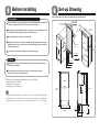
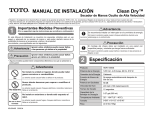
Before Installing
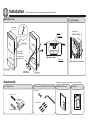
Some models may have different components as illustrated below.
Confirm the rough-in, major dimensions and wiring diagram before installation
in order to properly install the hand dryer and electrical wiring.
3-9/16″ (90mm)
2-3/8″ (60mm)
2-3/8″ (60mm)
1-9/16″ (40mm)
5-1/8″
(130mm)
FINISHED
WALL
Mounting surface should be even and smooth.
Confirmation must be made that the wall has enough strength for hand dryer
installation and be sure to use all the mounting hardware provided to securely
install the hand dryer.
1-9/16″
(40mm)
Junction box
location
26-5/16″
(668mm)
It is necessary to install circuit breaker for the power supply.
2″ (50mm)
1-3/16″ (30mm)
2. Others
2-3/4″ (70mm)
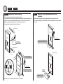
Pay special attention so that both the top cover and the sensor surface are
not flawed or scratched.
2-3/4″ (70mm)
9-15/16″ (252mm)
Recommended mounting bracket heights from floor are as follow:
*- Male/Female:
29-1/2” (750 mm)
28-3/4″
(730mm)
2″
(50mm)
Meets the American Disabilities Act Guidelines, ANSI A117.1 and CSA B651 requirements
when mounted in a recessed wall where the front surface is not more than 4” (102mm) from
finished wall and max. height of air blower outlet from finished floor is 47-1/4” (1200mm).
12-5/8″
(320mm)
1-9/16″
(40mm)
5-1/8″
(130mm)
6-7/16″
(164mm)
26-5/16″ (668mm)
3-1/8″ (80mm)
Do not place other devices using inverter or infrared sensor near the
hand dryer, this may cause malfunction.
- Children: 23-1/2” (598 mm)
- Handicapped: 21-1/2” (547 mm)
11-13/16″
(300mm)
1-5/16″
(34mm)
All electrical wiring should be installed in accordance with national/local codes
and regulations with assistance from a certified electrician.
27-9/16″ - 27-5/8″ (700±2 mm)
1. Precautions
OPEN WALL
*
FLOOR