1
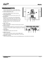
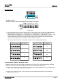
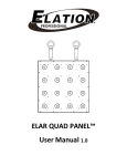
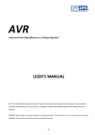
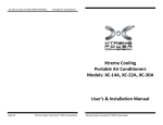
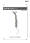
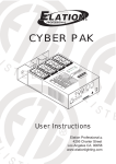
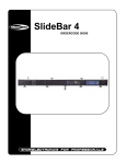
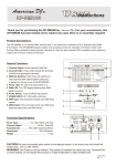
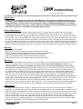
Instructions
No. 24-004-1516 Rev 1.1
Introduction:
Thank you for purchasing the DP-415 hybrid DMX pack. This product has been thoroughly tested
at our factory for quality and assurance. Your comments regarding our products and services are
always welcome. You can reach us by sending an e-mail to [email protected]. It is both a
privilege and pleasure serving you. Please be sure to read these instructions before operating this
unit and keep them in a safe place for possible reference later.
Product Description:
The DP-415 is a 4 channel portable dimmer/switch pack. Each output channel contains dual 15 Amp Edison
sockets that allow for two devices to be plugged into a single channel. Each channel can then be controlled via
standard DMX 512 signal by adjusting a relevant channel fader on your DMX console. The dip switches on the face
of the unit allow you to set the DMX patch address and operation mode for the pack. Standard binary code should
be used to set your DMX patch address. Dip Switch 10 is the “Mode” switch. The setting of this switch determines
the packs’ operation mode, either as a Dimmer or Switch pack. There are also 4 channel output LED’s that allow you
to view active channels. When the unit is set to Dim mode, these LED’s dim in real time as the relevant channel is
adjusted. A DMX signal indicator LED is also incorporated so that when DMX signal is present, the LED illuminates.
Warning:
This unit must be earthed.
Keep the unit dry, do not expose it to water or high levels of humidity.
Do not allow for any flammable liquids to come in close contact with the unit.
Technical repairs should be performed by an authorized technician.
Do not operate this unit if the internal components are exposed.
When replacing fuses, always replace with the same type and value.
Mounting:
The DP-415 was designed to be mounted on any form of pipe using an approved rigging clamp or onto any flat
surface via hardware that is not included with the product. Note: there should always be at least 12” of
clearance between the pack and anything surrounding it. It is also recommended that you use a safety
cable whenever mounting over head. To fasten a clamp to the unit, we recommend that you use either of the
two supplied center holes. One is on the top side and the other is on the rear. Use the one that better suites your
rig. Another means of hanging the unit, is by turning the rear panel around 180º. You will need a phillips head
screw driver to reverse the panel. Disconnect the units' power cord, remove the four phillips head screws on the
back of the unit, reverse the panel so the flanged side is facing out and replace the four phillips head screws.
This will allow you to hang the pack onto any 2” pipe (If you use this method to hang the unit, you must use a
safety cable to ensure the unit does not fall down). The final means of mounting this unit is onto a flat surface
where you can secure at least two bolts. This means an exposed wood beam, metal beam, wall that you can
determine has enough support to hold the units weight, etc... There are three holes on the back panel supplied for
this form of mounting. Use at least two of them, (preferably, the two outside holes) with at least 2” lag bolts.
Connections:
The DP-415 is supplied with a 15 Amp, 12 gauge power line cord. Plug the line cord into a service capable of
suppling up to 15 amps to the pack. Lamp loads should be plugged into the dual 15 Amp Edison sockets which are
fitted on the sides of the pack and are clearly marked on the front panel. Each channel can accept a load of up to 5
Amps or 600 Watts. Be sure to not overload any channel as this may result in blown fuses and malfunction. Using a
3 pin XLR, DMX cable, connect out of your DMX console or previous fixture in line and into the DMX IN of the
DP-415. Connect out of the DP-415, DMX OUT, and into the input of the next device in line. Set Dip Switches as
required (See Page 3- “Set DMX Address”). It is recommended that the last pack or fixture in line include a DMX
terminator into the Output. This will minimize data transmission errors.
Page 1
1
Front & Rear Panel Overview:
1. Dual Edison Sockets:
These are dual 120V Edison sockets. Each set of
sockets is labeled with the relevant channel number.
2. Channel Output LED’s (1-4):
These LED’s indicate relevant channel activity.
3. Power indicator LED:
This LED illuminates when the power switch is ON.
4. Dip-switches:
Dip switches 1-9 are used to set the starting DMX
address channel and dip switch 10 is used to select
the packs operation mode. When dip switch 10 is set
to “ON”, the pack functions as a Switch pack. When
dip switch 10 is set to “OFF”, the pack functions as
a Dimmer pack.
2
3
4
5
5. DMX indicator LED:
When this LED flashes it indicates that DMX signal is present.
6. Power Line Cord:
This cord should be plugged into a 120V~60Hz AC socket. Be
sure that the plug service is capable of supplying up to 15Amps
to the pack.
7. Power Switch:
This switches the packs power ON & OFF.
8. DMX IN Connector:
6
7
8
9
This 3 pin male XLR input connector receives DMX signal
from a DMX controller or previous DMX fixture in the data link.
9. DMX OUT Connector:
This 3 pin female XLR output connector sends DMX signal to the next fixture in the data link.
Page 2
Dip Switches:
on off
1. Set DMX Address:
Using binary values, set the required DMX patch address for your pack:
Switch# (1) (2) (3) (4) (5) (6) (7) (8) (9)
on
off
Value
1
2
4
8
16
32
64 128 256
(Binary)
DMX Address
As the illustration above shows, dip switches 1-9 should be used to set the packs DMX address.
Each dip switch incorporates a value that should be used when trying to figure out DMX
address settings. Dip Switch 1 = 1, Dip Switch 2 = 2, Dip Switch 3 = 4, Dip Switch 5 = 8, etc... The
value for every dip switch doubles counting from left to right. The goal is to try to get to the
required DMX patch number by using the least number of dip switches and adding the binary
values for each dip switch to land on the required address number.
For Example: These would be the dip switch settings for the specified DMX addresses.
Dip Switches Settings
DMX Address
(1) (2) (3) (4) (5) (6) (7) (8) (9)
Dip Switch Settings
(1) (2) (3) (4) (5) (6)
(7) (8) (9)
1
1
2
4
8
16
32
64 128
256
15
1
(1) (2) (3) (4) (5) (6) (7) (8) (9)
2
4
8
16
32
(1) (2) (3) (4) (5) (6)
64
128 256
(7) (8) (9)
2
1
2
4
8
16
32
64 128
256
106
1
(1) (2) (3) (4) (5) (6) (7) (8) (9)
2
4
8
16
32
(1) (2) (3) (4) (5) (6)
64
128 256
(7) (8) (9)
3
1
2
4
8
16
32
64 128
256
259
1
(1) (2) (3) (4) (5) (6) (7) (8) (9)
2
4
8
16
32
(1) (2) (3) (4) (5) (6)
64
128 256
(7) (8)
(9)
417
10
1
2
4
8
16
32
64 128
256
DMX Address
1
2
4
8
16
32
64
128
256
2. Select between "Dimmer" & "Switch" modes:
Setting dip switch 10 to the “ON” position, sets the DP-415 to act as a four channel switch pack. When dip
switch 10 is set to the "OFF" position, the DP-415 acts as a four channel dimmer pack.
When set to "Switch" mode, the channel output will switch ON at DMX value 128. Any DMX value
below 128 will switch the relevant channel OFF.
When set to "Dimmer" mode, channel output can be gradually dimmed UP or Down between
DMX values 000 to 255.
Page 3
Troubleshooting:
No Power to the pack:
Disconnect the power line cord. Reconnect the line cord to ensure proper connection. If the problem still
persists, check the building service panel and make sure the service circuit breakers are ON.
No Channel Output:
Disconnect the power line cord. Check the corresponding channel fuse or fuses by removing the four
phillips head screws on the rear panel to expose the circuit board and fuses. Each channel fuse is
marked on the PCB- TH1 = Channel 1, TH2 = Channel 2, TH3 = Channel 3 and Th4 = Channel 4. Check
the relevant channel fuse or fuses and replace if required. Always replace with same type and value. The
DP-415 incorporates four 6.3A 250V normal blow fuses. Replace rear panel and phillips head screws.
No DMX Control:
Check your dip switch settings. Ensure that the correct dip switches are set to the ON position. Check
the DMX channel patch on your DMX console if available.
If you’ve tried the above and the unit continues to malfunction, please contact ELATION® customer support
at (800) 322-6337, your unit may require service. Once you describe your problem to the customer service
representative, he or she will determine whether it should be sent in or not. If it does need to be sent in, you
will be issued a return authorization number that must accompany the package when sent in. Please write
this RA# on the outside of the box with a black marker and also write it on any packing slip that may be
included with the package.
Technical Specifications:
Power Input ............................................................................................................AC 120V~60Hz, 15A max.
Channel Output ..............................................................................................Total 15A max., 5A per channel
Fuse(Internal) ................................................................................................... F6.3A 250V 5x20mm(x4PCS)
DMX Input ................................................................................................................3-pin male XLR connector
DMX Output.........................................................................................................3-pin female XLR connector
Dimensions ............................................................................................................................ 180x177x64mm
Weight ................................................................................................................................................... 1.2 Kg
Notice Information
Specifications and improvements in the design of this product and this manual are
subject to change without any prior notice.
Page 4